This site uses cookies. By continuing to browse the ConceptDraw site you are agreeing to our Use of Site Cookies.
This vector stencils library contains 54 BDD symbols.
Use it to design your block definition diagrams using ConceptDraw PRO diagramming and vector drawing software.
"Block Definition Diagram
A block definition diagram is based on the UML class diagram, with restrictions and extensions as defined by SysML. ...
Block and ValueType Definitions
A SysML Block defines a collection of features to describe a system or other element of interest. A SysML ValueType
defines values that may be used within a model. SysML blocks are based on UML classes, as extended by UML composite structures. SysML value types are based on UML data types. Diagram extensions for SysML blocks and value types are described by other subheadings of this sub clause." [www.omg.org/ spec/ SysML/ 1.3/ PDF]
The vector stencils library "Block definition diagram" is included in the SysML solution from the Software Development area of ConceptDraw Solution Park.
Block definition diagram
Block definition diagram, object node, control operator frame, block definition diagram,
Block
Block, block,
Actor
Actor, actor,
Actor 2
Actor 2, actor,
Value type
Value type, value type,
Enumeration
Enumeration, enumeration,
Abstract definition
Abstract definition, abstract definition,
Abstract definition 2
Abstract definition 2, abstract definition,
Abstract definition 3
Abstract definition 3, abstract definition,
Stereotype property compartment
Stereotype property compartment, stereotype property compartment,
Namespace compartment
Namespace compartment, object node, namespace compartment,
Structure compartment
Structure compartment, structure compartment, object node,
Unit
Unit, unit,
Unit 2
Unit 2, unit,
Quantity kind
Quantity kind, quantity kind,
Instance specification
Instance specification, object node, instance specification,
Instance specification 2
Instance specification 2, instance specification,
Instance specification 3
Instance specification 3, instance specification,
Instance specification 4
Instance specification 4, structure compartment, instance specification,
Dependency
Dependency, dependency,
Reference association
Reference association, reference association,
Reference association 2
Reference association 2, reference association,
Part association
Part association, part association,
Part association 2
Part association 2, part association,
Shared association
Shared association, shared association,
Shared association 2
Shared association 2, shared association,
Multibranch part association
Multibranch part association, multibranch part association,
Multibranch shared association
Multibranch shared association, multibranch shared association,
Generalization
Generalization, generalization,
Multibranch generalization
Multibranch generalization, multibranch generalization,
Generalization set, disjoint
Generalization set, disjoint, disjoint generalization set,
Generalization set, overlapping
Generalization set, overlapping, overlapping generalization set,
Block namespace containment
Block namespace containment, block namespace containment,
Participant property
Participant property, reference association, participant property, object node, connector property,
Participant property 2
Participant property 2, structure compartment, reference association, participant property, object node, actor,
Participant property 3
Participant property 3, reference association, participant property, object node,
Connector property
Connector property, object node, connector property,
Conjugated ports
Conjugated ports, port, object node, conjugated port,
Conjugated ports 2
Conjugated ports 2, port, object node, conjugated port,
Ports with flow properties
Ports with flow properties, port, object node,
Port (compartment notation)
Port (compartment notation), port,
Port (nested)
Port (nested), port, object node, nested port,
Proxy port
Proxy port, proxy port, port, object node,
Full port
Full port, port, object node, full port,
Flow property
Flow property, flow property,
Required and provided features
Required and provided features, required and provided features,
Interface block
Interface block, interface block, interface,
Item flow
Item flow, port, object node, item flow,
Item flow 2
Item flow 2, port, object node, item flow, item property,
Item flow 3
Item flow 3, port, object node, item flow, connector property,
Interface
Interface, interface,
Required and provided interfaces
Required and provided interfaces, required interface, required and provided interfaces, port, object node, interface,
Required and provided interfaces 2
Required and provided interfaces 2, required interface, required and provided interfaces, port, object node, interface,
Constraint block
Constraint block, constraint block,
The vector stencils library "Block definition diagram" contains 54 SysML symbols.
Use it to design your block definition diagrams using ConceptDraw PRO diagramming and vector drawing software.
"Block Definition Diagram
A block definition diagram is based on the UML class diagram, with restrictions and extensions as defined by SysML. ...
Block and ValueType Definitions
A SysML Block defines a collection of features to describe a system or other element of interest. A SysML ValueType
defines values that may be used within a model. SysML blocks are based on UML classes, as extended by UML composite structures. SysML value types are based on UML data types. Diagram extensions for SysML blocks and value types are described by other subheadings of this sub clause." [www.omg.org/ spec/ SysML/ 1.3/ PDF]
The SysML shapes example "Design elements - Block definition diagram" is included in the SysML solution from the Software Development area of ConceptDraw Solution Park.
SysML block definition diagram symbols
SysML block definition diagram symbols, value type, unit, structure compartment, stereotype property compartment, shared association, required interface, required and provided interfaces, required and provided features, reference association, quantity kind, proxy port, port, participant property, part association, overlapping generalization set, object node, nested port, namespace compartment, multibranch shared association, multibranch part association, multibranch generalization, item flow, item property, item flow, interface block, interface, interface, instance specification, generalization, full port, flow property, enumeration, disjoint generalization set, dependency, control operator frame, constraint block, connector property, conjugated port, block namespace containment, block definition diagram, block, actor, abstract definition,

ConceptDraw DIAGRAM Compatibility with MS Visio

The powerful diagramming and business graphics tools are now not exception, but the norm for today’s business, which develop in incredibly quick temp. But with the abundance of powerful business diagramming applications it is important to provide their compatibility for effective exchange the information between the colleagues and other people who maybe use different software in their work. During many years Microsoft Visio™ was standard file format for the business and now many people need the visual communication software tools that can read the Visio format files and also export to Visio format. The powerful diagramming and vector drawing software ConceptDraw DIAGRAM is ideal from the point of view of compatibility with MS Visio. Any ConceptDraw DIAGRAM user who have the colleagues that use MS Visio or any who migrates from Visio to ConceptDraw DIAGRAM , will not have any problems. The VSDX (Visio′s open XML file format) and VDX formatted files can be easily imported and exported by ConceptDraw DIAGRAM , you can see video about this possibility.

Mechanical Engineering

ConceptDraw DIAGRAM is the best diagramming and vector drawing software. Now, enhanced with Mechanical Engineering solution from the Engineering area of ConceptDraw Solution Park it became ideal for creating: Technical Mechanical Drawings, Mechanical Engineering Diagrams, Pneumatic Schematics, Hydraulic Schemes, etc.

Building Drawing. Design Element: Piping Plan

When you are going to build a house or to make repairs of new built home, apartment, office, shop, or to renovate any other premises, in many cases you will need to make the package of drawings, plans and documents, including the such important plans as the Overall floor plan, Interior design plan, Ceiling plan, Electrical system plan, and of course the Plumbing plan, Water supply system plan, and Piping Plan. When choosing between the modern software for building construction, planning and design, we recommend you to select the multifunctional building plan software ConceptDraw DIAGRAM enhanced with Plumbing and Piping Plans solution from the Building Plans area of ConceptDraw Solution Park. This solution provides large variety of examples, samples, quick-start templates and libraries of pipes, plumbing and valves vector design elements for design and construction the Plumbing and Piping Plans, schematics and annotated diagrams for hot and cold water supply systems, water lines and waste water disposal systems.

Create Floor Plans Easily
with ConceptDraw DIAGRAM Floor Design Software

How to create Floor Plan Design easy and effectively? You can invite an interior designer and trust this work to him, which is usually expensive and result may not always meet your expectations. Another way is to design it yourself, but at this case you need to have special skills, knowledges and abilities, among them basic knowledge of the composition rules, color theory, materials science and software for interior design development. The ability to use specialized software for drawing is especially valuable, useful and saves your time. ConceptDraw DIAGRAM is one of the best among similar software, it offers extensive functionality, powerful tools, a lot of features, and is simple for using, so can be applied by everyone without efforts. Enhanced with Floor Plans and other solutions from the Building Plans area, the ConceptDraw DIAGRAM software helps easily create unique and harmonious interior designs, and draw in desired scale professional-looking Floor Plans and Layouts for homes, apartments, hotels, offices, and other buildings. ConceptDraw DIAGRAM is a full Visio compatibility and better alternative for students, teachers and business professionals to reliably create kinds of flowcharts, organizational charts, network diagrams, floor plans, electrical diagrams, software design diagrams, maps and more.
How to Draw a Floor Plan

Concept Maps

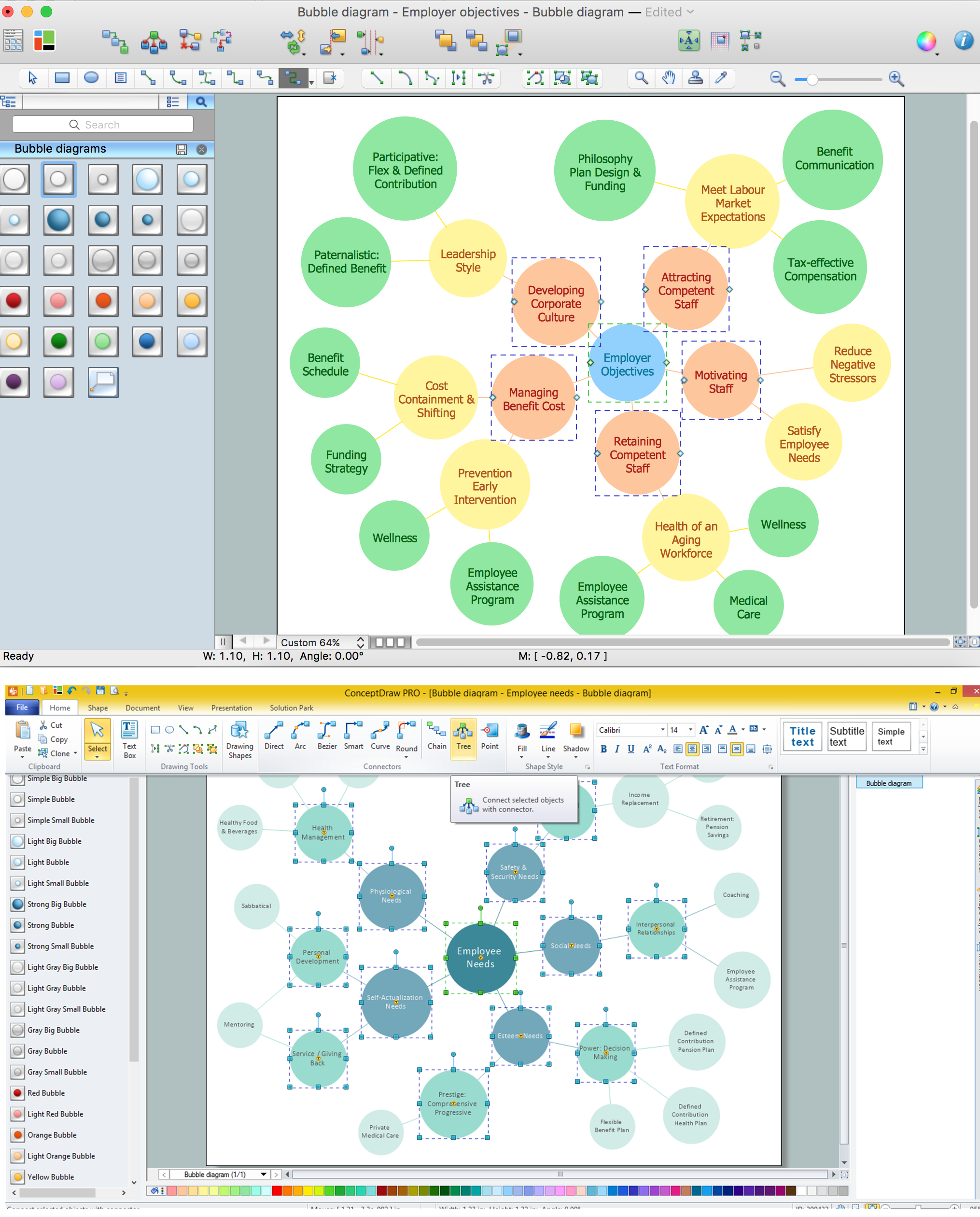
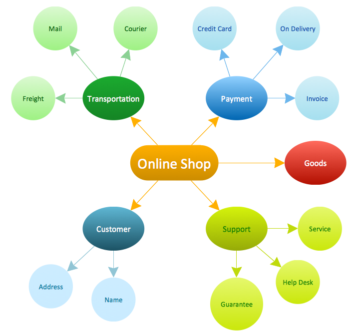
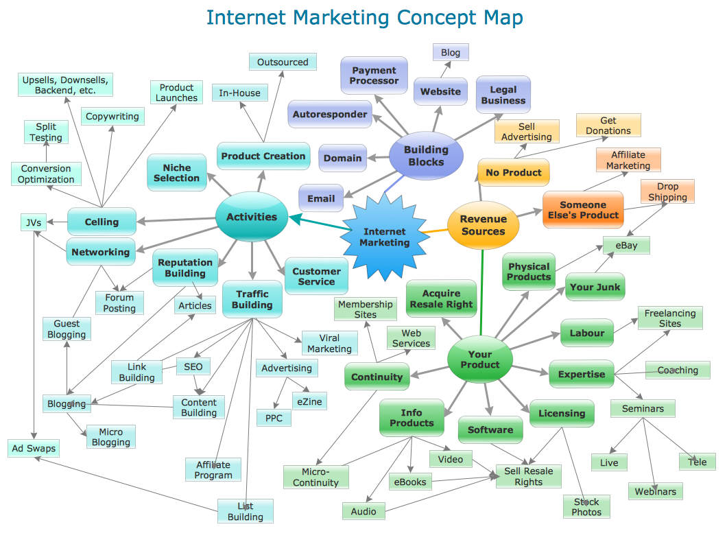
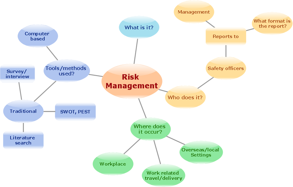
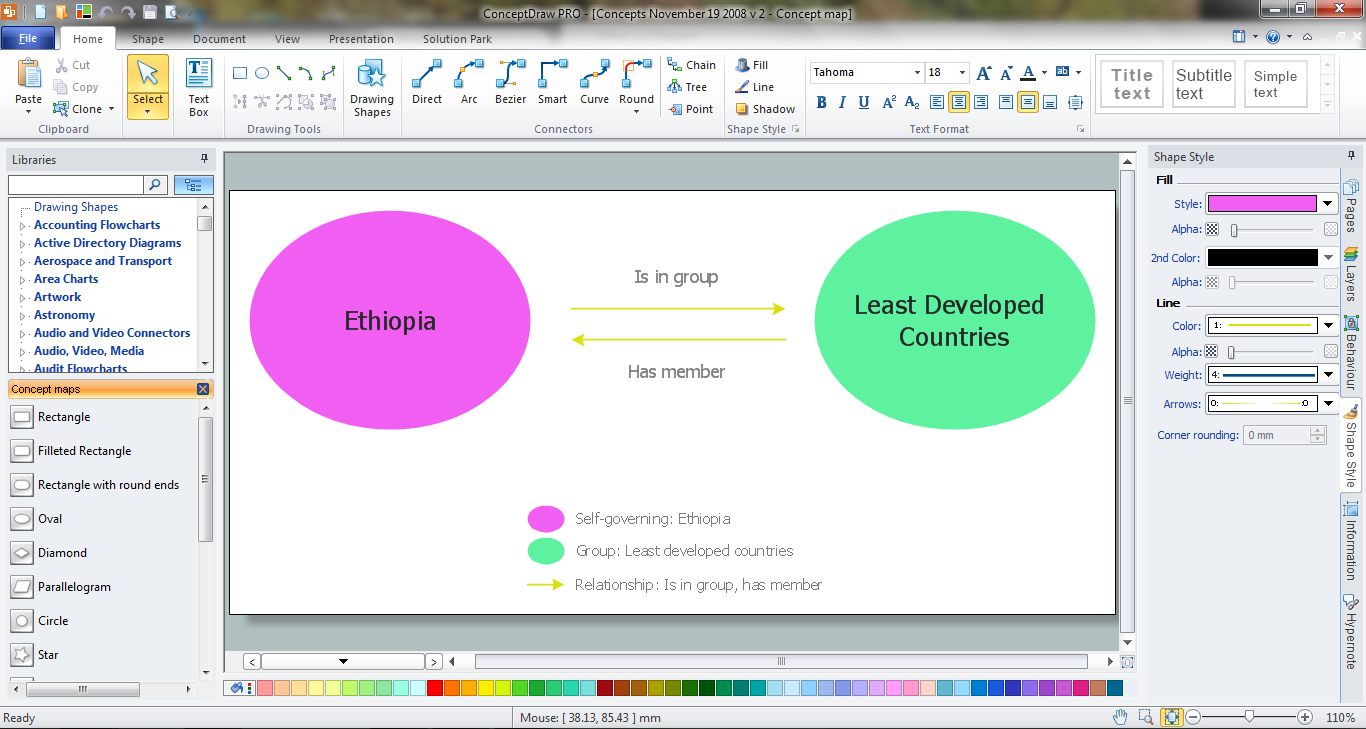
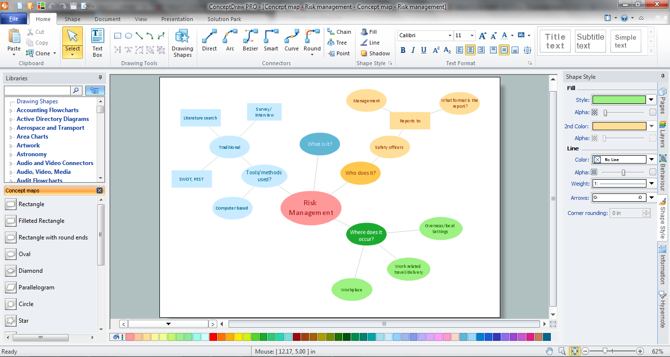
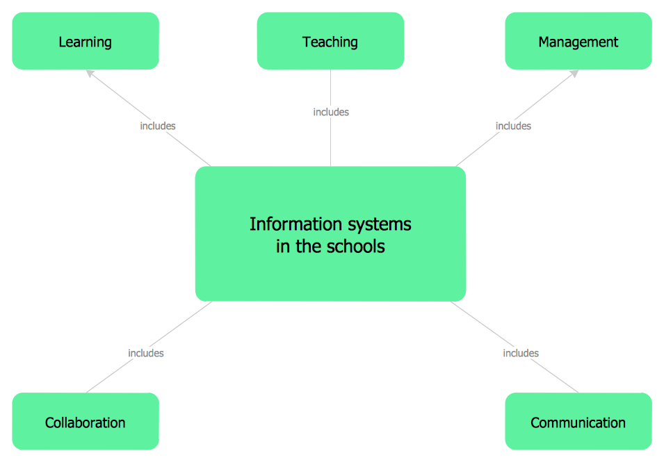
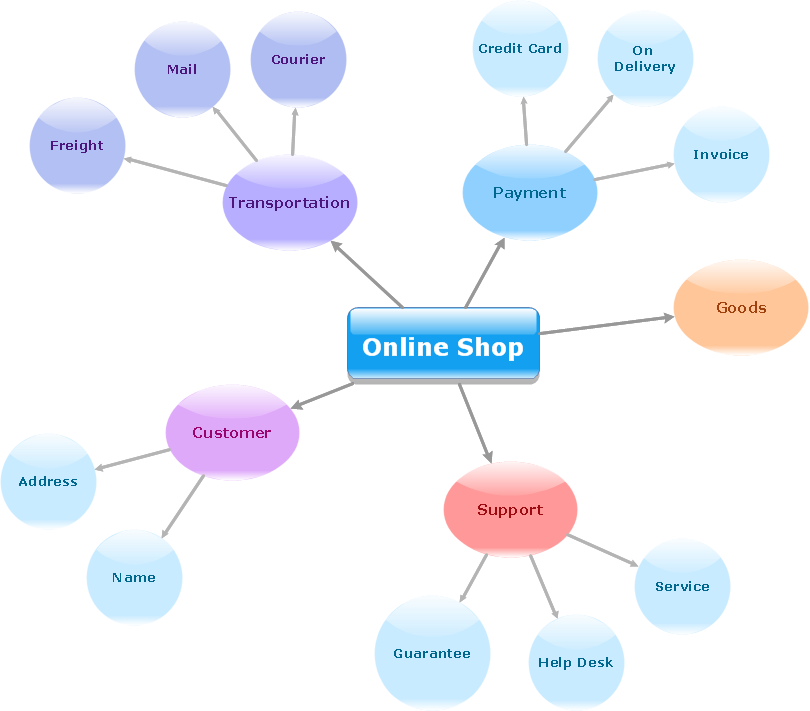
As concept map consists from conception-blocks and links between them, you can use ConceptDraw library objects and add to a document as much objects as you need. ConceptDraw tools let you to edit, group, move objects, change their appearance and add text signs and raster or vector pictures. ConceptDraw DIAGRAM diagramming and vector drawing software extended with Concept Maps Solution from the "Diagrams" Area is effective tool for creating professional looking Concept Maps.
This example was drawn on the base of figure 1 on the webpage "Template: OASIS:FunctionalBreakdownStructure" from the OASIS website.
"The FunctionalBreakdownStructure template describes how to represent a relationship between a FunctionalElementDefinition and another FunctionalElementDefinition that is a constituent.
The SysML Block Definition diagram in Figure 1 shows how a functional breakdown is represented in the PLCS PSM."
[docs.oasis-open.org/ plcs/ plcslib/ v1.0/ csprd01/ data/ contexts/ OASIS/ templates/ FunctionalBreakdownStructure/ template.html]
"A block definition diagram is based on the UML class diagram, with restrictions and extensions as defined by SysML." [omg.org/ spec/ SysML/ 1.3/ PDF]
The example "SysML block definition diagram - Function Breakdown model" was drawn using the ConceptDraw PRO diagramming and vector drawing software extended with the SysML solution from the Software Development area of ConceptDraw Solution Park.
Example of SysML BDD
Example of SysML BDD, unit, part association, generalization, control operator frame, block definition diagram, block,

Picture Graph

A Picture Graph is a popular and widely used type of a bar graph, which represents data in various categories using the pictures. ConceptDraw DIAGRAM extended with Picture Graphs solution from the Graphs and Charts area of ConceptDraw Solution Park is the best software for fast and simple drawing professional looking Picture Graphs.

Swim Lane Diagrams

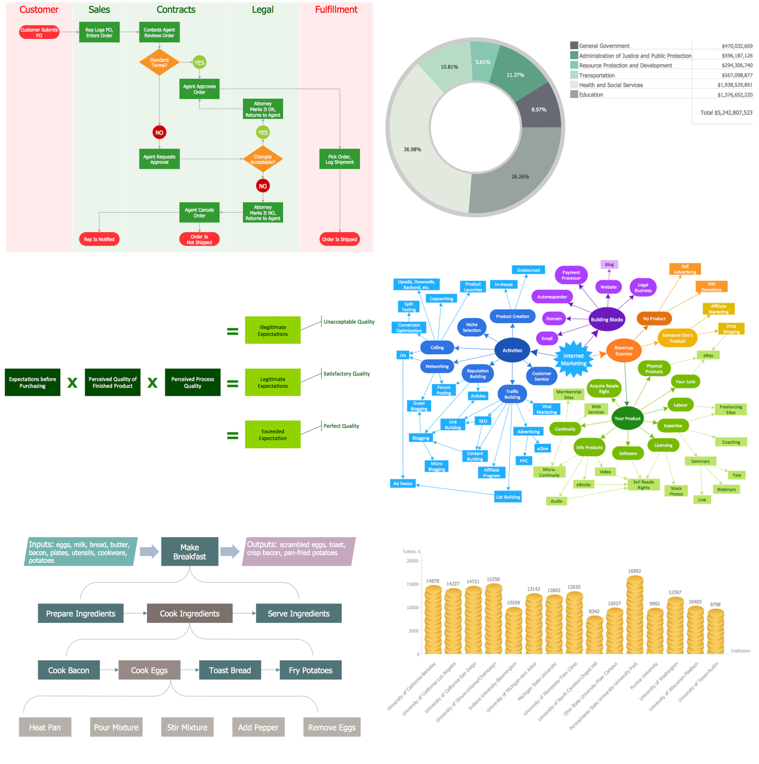
Swim Lane Diagrams are the kind of process flow diagrams and effective tool for documenting the business processes required for any business company for its productive work, for easy defining the weak points, reasons of defects, or delays during the process. Swim Lane Diagram is based on the IDEF3 standard and was developed primarily for using in projecting. Its name derives from the use of horizontal or vertical lanes. The blocks that denote the parts of the processes are arranged within definite lanes according to the belonging to responsible worker. So the process of any complexity is visually divided into the parts and represented with indication the responsibility for execution of each part. This significantly facilitates the comprehension of its work. Use the ConceptDraw DIAGRAM software and predesigned vector objects from the Swim Lanes library of Business Process Mapping Solution included to ConceptDraw Solution Park to easy develop Swim Lanes Flowcharts and Diagrams, for modeling and documenting the business processes in a simple and visual graphic form.

Produce Professional Diagrams More Quickly, Easily and Cost Effectively

ConceptDraw Arrows10 Technology - This is more than enough versatility to produce professional diagrams more quickly. Professional diagramming software for mac helps you create variety diagrams, graphics, charts, live dashboards and plenty of graphics and pictures for your business and study.

How To Make a Concept Map

How to make a Concept Map fast and easy? ConceptDraw DIAGRAM diagramming and vector drawing software extended with Concept Maps Solution from the "Diagrams" Area is the best choice for those who want design professional looking Concept Map in minutes.
The vector stencils library "Concept maps" contains 16 geometrical shapes.
Use it to create your concept maps, mindmaps, idea maps, tree diagrams, omega maps, cluster diagrams and spider diagrams.
The symbols example "Concept maps - Vector stencils library" was created using the ConceptDraw PRO diagramming and vector drawing software extended with the Concept Maps solution from the area "What is a Diagram" of ConceptDraw Solution Park.
Rectangle
Rectangle, concept map,
Rounded rectangle
Rounded rectangle, concept map,
Stadium
Stadium, concept map,
Oval
Oval, concept map,
Diamond
Diamond, concept map,
Parallelogram
Parallelogram, concept map,
Circle
Circle, concept map,
Star
Star, concept map,
Hexagon
Hexagon, concept map,
Cloud
Cloud, concept map,
Starburst
Starburst, concept map,
Arrow
Arrow, concept map,
Envelope
Envelope, concept map,
Note
Note, concept map,
Callout
Callout, concept map,
Table
Table, concept map,

Building Drawing Software for Design Site Plan

Site plan is a detailed architectural plan or document, landscape architecture project for considered object. It is a part of technical design documentation that illustrates the arrangement of buildings, trails, roads, parking, lighting, water lines, sanitary sewer lines, drainage facilities, landscape and garden elements. Site plans are constructed by architects, landscape designers or licensed design engineers, and used by the builders, contractors and installers when constructing or making improvements to some property. They reflect the main design ideas and give an instantly vision of future result after the plan's implementation. They have special value for the large projects of single or multi-floor buildings, and for accomplishment the whole districts. ConceptDraw DIAGRAM extended with Site Plans solution offers the powerful building drawing software tools and vector design elements for development and drawing Site plans and Landscape design drawings, Residential and Commercial landscape designs, Parks and Landscaping territories plans, Yard layouts, etc.

Comparing ConceptDraw DIAGRAM to Omnigraffle

Comparing ConceptDraw DIAGRAM to Omnigraffle you can see a lot of benefits of ConceptDraw products. First, the main, ConceptDraw applications are cross-platform and available in two independent and concurrent versions for Macintosh (macOS) and PC (Windows). ConceptDraw gives you the per named license, that you can use simultaneously for your both Macintosh and PC, at work and at home. Free access to the ConceptDraw Solution Park offers you the great number of solutions with hundreds of templates and samples, and thousands of ready-to-use vector objects for quick and easy creation diagrams, drawings, illustrations and Mind Maps. Besides, thanks to Ingyre Technology is provided the integration with Microsoft Office applications and capabilities of limitless exchange the information. The ConceptDraw Live Objects technology lets you design the visual dynamically-updated dashboards, the Rapid Draw technology allows creating the diagrams in minutes. The extensive presentation capabilities help you create lush and beautiful presentation slideshows from your ConceptDraw documents.

ConceptDraw DIAGRAM Comparison with Omnigraffle Professional and MS Visio

ConceptDraw DIAGRAM comparison with Omnigraffle Professional and MS Visio shows you the significant benefits of ConceptDraw DIAGRAM , which offers varied useful drawing tools, the capability of creation multi-page documents, wide export / import capabilities in graphics formats, integration with Visio and Microsoft Office applications, availability of built-in scripting language and ConceptDraw Solution Park with numerous solutions, vector objects libraries, templates and samples. Business today is conducted with incredible rate and dynamic presentations become very popular. Sometimes while conducting the business, may happen that you can't describe some situation, state, or process with only words. In these cases, it is convenient to include graphics and diagrams associated with the text. This guarantees successful communication with other stakeholders and team members, and faultless understanding the information by them. The combination of words and graphics is an ideal combination, it improves the clarity and removes any doubt. ConceptDraw DIAGRAM helps you easily create any kinds of diagrams and dynamic presentations too.

ConceptDraw DIAGRAM The best Business Drawing Software

ConceptDraw DIAGRAM is new software for business and technical drawing. Powerful business drawing tools, extensive libraries with pre-drawn shapes, free samples of business drawings, technical drawings and flowcharts, support of many graphic formats enable users to visually develop their business drawings charts and diagrams in any combination of drawings, diagrams and flow charts.

Matrices

ConceptDraw DIAGRAM extended with Matrices Solution from the Marketing Area of ConceptDraw Solution Park is a powerful software for drawing various types of Marketing Matrices: Ansoff Matrix, BCG Matrix, Deployment Chart, Feature Comparison Chart, Competitive Strategies Matrix, Flow Process Chart, Porter's Value Chain Diagram, Positioning Map, and many others.

Use Case Diagrams technology with ConceptDraw DIAGRAM

Use case diagrams are used at the development of software and systems for definition of functional system requirements or system of systems. Use case diagram presents the consecution of object’s actions (user’s or system’s) which are executed for reaching the definite result.