How To use Appliances Symbols for Building Plan
One of the obligatory documents that is included to design project of home, appartment, office center, or any other premise is the plan of arrangement of different appliances and home appliances. Creation the plan of such kind lets you to preplan the location of appliances, to make sure in convenience of their location and to envisage all nuances. Well thought-out plan helps to avoid mistakes and future reworks, especially in relation to the location of major and large appliances. ConceptDraw DIAGRAM software extended with Floor Plans solution offers the perfect set of drawing tools, samples, examples, templates and ready-to-use vector objects that let you easily develop best layouts for your rooms, kitchen, bathroom, laundry, etc. Ready-made symbols of appliances included to the Appliances library are ideal and even indispensible for designing professional building plans and appliances layouts for homes, commercial and office premises. When designing your plans, you can make several variants and choose the best solution.Electrical Symbols — Thermo
A thermocouple is an electrical device consisting of two different conductors forming electrical junctions at differing temperatures. A thermocouple produces a temperature-dependent voltage as a result of the thermoelectric effect, and this voltage can be interpreted to measure temperature. Thermocouples are a widely used type of temperature sensor. 26 libraries of the Electrical Engineering Solution of ConceptDraw DIAGRAM make your electrical diagramming simple, efficient, and effective. You can simply and quickly drop the ready-to-use objects from libraries into your document to create the electrical diagram.Single-line Diagram
Single-line diagram (SLD) also known as a One-line diagram is a simplest symbolic representation of a portion or entire electric power system. It is helpful for both the development and maintenance of electrical system, troubleshooting, rerouting power after faults, and changing system configurations in order to increase its performance, reliability, and safety. ConceptDraw's One-line Diagrams solution offers powerful tools to create Single-line diagrams of any complexity, reflect the facility’s electrical distribution system and show how incoming power is distributed to equipment in an electrical circuit. Study and evaluate effectively the short-circuit, arc flash, and electrical safety; develop, install and maintain the electrical system.
 Electric and Telecom Plans
Electric and Telecom Plan solution was developed by the CS Odessa team to provide ConceptDraw DIAGRAM users with stencils related to electricity and telecommunications, electrical floor plan symbols and ready-made examples. The solution tools are useful for creating the electric visual plans and telecom drawings, home electrical plan, residential electric plan, telecom wireless plan, electrical floor plans whether as a part of the building plans or the independent ones. This solution is useful for electricians, architects, interior designers, telecommunications managers, builders, technicians, and more construction-related specialists.
What Is a Concept Map
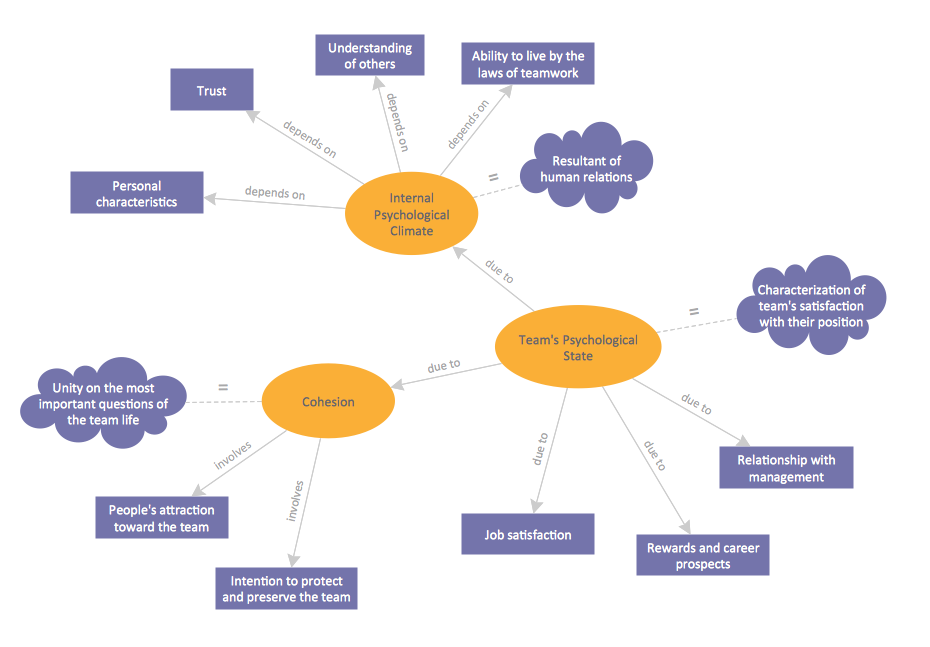
What is a Concept Map and what software is effective for its design? A concept map or conceptual diagram is a diagram that depicts suggested relationships between concepts. As for effective software - we suggest you to pay attention for the ConceptDraw DIAGRAM diagramming and vector drawing software. Extended with Concept Maps Solution from the "Diagrams" Area it is a real godsend for you.Electrical Symbols — Switches and Relays
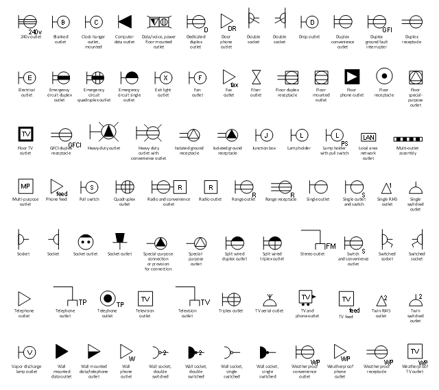
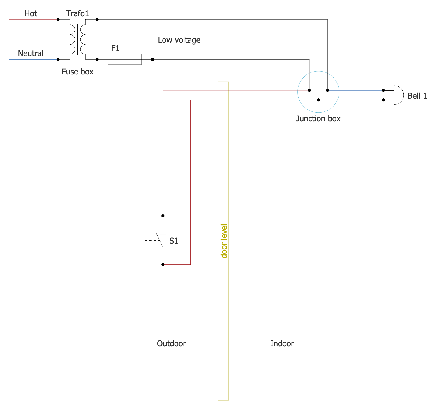
In electrical engineering, a switch is an electrical component that can break an electrical circuit, interrupting the current or diverting it from one conductor to another. The mechanism of a switch may be operated directly by a human operator to control a circuit (for example, a light switch or a keyboard button), may be operated by a moving object such as a door-operated switch, or may be operated by some sensing element for pressure, temperature or flow. A relay is a switch that is operated by electricity. Switches are made to handle a wide range of voltages and currents; very large switches may be used to isolate high-voltage circuits in electrical substations. 26 libraries of the Electrical Engineering Solution of ConceptDraw DIAGRAM make your electrical diagramming simple, efficient, and effective. You can simply and quickly drop the ready-to-use objects from libraries into your document to create the electrical diagram.The vector stencils library "Outlets" contains 84 electrical outlet symbols.
Use it in ConceptDraw DIAGRAM software to draw your layouts of AC power plugs and sockets, building interior design, electrical and telecom floor plans, circuit schematics, cabling schemes, home wiring diagrams.
"AC power plugs and sockets are devices that allow electrically operated equipment to be connected to the primary alternating current (AC) power supply in a building. Electrical plugs and sockets differ in voltage and current rating, shape, size and type of connectors. The types used in each country are set by national standards, some of which are listed in the IEC technical report TR 60083, Plugs and socket-outlets for domestic and similar general use standardized in member countries of IEC.
Plugs and sockets for portable appliances started becoming available in the 1880s, to replace connections to light sockets with easier to use wall-mounted outlets. A proliferation of types developed to address the issues of convenience and protection from electric shock. Today there are approximately 20 types in common use around the world, and many obsolete socket types are still found in older buildings. Co-ordination of technical standards has allowed some types of plugs to be used over wide regions to facilitate trade in electrical appliances, and for the convenience of travellers and consumers of imported electrical goods. Some multi-standard sockets allow use of several different types of plugs; improvised or unapproved adapters between incompatible sockets and plugs may not provide the full safety and performance of an approved adapter." [AC power plugs and sockets. Wikipedia]
The AC power plugs and sockets symbol set example "Design elements - Outlets" is included in Electrical and Telecom Plans solution from Building Plans area of ConceptDraw Solution Park.
 Energy Industry Infographics
Energy Industry Infographics solution is ideal for designing energy-related business infographics, diagrams, charts, illustrations for documents and presentations. It provides a set of libraries with special vector energy industry symbols, icons for electrical power industry, nuclear power industry, fossil fuel industry, and renewable energy industry, energy icons of fuel gas, liquid fuel, solid fuel, industry icons of electrical substations, power plants. Collection of samples including nuclear fuel cycle and energy distribution schematics, electrical substation diagram, energy intelligence dashboard, electricity grid schematics, and many more is also included. This solution is indispensable for all engineers, chefs, managers, marketers, and other professionals working in energy industry.
Home Appliances
Home appliances also called domestic appliances, electric appliances, or household appliances are machines, instruments, or electrical devices, which assist in household functions like cleaning, washing, cooking, food preservation, heating, and many more. They easier daily home workload, are convenient for using, offer effective help, and provide labor-saving and time-saving capabilities. Home Automation and Wiring solution is effective and convenient to develop modern solutions for home automation and create plans of home appliances arrangement. Design several plans and then choose the best one to be realized at your home, apartment, or office.Concept Map
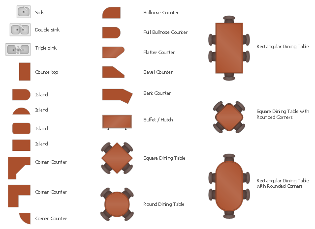
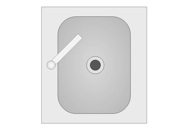
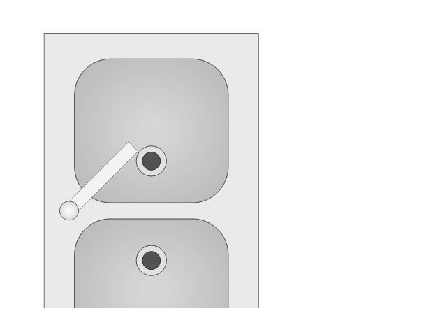
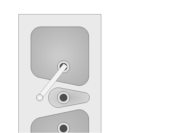
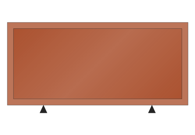
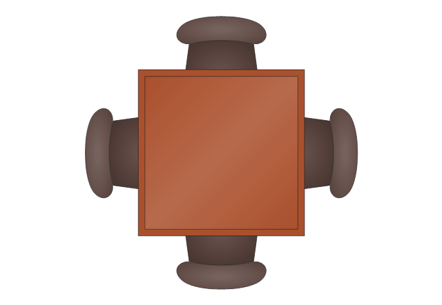
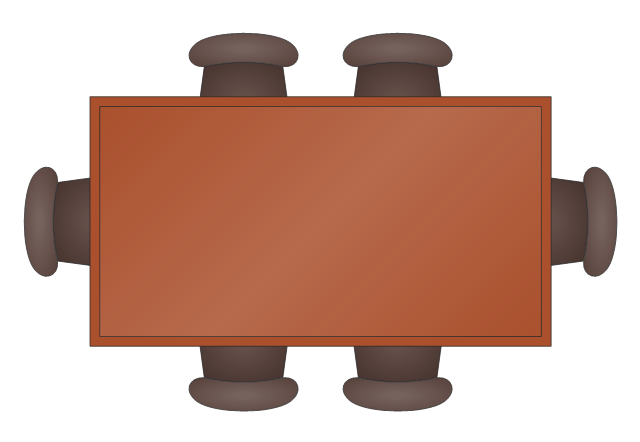
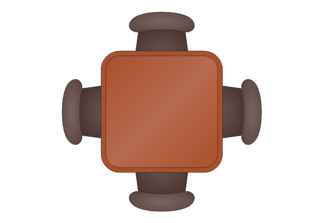
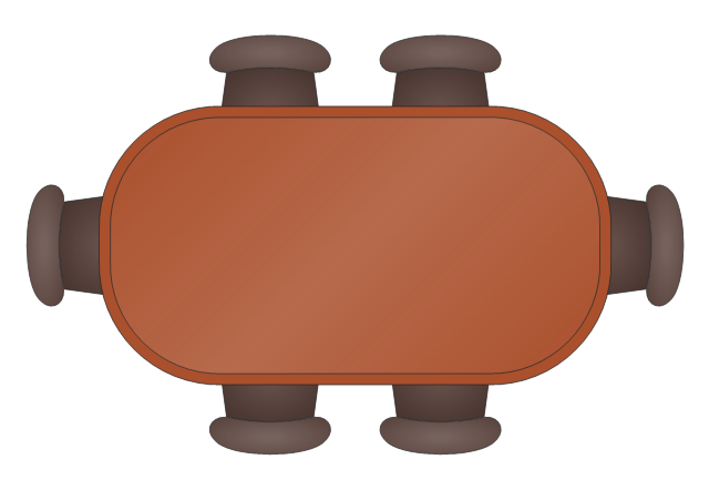
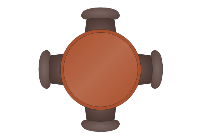
A concept map is a way of representing relationships between ideas, images, or words. How to draw a Concept Map quick, easy and effective? ConceptDraw DIAGRAM offers the unique Concept Maps Solution from the "Diagrams" Area that will help you!The design elements library Kitchen and dining room contains 22 symbols of furniture and applience.
Use the vector stencils library Kitchen and dining room to draw the furniture and applience layout floor plan of kitchen and dining room.
"A kitchen is a room or part of a room used for cooking and food preparation.In the West, a modern residential kitchen is typically equipped with a stove, a sink with hot and cold running water, a refrigerator and kitchen cabinets arranged according to a modular design. Many households have a microwave oven, a dishwasher and other electric appliances. The main function of a kitchen is cooking or preparing food but it may also be used for dining, food storage, entertaining, dishwashing and laundry." [Kitchen. Wikipedia]
"A dining room is a room for consuming food. In modern times it is usually adjacent to the kitchen for convenience in serving, although in medieval times it was often on an entirely different floor level. Historically the dining room is furnished with a rather large dining table and a number of dining chairs; the most common shape is generally rectangular with two armed end chairs and an even number of un-armed side chairs along the long sides." [Dining room. Wikipedia]
The shapes library Kitchen and dining room is provided by the Floor Plans solution from the Building Plans area of ConceptDraw Solution Park.
The vector stencils library "Kitchen and dining room" contains 22 shapes of furniture and equipment. Use it for drawing kitchen and dining room design plans, furniture and applience layouts in the ConceptDraw PRO diagramming and vector drawing software extended with the Floor Plans solution from the Building Plans area of ConceptDraw Solution Park.
- How To use Appliances Symbols for Building Plan | Electrical ...
- How To use Appliances Symbols for Building Plan | Home Electrical ...
- Electrical Symbols, Electrical Diagram Symbols | How To use House ...
- Visio Home Electrical Appliance Template
- Electrical Engineering | Appliances - Vector stencils library | Design ...
- How To use Appliances Symbols for Building Plan | Design ...
- Electrical Symbols, Electrical Diagram Symbols | Electrical Symbols ...
- How To use Appliances Symbols for Building Plan | Restaurant ...
- Design elements - Appliances | Electrical Symbol For Cooker
- Design elements - Outlets | Symbols Of Electrical Appliance


