HelpDesk
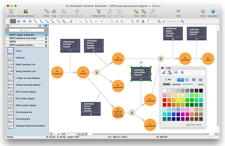
How to create an IDEF3 diagram using ConceptDraw PRO
IDEF3 is a member of the IDEF family of modeling methods that can be used to describe operations in a business process. An IDEF3 diagram provides a description of actual process flow within an organization or business, or the changes that occur to an object within that system. This method of knowledge capture is recorded in two different perspectives - users are able to create both process schematics and object schematics using the IDEF3 schematic symbols. ConceptDraw has created a solution that collects all symbols necessary to create professional IDEF3 diagrams. IDEF methodology is suitable for almost any form of business, and for anyone who needs to record enterprise architecture in a process driven manner. The IDEF Business Process Diagram solution and ConceptDraw PRO cater for these needs, giving both beginner and experienced users the tools they need to create effective business process diagrams.Basic Flowchart Symbols and Meaning
Flowcharts are the best for visually representation the business processes and the flow of a custom-order process through various departments within an organization. ConceptDraw PRO diagramming and vector drawing software extended with Flowcharts solution offers the full set of predesigned basic flowchart symbols which are gathered at two libraries: Flowchart and Flowcharts Rapid Draw. Among them are: process, terminator, decision, data, document, display, manual loop, and many other specific symbols. The meaning for each symbol offered by ConceptDraw gives the presentation about their proposed use in professional Flowcharts for business and technical processes, software algorithms, well-developed structures of web sites, Workflow diagrams, Process flow diagram and correlation in developing on-line instructional projects or business process system. Use of ready flow chart symbols in diagrams is incredibly useful - you need simply drag desired from the libraries to your document and arrange them in required order. There are a few serious alternatives to Visio for Mac, one of them is ConceptDraw PRO. It is one of the main contender with the most similar features and capabilities.
HelpDesk
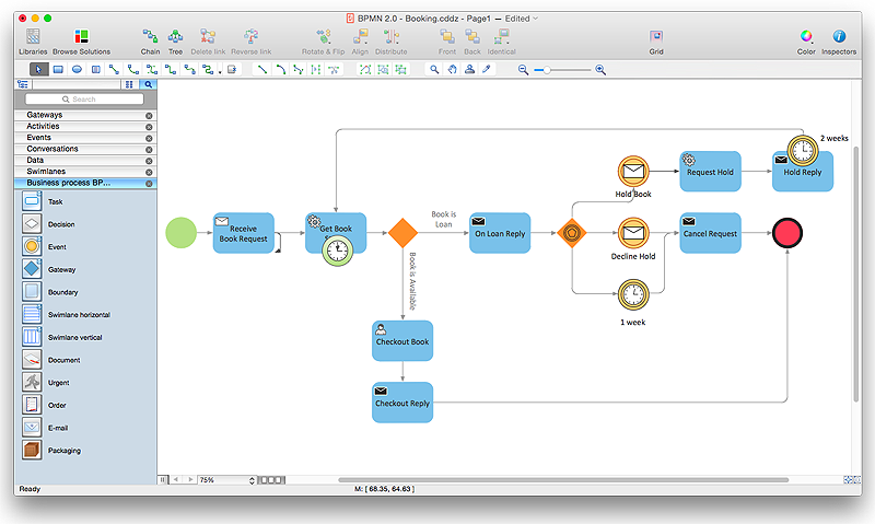
How to Create a BPMN Diagram Using ConceptDraw PRO
Business Process Modeling Notation (BPMN) is a method of illustrating business processes in the form of a diagram. The most effective method of creating or analyzing a business process is to visually interpret the steps using a business process diagram, flowchart or workflow. This is known as business process modeling, and will be performed within a company by a team who have detailed knowledge of company process, and analysts with expertise in the modeling discipline. The objective is often to increase production or lower costs — by modeling the process initially using a flowchart, inefficiencies and problems can be spotted before committing to a decision or strategy. You can create BPMN diagrams using the ConceptDraw PRO diagramming tools. ConceptDraw have designed a solution that combines BPMN v2.0 methodology and graphical notification into one powerful package. The Business Process Diagrams solution from ConceptDraw Solution Park provides a comprehensive collection of vectorGoal Line Formation (Offense/Defense) Diagram
ConceptDraw PRO software extended with the Football solution delivers libraries, templates and samples allowing football fans or specialists to draw football-related schemas in minutes. A complete set of predesigned fields and positions make drawing schemas as quickly as possible.
 Football
The Football Solution extends ConceptDraw PRO v9.5 (or later) software with samples, templates, and libraries of vector objects for drawing football (American) diagrams, plays schemas, and illustrations. It can be used to make professional looking documen
ERD Symbols and Meanings
Entity Relationship Diagram (ERD) is a popular software engineering tool for database modeling and illustration the logical structure of databases, which uses one of two notations - Chen's or Crow’s Foot. Crow's foot notation is effective when used in software engineering, information engineering, structured systems analysis and design. Each of these notations applies its own set of ERD symbols. Crow's foot diagrams use boxes to represent entities and lines between these boxes to show relationships. Varied shapes at the ends of lines depict the cardinality of a given relationship. Chen's ERD notation is more detailed way to represent entities and relationships. ConceptDraw PRO application enhanced with all-inclusive Entity-Relationship Diagram (ERD) solution allows design professional ER diagrams with Chen's or Crow’s Foot notation on your choice. It contains the full set of ready-to-use standardized ERD symbols and meanings helpful for quickly drawing, collection of predesigned ERD samples, examples and templates. ConceptDraw Pro is a great alternative to Visio for Mac users as it offers more features and can easily handle the most demanding professional needs.
- Arrow circle chart - Template | Pie Chart Examples and Templates ...
- Circular Arrows Diagrams
- Pie Chart Examples and Templates | Design elements ...
- Picture Graphs | How to Create a Picture Graph in ConceptDraw ...
- Basic Flowchart Symbols and Meaning | HR arrows - Vector stencils ...
- Goal Line Formation (Offense/Defense) Diagram | Offensive Play ...
- Basic Flowchart Symbols and Meaning | Flowchart | Flowchart ...
- Pneumatic 5-ported 3-position valve template - Mac | Design ...
- Offensive Play – Double Wing Wedge – Vector Graphic Diagram ...
- Picture Graphs | Graphs and Charts Area | Picture graph ...
- Diagram Of Activity Design
- Sales arrows - Vector stencils library | HR arrows - Vector stencils ...
- How to Draw a Pictorial Chart in ConceptDraw PRO | Sample ...
- Product life cycle graph | Product life cycle graph - Template ...
- Elements location of a welding symbol | Design elements ...
- Offensive Formation – T-Formation – Diagram | Defensive Formation ...
- Landmarks - Vector stencils library | ConceptDraw Solution Park ...
- Basic Flowchart Symbols | Process Flowchart | Cross-Functional ...
- Defensive Play Diagram – Under Front | Defensive play - Under front ...
- Chart Examples | Line Chart Examples | Bar Chart Examples | Area ...


