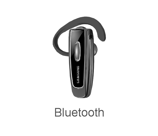
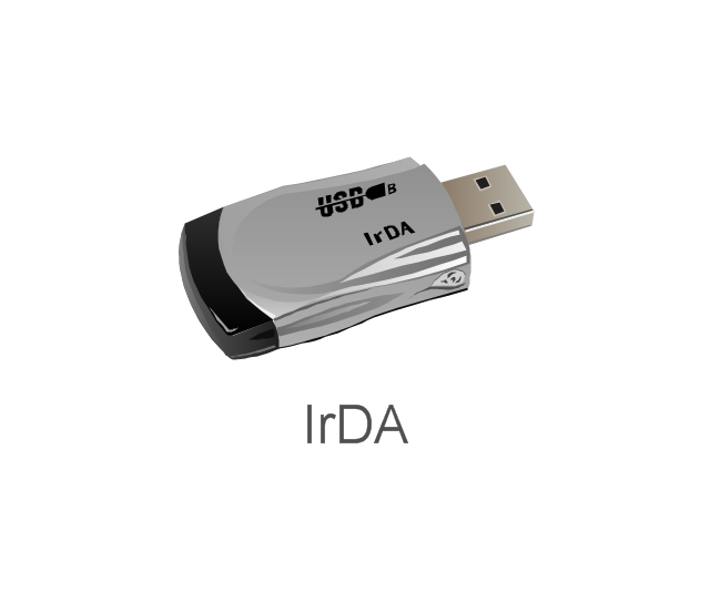
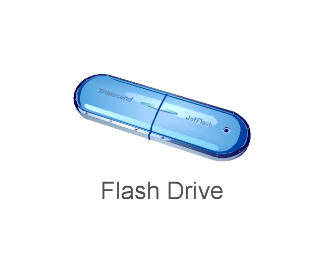
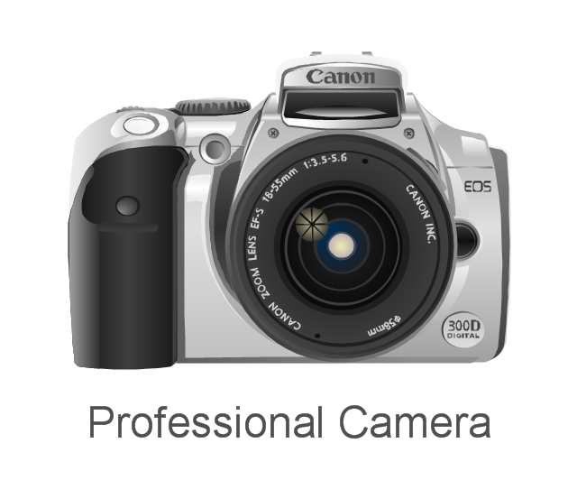
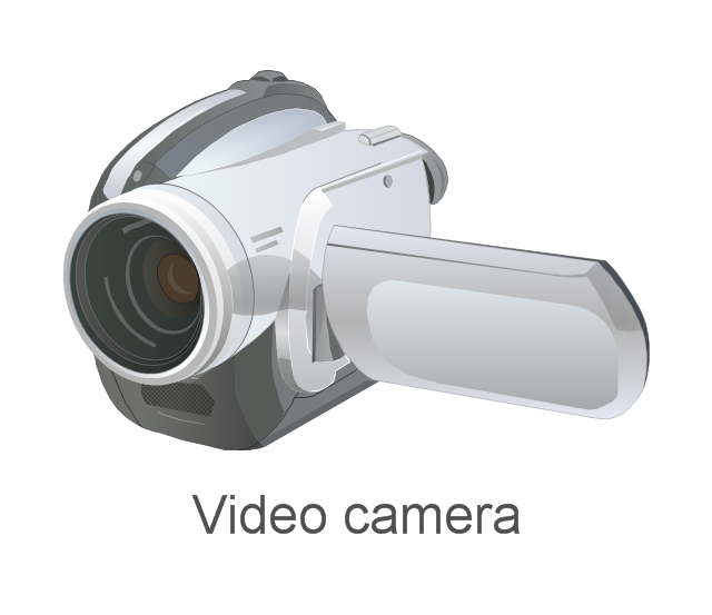
The vector stencils library "External digital devices" contains 15 clipart images of external digital devices and equipment for drawing computer network diagrams.
"Digital electronics, or digital (electronic) circuits, represent signals by discrete bands of analog levels, rather than by a continuous range. All levels within a band represent the same signal state. Relatively small changes to the analog signal levels due to manufacturing tolerance, signal attenuation or parasitic noise do not leave the discrete envelope, and as a result are ignored by signal state sensing circuitry. ...
Digital techniques are useful because it is easier to get an electronic device to switch into one of a number of known states than to accurately reproduce a continuous range of values. ...
An advantage of digital circuits when compared to analog circuits is that signals represented digitally can be transmitted without degradation due to noise. ...
In a digital system, a more precise representation of a signal can be obtained by using more binary digits to represent it. While this requires more digital circuits to process the signals, each digit is handled by the same kind of hardware. ...
Computer-controlled digital systems can be controlled by software, allowing new functions to be added without changing hardware. Often this can be done outside of the factory by updating the product's software. So, the product's design errors can be corrected after the product is in a customer's hands.
Information storage can be easier in digital systems than in analog ones. The noise-immunity of digital systems permits data to be stored and retrieved without degradation. ...
In a digital system, as long as the total noise is below a certain level, the information can be recovered perfectly." [Digital electronics. Wikipedia]
The clip art example "External digital devices - Vector stencils library" was created using the ConceptDraw PRO diagramming and vector drawing software extended with the Computer and Networks solution from the Computer and Networks area of ConceptDraw Solution Park.
www.conceptdraw.com/ solution-park/ computer-and-networks
The vector stencils library "Analog and digital logic" contains 40 element symbols of logic (threshold) gates, bistable current switches, current controllers, regulators, electrical generators, and amplifiers.
Use it for drawing the digital and analog functions in electronic circuit diagrams and electrical schematics.
"Analogue electronics (or analog in American English) are electronic systems with a continuously variable signal, in contrast to digital electronics where signals usually take only two different levels. The term "analogue" describes the proportional relationship between a signal and a voltage or current that represents the signal." [Analogue electronics. Wikipedia]
"Digital electronics, or digital (electronic) circuits, represent signals by discrete bands of analog levels, rather than by a continuous range. All levels within a band represent the same signal state. Relatively small changes to the analog signal levels due to manufacturing tolerance, signal attenuation or parasitic noise do not leave the discrete envelope, and as a result are ignored by signal state sensing circuitry.
In most cases the number of these states is two, and they are represented by two voltage bands: one near a reference value (typically termed as "ground" or zero volts) and a value near the supply voltage, corresponding to the "false" ("0") and "true" ("1") values of the Boolean domain respectively.
Digital techniques are useful because it is easier to get an electronic device to switch into one of a number of known states than to accurately reproduce a continuous range of values.
Digital electronic circuits are usually made from large assemblies of logic gates, simple electronic representations of Boolean logic functions." [Digital electronics. Wikipedia]
The example "Design elements - Analog and digital logic" was drawn using the ConceptDraw PRO diagramming and vector drawing software extended with the Electrical Engineering solution from the Engineering area of ConceptDraw Solution Park.
The vector stencils library "HVAC controls" contains 23 symbols of HVAC controls (sensors, actuators, timers, controllers, I/ O points).
"HVAC (... Heating, Ventilation and Air Conditioning) is a control system that applies regulation to a heating and/ or air conditioning system. ...
Central controllers and most terminal unit controllers are programmable, meaning the direct digital control program code may be customized for the intended use. The program features include time schedules, setpoints, controllers, logic, timers, trend logs, and alarms. The unit controllers typically have analog and digital inputs that allow measurement of the variable (temperature, humidity, or pressure) and analog and digital outputs for control of the transport medium (hot/ cold water and/ or steam). Digital inputs are typically (dry) contacts from a control device, and analog inputs are typically a voltage or current measurement from a variable (temperature, humidity, velocity, or pressure) sensing device. Digital outputs are typically relay contacts used to start and stop equipment, and analog outputs are typically voltage or current signals to control the movement of the medium (air/ water/ steam) control devices such as valves, dampers, and motors." [HVAC control system. Wikipedia]
Use the design elements library "HVAC controls" for drawing the HVAC system diagrams, controls drawings, and automated building control and environmental control system layuout floor plans using the ConceptDraw PRO diagramming and vector drawing software.
The shapes library "HVAC controls" is included in the HVAC Plans solution from the Building Plans area of ConceptDraw Solution Park.
 Engineering
This solution extends ConceptDraw PRO v9.4 with the ability to visualize industrial systems in electronics, electrical, chemical, process, and mechanical engineering.
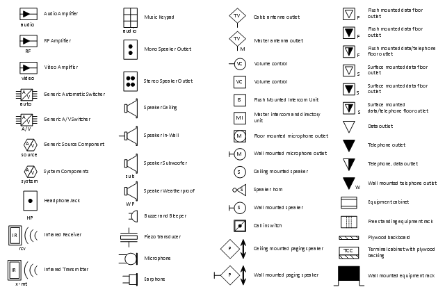
The vector stencils library "Video and audio" contains 50 symbols of audio and video devices and equipment.
Use the design elements library "Video and audio" for drawing audio and video system layouts, cabling floor plans, electrical circuit schematics and wiring diagrams of video and sound reproduction systems using the ConceptDraw PRO diagramming and vector drawing software.
Using the "Video and audio" library you can create video and audio engineering drawings and layout plans of your digital and analog, stereophonic (stereo), high fidelity (Hi-Fi, or hifi), quadraphonic, surround-sound, and home audio systems, home entertainment systems, home cinema (home theater, or home theatre), high-definition television (HDTV) and 3D television systems.
The shapes library "Video and audio" is included in the Electric and Telecom Plans solution from the Building Plans area of ConceptDraw Solution Park.
- Electronic Device
- Draw Two Examples Of Analogue Gadget And Digital Gadget
- External digital devices - Vector stencils library | Design elements ...
- Network Glossary Definition | External digital devices - Vector ...
- Design elements - Analog and digital logic | Electrical Symbols ...
- External digital devices - Vector stencils library | Design elements ...
- External digital devices - Vector stencils library | Design elements ...
- Circuits and Logic Diagram Software | Electrical Drawing Software ...
- Electrical Drawing Software and Electrical Symbols | Electrical ...
- Draw Digital Logic Circuits
- Design elements - Electrical circuits | Electrical Engineering ...
- Analogue Designed Drawing In Electrical Engineering
- External digital devices - Vector stencils library | Personal area (PAN ...
- Digital Communications Network. Computer and Network Examples ...
- How To use House Electrical Plan Software | Electrical Drawing ...
- State Diagram Example In Digital Logic Design
- Electrical Drawing Software and Electrical Symbols | Block Diagram ...
- Electrical Drawing Software and Electrical Symbols | Electrical ...
- External digital devices - Vector stencils library | Technology - Vector ...
- Electrical Drawing Software and Electrical Symbols | Circuits and ...
