Electrical Drawing Software and Electrical Symbols

Electrical Symbols, Electrical Diagram Symbols

The vector stencils library "Lamps, acoustics, measuring instruments" contains 35 element symbols of lamps, acoustic components, electrical measuring instruments.
Use these shapes for drawing electrical schematics and electronic circuit diagrams in the ConceptDraw PRO diagramming and vector drawing software extended with the Electrical Engineering solution from the Engineering area of ConceptDraw Solution Park.
www.conceptdraw.com/ solution-park/ engineering-electrical
Ammeter

Frequency meter

Voltmeter

Galvanometer

Oscilloscope

Synchroscope

Thermometer

Wavemeter

Standard bell with 1 line input

Single-stroke bell with 1 line input

Siren with 1 line input

Standard bell with 2 lines input

Bell with 2 lines input

Bell with 1 line input

Single-stroke bell with 2 lines input

Siren with 2 lines input

Buzzer with 1 line input

Buzzer with 2 lines input

Buzzer with 2 lines input

Buzzer with 1 line input

Indicating lamp with 1 line input

Non-indicating lamp with 1 line input

Indicating lamp with 2 lines input

Non-indicating lamp with 2 lines input

Signal lamp

Lamp

Fluorescent lamp 2 terminal

Fluorescent lamp 4 terminal

Speaker

Speaker with microphone

Microphone

Capacitor microphone

Push-pull microphone

Microphone with 1 line

Microphone with 2 lines

Electrical Symbols — Analog and Digital Logic

How To use House Electrical Plan Software


Electrical Symbols — Lamps, Acoustics, Readouts

Piping and Instrumentation Diagram Software

The vector stencils library "Switches and relays" contains 58 symbols of electrical contacts, switches, relays, circuit breakers, selectors, connectors, disconnect devices, switching circuits, current regulators, and thermostats for electrical devices.
"In electrical engineering, a switch is an electrical component that can break an electrical circuit, interrupting the current or diverting it from one conductor to another.
The most familiar form of switch is a manually operated electromechanical device with one or more sets of electrical contacts, which are connected to external circuits. Each set of contacts can be in one of two states: either "closed" meaning the contacts are touching and electricity can flow between them, or "open", meaning the contacts are separated and the switch is nonconducting. The mechanism actuating the transition between these two states (open or closed) can be either a "toggle" (flip switch for continuous "on" or "off") or "momentary" (push-for "on" or push-for "off") type.
A switch may be directly manipulated by a human as a control signal to a system, such as a computer keyboard button, or to control power flow in a circuit, such as a light switch. Automatically operated switches can be used to control the motions of machines, for example, to indicate that a garage door has reached its full open position or that a machine tool is in a position to accept another workpiece. Switches may be operated by process variables such as pressure, temperature, flow, current, voltage, and force, acting as sensors in a process and used to automatically control a system. ... A switch that is operated by another electrical circuit is called a relay. Large switches may be remotely operated by a motor drive mechanism. Some switches are used to isolate electric power from a system, providing a visible point of isolation that can be padlocked if necessary to prevent accidental operation of a machine during maintenance, or to prevent electric shock." [Switch. Wikipedia]
"A relay is an electrically operated switch. Many relays use an electromagnet to mechanically operate a switch, but other operating principles are also used, such as solid-state relays. Relays are used where it is necessary to control a circuit by a low-power signal (with complete electrical isolation between control and controlled circuits), or where several circuits must be controlled by one signal. The first relays were used in long distance telegraph circuits as amplifiers: they repeated the signal coming in from one circuit and re-transmitted it on another circuit. Relays were used extensively in telephone exchanges and early computers to perform logical operations.
A type of relay that can handle the high power required to directly control an electric motor or other loads is called a contactor. Solid-state relays control power circuits with no moving parts, instead using a semiconductor device to perform switching. Relays with calibrated operating characteristics and sometimes multiple operating coils are used to protect electrical circuits from overload or faults; in modern electric power systems these functions are performed by digital instruments still called "protective relays"." [Relay. Wikipedia]
The shapes example "Design elements - Switches and relays" was drawn using the ConceptDraw PRO diagramming and vector drawing software extended with the Electrical Engineering solution from the Engineering area of ConceptDraw Solution Park.
Switch and relay symbols

The vector stencils library "Fluid power equipment" contains 113 symbols of hydraulic and pneumatic equipment including pumps, motors, air compressors, cylinders, meters, gauges, and actuators.
Use it to design fluid power and hydraulic control systems in the ConceptDraw PRO diagramming and vector drawing software extended with the Mechanical Engineering solution from the Engineering area of ConceptDraw Solution Park.
www.conceptdraw.com/ solution-park/ engineering-mechanical
Use it to design fluid power and hydraulic control systems in the ConceptDraw PRO diagramming and vector drawing software extended with the Mechanical Engineering solution from the Engineering area of ConceptDraw Solution Park.
www.conceptdraw.com/ solution-park/ engineering-mechanical
Actuator (semi-rotary), pneumatic
,-pneumatic-fluid-power-equipment---vector-stencils-library.png--diagram-flowchart-example.png)
Actuator (semi-rotary), hydraulic
,-hydraulic-fluid-power-equipment---vector-stencils-library.png--diagram-flowchart-example.png)
Drive unit, pneumatic

Drive unit, hydraulic

Sgl-act. cylinder, pneum., left spring

Sgl-act. cylinder, pneum., right spring

Sgl-act. cylinder, pneumatic

Sgl-act. cylinder, hydr., left spring

Sgl-act. cylinder, hydr., right spring

Sgl-act. cylinder, hydraulic

Dbl-act. cylinder, pneumatic

Dbl-act. cylinder, pneum., sgl cushion

Dbl-act. cylinder, pneum., dbl cushion

Dbl-act. cylinder, pneum., adjustable

Dbl-act. cylinder, pneum., sgl cushion, adj.

Dbl-act. cylinder, pneum., dbl cushion, adj.

Dbl-act. cylinder, hydraulic

Dbl-act. cylinder, hydr., sgl cushion

Dbl-act. cylinder, hydr., dbl cushion

Dbl-act. cylinder, hydr., adjustable

Dbl-act. cylinder, hydr., sgl cushion, adj.

Dbl-act. cylinder, hydr., dbl cushion, adj.

Dbl-act. cylinder, magnetic

Dbl-act. cylinder, magn., sgl cushion

Dbl-act. cylinder, magn., dbl cushion

Dbl-act. cylinder, magn., adjustable

Dbl-act. cylinder, magn., sgl cushion, adj.

Dbl-act. cylinder, magn., dbl cushion, adj.

Dbl-act. dbl-end. cylinder, pneumatic

Dbl-act. dbl-end. cylinder, pneum., sgl cushion

Dbl-act. dbl-end. cylinder, pneum., dbl cushion

Dbl-act. dbl-end. cylinder, pneum., adjustable

Dbl-act. dbl-end. cylinder, pneum., sgl cushion, adj.

Dbl-act. dbl-end. cylinder, pneum., dbl cushion, adj.

Dbl-act. dbl-end. cylinder, hydraulic

Dbl-act. dbl-end. cylinder, hydr., sgl cushion

Dbl-act. dbl-end. cylinder, hydr., dbl cushion

Dbl-act. dbl-end. cylinder, hydr., adjustable

Dbl-act. dbl-end. cylinder, hydr., sgl cushion, adj.

Dbl-act. dbl-end. cylinder, hydr., dbl cushion, adj.

Telescopic cylinder, pneum., dbl-act.

Telescopic cylinder, hydr., dbl-act.

Telescopic cylinder, pneum., sgl-act.

Telescopic cylinder, hydr., sgl-act.

Actuator, hydraulic-pneumatic

Actuator, pneumatic-hydraulic

Intensifier, pneumatic

Intensifier, hydraulic

Intensifier, hydraulic-pneumatic

Intensifier, pneumatic-hydraulic

Intensifier, pneumatic-hydraulic

Intensifier, hydraulic-pneumatic

Actuator, pneumatic-hydraulic

Actuator, hydraulic-pneumatic

Accumulator

Accumulator, gas loaded

Accumulator, spring loaded

Accumulator, auxiliary gas bottle

Air receiver

Energy source, pneumatic

Energy source, hydraulic

Energy source, electric motor

Energy source, non-electric prime mover

Vented reservoir

Sealed reservoir

Filter

Filter, magnetic element

Filter, contamination indicator

Automatic drain filter separator

Manual drain filter separator

Separator, automatic drain

Separator, manual drain

Air dryer

Lubricator

Air service unit, filter, separator

Air service unit, separator

Air service unit, filter

Air service unit

Liquid cooler

Gas cooler

Cooler

Liquid heater

Gas heater

Heater

Liquid temperature controller

Gas temperature controller

Temperature controller

Liquid temperature controller 2

Gas temperature controller 2

Temperature controller 2

Pressure indicator

Pressure gauge

Differential pressure gauge

Thermometer

Liquid level measuring instrument

Flow indicator

Flow meter

Integrating flow meter

Tachometer

Torque measurement equipment

Pressure switch

Limit switch

Transducer

Pulse counter

Pulse counter 2

Silencer

Drain (inlet below fluid, drain line)
-fluid-power-equipment---vector-stencils-library.png--diagram-flowchart-example.png)
Drain (inlet below fluid, return line)
-fluid-power-equipment---vector-stencils-library.png--diagram-flowchart-example.png)
Drain (inlet above fluid, drain line)
-fluid-power-equipment---vector-stencils-library.png--diagram-flowchart-example.png)
Drain (inlet above fluid, return line)
-fluid-power-equipment---vector-stencils-library.png--diagram-flowchart-example.png)
Oil tank

Oil tank, empty

Air compressor

The vector stencils library "Instruments" contains 72 symbols of control instruments and measuring devices: meters and gauges, and callouts, text boxes, and inserts.
Use these shapes to create annotated process flow diagrams (PFD), flow control, manufacturing processes, and distribution system diagrams.
"Process control is an engineering discipline that deals with architectures, mechanisms and algorithms for maintaining the output of a specific process within a desired range.
Process control is extensively used in industry and enables mass production of continuous processes such as oil refining, paper manufacturing, chemicals, power plants and many other industries. Process control enables automation, with which a small staff of operating personnel can operate a complex process from a central control room." [Process control. Wikipedia]
The example "Design elements - Instruments" was created using the ConceptDraw PRO diagramming and vector drawing software extended with the Chemical and Process Engineering solution from the Engineering area of ConceptDraw Solution Park.
Process control instrument symbols

Chemical Engineering

The vector stencils library "Instruments" contains 72 symbols of control instruments and measuring devices: meters and gauges, and callouts, text boxes, and inserts.
Use these shapes to create annotated process flow diagrams (PFD), flow control, manufacturing processes, and distribution system diagrams in the ConceptDraw PRO software extended with the Chemical and Process Engineering solution from the Chemical and Process Engineering area of ConceptDraw Solution Park.
www.conceptdraw.com/ solution-park/ engineering-chemical-process
Indicator local

Indicator remote

Indicator auxiliary

CRT local

CRT remote

CRT auxiliary

PLC local

PLC auxiliary

PLC remote

Computer local

Computer auxiliary

Computer remote

Light local

Light remote

Light auxiliary

Indicator auxiliary (dashed)
-instruments---vector-stencils-library.png--diagram-flowchart-example.png)
Indicator remote (dashed)
-instruments---vector-stencils-library.png--diagram-flowchart-example.png)
Steam traced auxiliary

Steam traced remote

Steam traced local

Level meter auxiliary

Level meter remote

Level meter local

Pressure gauge diaphragm

Pressure gauge

Pressure gauge liquid filled

Strain gauge

Thermometer bi-metallic

Thermometer gas

Thermometer general

Thermometer glass

Thermometer liquid

Thermometer resistance

Thermometer thermocouple

Flowmeter electromagnetic

Flowmeter general

Flowmeter nozzle

Flowmeter orifice

Flowmeter positive displacement

Flowmeter turbine

Flowmeter variable area

Flowmeter Venturi

Level meter capacitive

Level meter conductive

Level meter displacer

Level meter float

Level meter general

Level meter sonic

Indicator analoque

Indicator digital

Indicator general

Recorder analoque

Recorder digital

Recorder general

Converter

Converter 2 (1st half filled)
-instruments---vector-stencils-library.png--diagram-flowchart-example.png)
Converter 3 (2nd half filled)
-instruments---vector-stencils-library.png--diagram-flowchart-example.png)
Venturi

Venturi (pressure taps)
-instruments---vector-stencils-library.png--diagram-flowchart-example.png)
Flowmeter

Rotameter

Vortex sensor

Propeller meter

Generic utility

Operator box

Operator box 2 (1st half filled)
-instruments---vector-stencils-library.png--diagram-flowchart-example.png)
Operator box 3 (2nd half filled)
-instruments---vector-stencils-library.png--diagram-flowchart-example.png)
AND gate

OR gate

NOT gate

Correcting element

Diamond

This cafe electrical floor plan sample shows the outlet and switch layout.
"An electrical drawing, is a type of technical drawing that shows information about power, lighting, and communication for an engineering or architectural project. Any electrical working drawing consists of "lines, symbols, dimensions, and notations to accurately convey an engineering's design to the workers, who install the electrical system on the job".
A complete set of working drawings for the average electrical system in large projects usually consists of:
(1) A plot plan showing the building's location and outside electrical wiring.
(2) Floor plans showing the location of electrical systems on every floor.
(3) Power-riser diagrams showing panel boards.
(4) Control wiring diagrams.
(5) Schedules and other information in combination with construction drawings.
Electrical drafters prepare wiring and layout diagrams used by workers who erect, install, and repair electrical equipment and wiring in communication centers, power plants, electrical distribution systems, and buildings." [Electrical drawing. Wikipedia]
The outlet and switch layout example "Cafe electrical floor plan" was created using the ConceptDraw PRO diagramming and vector drawing software extended with the Electric and Telecom Plans solution from the Building Plans area of ConceptDraw Solution Park.
Outlet and switch layout

Work Order Process Flowchart. Business Process Mapping Examples

 Medical Illustrations
Medical Illustrations solution including the set of professionally developed examples and samples dedicated to medicine, large variety of ready-to-use vector objects and icons of diagnostic equipment, treatment equipment, medical instruments, tools and devices, medical professionals and health workers of different medical specialties, medical procedures and patients, medical pictograms and medical symbols, among which are the famous red cross symbol, heartbeat symbol, doctor symbol, and many others, is a perfect help in questions of medical illustration and medical imaging, creation professional-looking, colorful and attractive Medical illustrations, Medical diagrams and infographics, slides for presentations in a field of medicine and health care, depicting the medical facts, the information about varied diseases and ways of medical diagnosis, methods of prevention and treatment diseases.
The vector stencils library "Fluid power valves" contains 93 symbols of pre-made hydraulic and pneumatic valves, including directional control valves, flow control valves, pressure control valves, and electrohydraulic and electropneumatic valves.
"Control valves are valves used to control conditions such as flow, pressure, temperature, and liquid level by fully or partially opening or closing in response to signals received from controllers that compare a "setpoint" to a "process variable" whose value is provided by sensors that monitor changes in such conditions.
The opening or closing of control valves is usually done automatically by electrical, hydraulic or pneumatic actuators. Positioners are used to control the opening or closing of the actuator based on electric, or pneumatic signals.
A control valve consists of three main parts in which each part exist in several types and designs: Valve's actuator, Valve's positioner, Valve's body.
" [Control valves. Wikipedia]
The shapes example "Design elements - Fluid power valves" was created using the ConceptDraw PRO diagramming and vector drawing software extended with the Mechanical Engineering solution from the Engineering area of ConceptDraw Solution Park.
Fluid power valve symbols

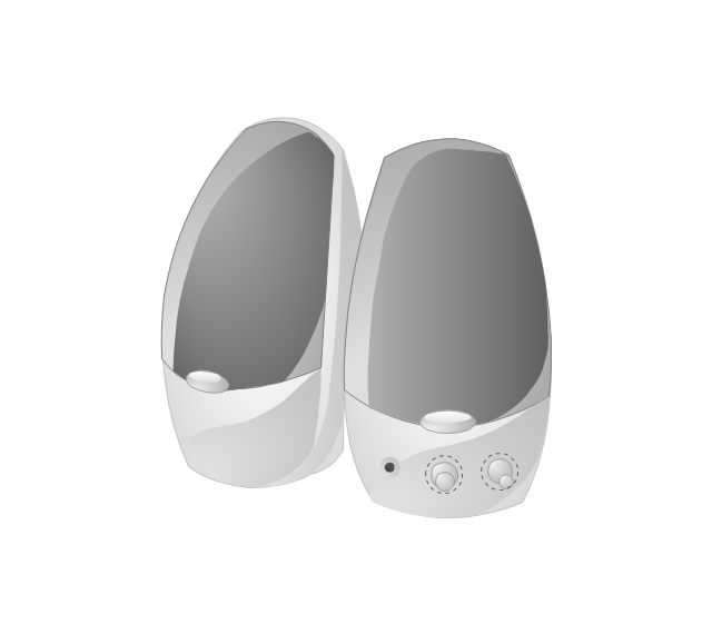
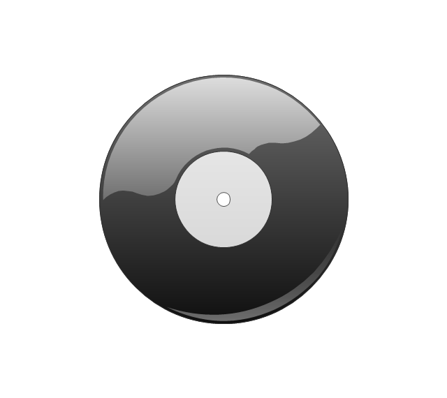
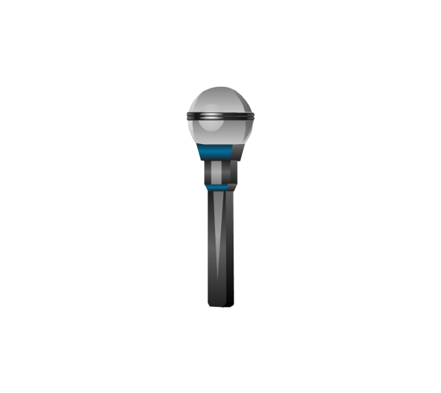
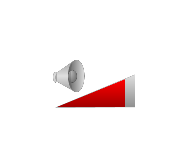
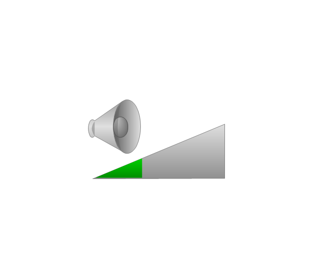
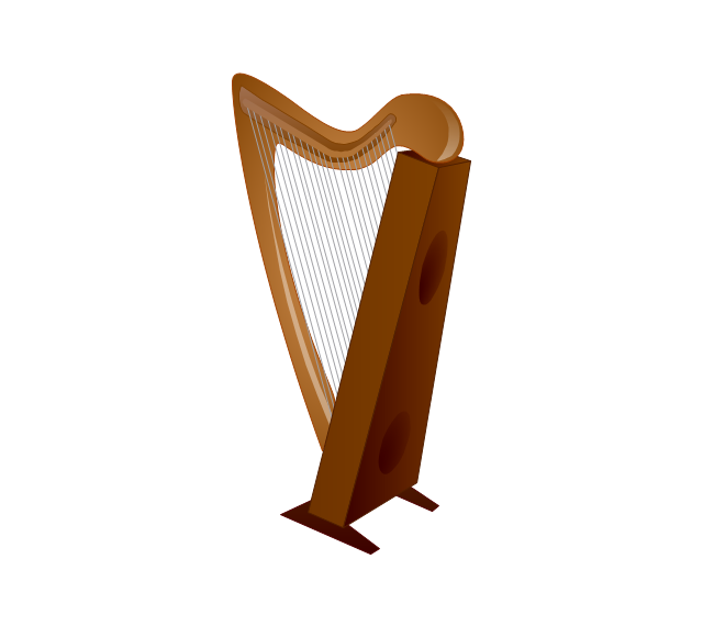
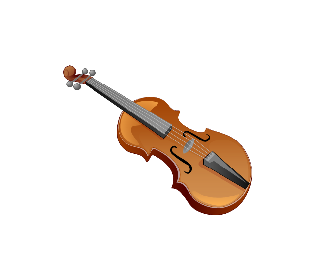
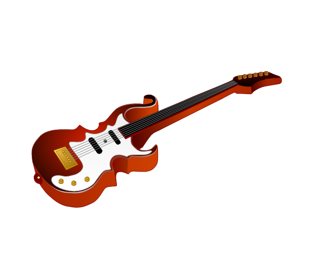
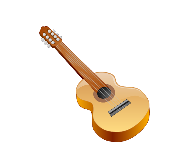
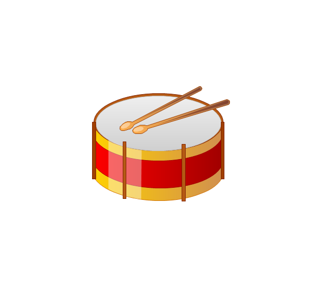
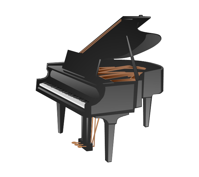
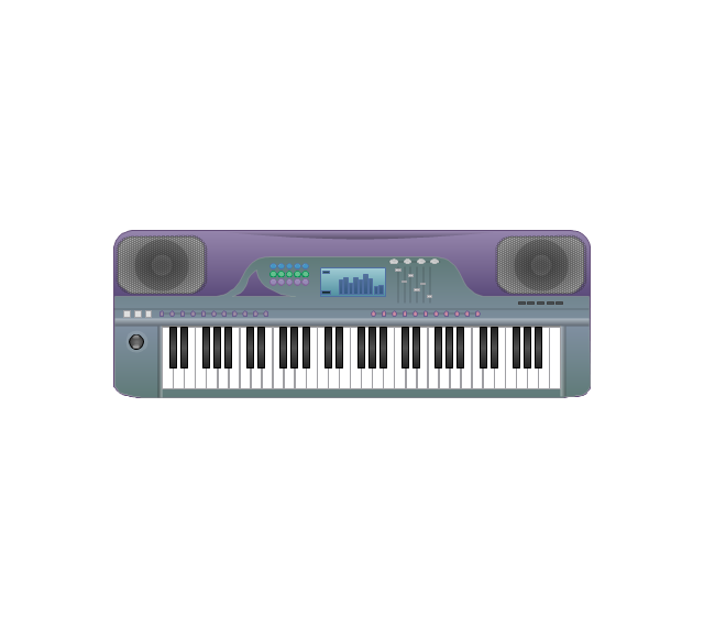
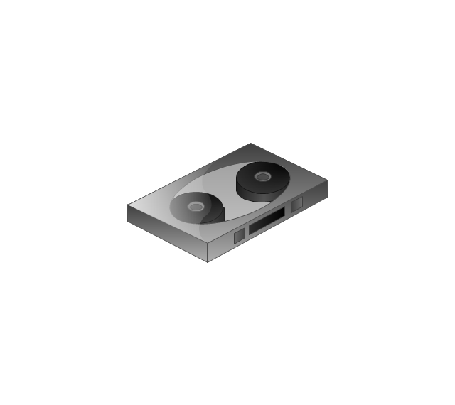
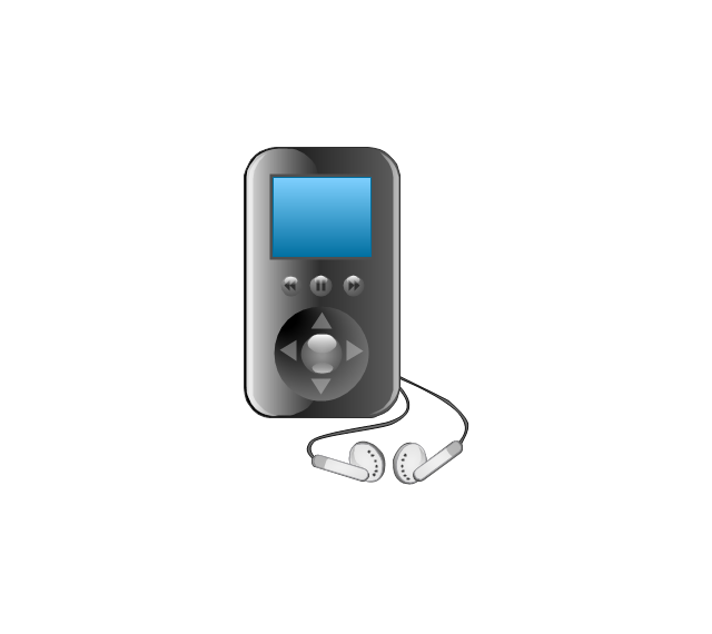
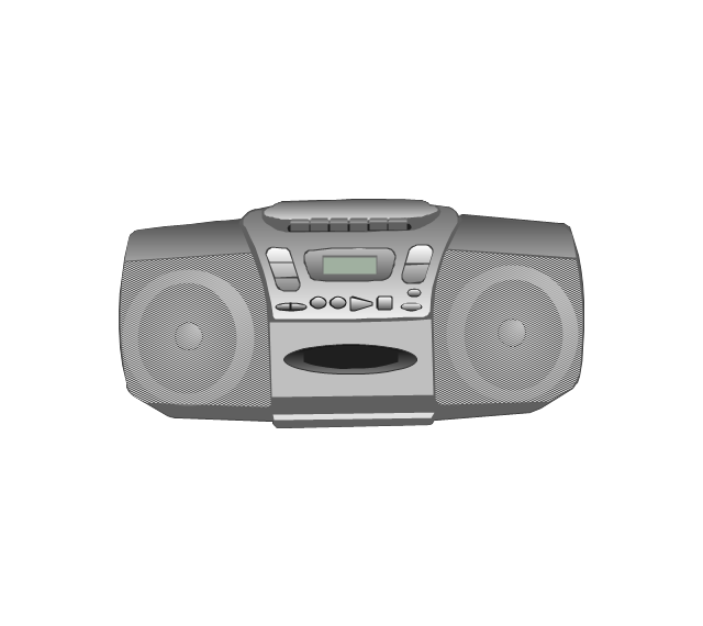
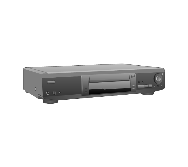
The vector stencils library "Music" contains 28 clipart images of musical devices, instruments and note signs for drawing illustrations.
"Music notation or musical notation is any system used to visually represent aurally perceived music through the use of written symbols, including ancient or modern musical symbols. Although many ancient cultures used symbols to represent melodies, none of them is nearly as comprehensive as written language, limiting the knowledge of ancient music to a few fragments. Comprehensive music notation began to be developed in Europe in the Middle Ages and has been adapted to many kinds of music worldwide." [Musical notation. Wikipedia]
The clip art example "Music - Vector stencils library" was created using the ConceptDraw PRO diagramming and vector drawing software extended with the Artwork solution from the Illustration area of ConceptDraw Solution Park.
www.conceptdraw.com/ solution-park/ illustrations-artwork
Speakers
Mute

Vinyl record
Compact Disk

Note

Two beamed notes

Eighth note

Headphones

Microphone
Loudness
Silent
Harp
Violin
Electric guitar
Acoustic Guitar
Drum
Piano
Synthesizer
Compact Cassette
Mobile digital media player
Boom Box
CD-player
Jazz

Pop

Rap

Techno

Rock

Trance

The vector stencils library "Valve assembly" contains 141 symbols of pressure and flow regulators, flow direction indicators, controls, and symbols to design flow paths of control valves.
Use these valve assembly shapes to design the engineering drawings of hydraulic and pneumatic valve assemblies in fluid power systems.
"Control valves are valves used to control conditions such as flow, pressure, temperature, and liquid level by fully or partially opening or closing in response to signals received from controllers that compare a "setpoint" to a "process variable" whose value is provided by sensors that monitor changes in such conditions.
The opening or closing of control valves is usually done automatically by electrical, hydraulic or pneumatic actuators. Positioners are used to control the opening or closing of the actuator based on electric, or pneumatic signals.
A control valve consists of three main parts in which each part exist in several types and designs: Valve's actuator, Valve's positioner, Valve's body.
" [Control valves. Wikipedia]
The shapes example "" was created using the ConceptDraw PRO diagramming and vector drawing software extended with the Mechanical Engineering solution from the Engineering area of ConceptDraw Solution Park.
Valve assembly symbols

The vector stencils library "Transmission paths" contains 43 symbols of power transmission paths, electronic circuits, bus connectors and elbows, terminals, junctions, and concentrators.
Use it to annotate electrical diagrams, electronic schematics and circuit diagrams.
"A physical medium in data communications is the transmission path over which a signal propagates.
Many transmission media are used as communications channel.
For telecommunications purposes in the United States, Federal Standard 1037C, transmission media are classified as one of the following:
(1) Guided (or bounded) - waves are guided along a solid medium such as a transmission line.
(2) Wireless (or unguided) - transmission and reception are achieved by means of an antenna.
One of the most common physical medias used in networking is copper wire. Copper wire to carry signals to long distances using relatively low amounts of power. The unshielded twisted pair (UTP) is eight strands of copper wire, organized into four pairs.
Another example of a physical medium is optical fiber, which has emerged as the most commonly used transmission medium for long-distance communications. Optical fiber is a thin strand of glass that guides light along its length.
Multimode and single mode are two types of commonly used optical fiber. Multimode fiber uses LEDs as the light source and can carry signals over shorter distances, about 2 kilometers. Single mode can carry signals over distances of tens of miles.
Wireless media may carry surface waves or skywaves, either longitudinally or transversely, and are so classified.
In both communications, communication is in the form of electromagnetic waves. With guided transmission media, the waves are guided along a physical path; examples of guided media include phone lines, twisted pair cables, coaxial cables, and optical fibers. Unguided transmission media are methods that allow the transmission of data without the use of physical means to define the path it takes. Examples of this include microwave, radio or infrared. Unguided media provide a means for transmitting electromagnetic waves but do not guide them; examples are propagation through air, vacuum and seawater.
The term direct link is used to refer to the transmission path between two devices in which signals propagate directly from transmitters to receivers with no intermediate devices, other than amplifiers or repeaters used to increase signal strength. This term can apply to both guided and unguided media.
A transmission may be simplex, half-duplex, or full-duplex.
In simplex transmission, signals are transmitted in only one direction; one station is a transmitter and the other is the receiver. In the half-duplex operation, both stations may transmit, but only one at a time. In full duplex operation, both stations may transmit simultaneously. In the latter case, the medium is carrying signals in both directions at same time." [Transmission medium. Wikipedia]
The shapes example "Design elements - Transmission paths" was drawn using the ConceptDraw PRO diagramming and vector drawing software extended with the Electrical Engineering solution from the Engineering area of ConceptDraw Solution Park.
Transmission path symbols

The vector stencils library Initiation and annunciation contains 9 symbols of Fire Alarm Control Panel (FACP) or Fire Alarm Control Unit (FACU) elements, triggering devices, audible alarm systems, timers, security control equipment, and recording devices.
"A Fire Alarm Control Panel (FACP), or Fire Alarm Control Unit (FACU), is the controlling component of a Fire Alarm System. The panel receives information from environmental sensors designed to detect changes associated with fire, monitors their operational integrity and provides for automatic control of equipment, and transmission of information necessary to prepare the facility for fire based on a predetermined sequence. The panel may also supply electrical energy to operate any associated sensor, control, transmitter, or relay. There are four basic types of panels: coded panels, conventional panels, addressable panels, and multiplex systems." [Fire alarm control panel. Wikipedia]
Use the shapes library Initiation and annunciation to draw layout floor plans, communications schematics and wiring diagrams of security systems using the ConceptDraw PRO diagramming and vector drawing software.
The design elements library Initiation and annunciation is included in the Security and Access Plans solution from the Building Plans area of ConceptDraw Solution Park.
Initiation and annunciation symbols

- Design elements - Lamps, acoustics, measuring instruments ...
- Electrical Symbols , Electrical Diagram Symbols | Electrical Symbols ...
- Types Of Electrical Measuring Instruments
- Symbol On Measuring Instruments
- Electrical Symbol Of Instrument
- Design elements - Instruments | Instruments - Vector stencils library ...
- Electrical Symbols — Thermo | Electrical Symbols — Resistors ...
- Electrical Symbols , Electrical Diagram Symbols | Electrical Drawing ...
- Electrical Symbols , Electrical Diagram Symbols | Electrical Drawing ...
- Electrical Symbols , Electrical Diagram Symbols | Electrical Symbols ...
- Electrical Symbols , Electrical Diagram Symbols | Electrical Symbols ...
- Electrical Symbols — Thermo | Design elements - Lamps, acoustics ...
- Design elements - Lamps, acoustics, measuring instruments ...
- Diagram Of Electrical Measuring Instruments
- Electrical Symbols For Electrical Instruments
- Design elements - Lamps, acoustics, measuring instruments ...
- Electrical Symbols , Electrical Diagram Symbols | Process Flow ...
- Electrical Symbols — Lamps, Acoustics, Readouts | Electrical ...
- Design elements - Lamps, acoustics, measuring instruments | HVAC ...
- Office Layout | Principle Of Electrical Measuring Instruments