How To use House Electrical Plan Software


Television networks. Computer and Network Examples


The design elements library "Cable TV" contains 64 symbols of CATV network equipment.
"Cable television is a system of distributing television programs to subscribers via radio frequency (RF) signals transmitted through coaxial cables or light pulses through fiber-optic cables. This contrasts with traditional broadcast television (terrestrial television) in which the television signal is transmitted over the air by radio waves and received by a television antenna attached to the television. FM radio programming, high-speed Internet, telephone service, and similar non-television services may also be provided through these cables.
The abbreviation CATV is often used for cable television." [Cable television. Wikipedia]
Use the shapes library "Cable TV" to draw CATV system design floor plans, network topology diagrams, wiring diagrams and cabling layout schemes using the ConceptDraw PRO diagramming and vector drawing software.
The vector stencils library "Cable TV" is included in the Electric and Telecom Plans solution from the Building Plans area of ConceptDraw Solution Park.
Cable TV symbols
.png--diagram-flowchart-example.png)
The vector stenvils library "Outlets" contains 57 symbols of electrical outlets.
Use these shapes for drawing building interior design, electrical floor plans and layouts of AC power plugs and sockets in the ConceptDraw PRO diagramming and vector drawing software.
The vector stencils library "Outlets" is included in the Electric and Telecom Plans solution from the Building Plans area of ConceptDraw Solution Park.
Single Outlet

Single Outlet and Switch

Emergency Circuit Single Outlet

Duplex Convenience Outlet

Emergency Circuit Duplex Outlet

Weatherproof Convenience Outlet

Range Outlet

Switch and Convenience Outlet

Radio and Convenience Outlet

Radio Outlet

Dedicated Duplex Outlet

Duplex Ground Fault Interrupter

Split Wired Duplex Outlet

240v Outlet

Floor Mounted Outlet

Floor Special-purpose Outlet

Heavy Duty Outlet

Heavy Duty Outlet with Convenience Outlet

Triplex Outlet

Split Wired Triplex Outlet

Quadruplex Outlet

Emergency Circuit Quadruplex Outlet

Special-purpose Outlet

Duplex Special-purpose Outlet

Special-purpose connection or provision for connection

Multi-outlet Assembly

Data/voice, Power Floor Mounted Outlet

Clock Hanger Outlet, Mounted

Blanked Outlet

Drop Outlet

Electrical Outlet

Fan Outlet

Junction Box

Lamp Holder

Lamp holder with pull switch

Pull Switch

Vapor discharge lamp outlet

Exit Light Outlet

Floor Receptacle

Telephone outlet

Floor Phone Outlet

Wall Phone Outlet

Weatherproof Phone Outlet

Phone Feed

Computer Data Outlet

Television outlet

Floor TV Outlet

TV Feed

Weatherproof TV Outlet

TV and Phone Outlet

Door Phone Outlet

Fax Outlet

Fiber Outlet

Multi-Purpose Outlet

Local Area Network Outlet

Wall Mounted Data Outlet

Wall Mounted Data/Telephone Outlet

Electrical Symbols — VHF UHF SHF

The vector stencils library "Audio and video connectors" contains 94 symbols of audio and video connectors (TRS, TS, XLR, microphone, headphone, TOSLINK, DVI, VGA, DFP, S-Video, RCA, display port, HDMI, Thunderbolt, coaxial TV, F connector, MIDI) and device silhouettes.
Use these jacks and plugs clipart icons for drawing hook up diagrams.
"Audio connectors and video connectors are electrical connectors (or optical connectors) for carrying audio signal and video signal, of either analog or digital format. Analog A/ V connectors often use shielded cables to inhibit radio frequency interference (RFI) and noise." [Audio and video connector. Wikipedia]
"The existence of many different audio and video standards necessitates the definition of hardware interfaces, which define the physical characteristics of the connections between electrical equipment. This includes the types and numbers of wires required along with the strength and frequency of the signal. It also includes the physical design of the plugs and sockets.
An interface may define a connector that is used only by that interface (e.g., DVI) or may define a connector that is also used by another interface; for example, RCA connectors are defined both by the composite video and component video interfaces.
Audio connectors and video connectors are electrical connectors (or optical connectors) for carrying audio signal and video signal, of either analog or digital format. Analog A/ V connectors often use shielded cables to inhibit radio frequency interference (RFI) and noise.
Since both analog and digital signals are used with some styles of connectors, knowledge of the interface used is necessary for a successful transfer of signals. Some interface types use only a distinctive connector or family of connectors, to ensure compatibility. Especially with analog interfaces, physically interchangeable connectors may not carry compatible signals.
Some of these connectors, and other types of connectors, are also used at radio frequency (RF) to connect a radio or television receiver to an antenna or to a cable system..." [Audio and video interfaces and connectors. Wikipedia]
The clipart icons example "Design elements - Audio and video connectors" was created using the ConceptDraw PRO diagramming and vector drawing software extended with the Audio and Video Connectors solution from the Engineering area of ConceptDraw Solution Park.
Audio and video jacks and plugs

Electrical Symbols — Electron Tubes

Electrical Symbols — Transmission Paths

Physical Security Plan

Electrical Symbols — Semiconductor

The vector stencils library "Electrical and telecom" contains 83 symbols of electrical and telecommunication equipment.
Use these shapes for drawing electrical and telecom system design floor plans, cabling layout schemes, and wiring diagrams in the ConceptDraw PRO diagramming and vector drawing software.
The vector stencils library "Electrical and telecom" is included in the Electric and Telecom Plans solution from the Building Plans area of ConceptDraw Solution Park.
Luminaire ceiling mount

Enclosed ceiling luminaire

Wall light

1-light bar

2-light bar

4-light bar

6-light bar

8-light bar

Down lighter

Outdoor lightning

Outdoor lightning, bollard

Batten fluorescent, 1 lamp

Batten fluorescent, 2 lamps

Batten fluorescent, 3 lamps

Batten fluorescent, 4 lamps

Surface Fluorescent Light

Modular fluorescent fitting

Modular fluorescent fitting, inverter

Modular fluorescent fitting 2

Pull-cord switch

Emergency light

Emergency light 2

Emergency sign

Switch

Switch, 1 pole

Switch, 2 pole

Switch, 2-way

Multi-switch

Switch, intermediate

Dimmer switch

Dimmer switch 2

Socket

Socket 2

Switched socket

Switched socket 2

Double socket

Double socket 2

Socket outlet

Telephone outlet

Telephone outlet 2

Stereo outlet

Television outlet

Service panel, surface

Service panel, inset

Thermostat

Ceiling fan

Hold open unit

Detector

Fire alarm

City Fire Alarm Station

Fire Alarm Station

Fire Alarm Bell

Fire Alarm Central Station

Automatic Fire Alarm Device

Main control

Ground

Doorbell

Push Button

Buzzer

Annunciator

Horn

Maid's Signal Plug

Signal Central Station

Doorbell Chime

Doorbell Transformer

Magnetic Door Hold

Intercom

Telephone Key System

Digital Satellite System

Inside Antenna

Outside Antenna

Electric Motors

Single Phase

Three of Poly Phase

Wall Mounted Electrical Junction Box for Hardware

Wall Mounted Telephone/Data Junction Box for Hardware

Card Reader Access System

Emergency Release Button

Motion Sensor

Electric Door Opener

Watchman's Station

Watchman's Central Station

Battery

The vector stencils library "Video and audio" contains 50 symbols of audio and video devices and equipment.
Use the design elements library "Video and audio" for drawing audio and video system layouts, cabling floor plans, electrical circuit schematics and wiring diagrams of video and sound reproduction systems using the ConceptDraw PRO diagramming and vector drawing software.
Using the "Video and audio" library you can create video and audio engineering drawings and layout plans of your digital and analog, stereophonic (stereo), high fidelity (Hi-Fi, or hifi), quadraphonic, surround-sound, and home audio systems, home entertainment systems, home cinema (home theater, or home theatre), high-definition television (HDTV) and 3D television systems.
The shapes library "Video and audio" is included in the Electric and Telecom Plans solution from the Building Plans area of ConceptDraw Solution Park.
Video and audio symbols

Electrical Symbols — Semiconductor Diodes

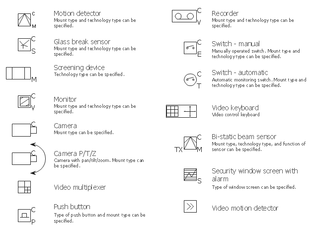
The vector stencils library Video surveillance contains 15 symbols of electronic closed-circuit television (CCTV) equipment, digital video cameras and recording devices and covert video equipment.
"Closed-circuit television (CCTV) is the use of video cameras to transmit a signal to a specific place, on a limited set of monitors. It differs from broadcast television in that the signal is not openly transmitted, though it may employ point to point (P2P), point to multipoint, or mesh wireless links. Though almost all video cameras fit this definition, the term is most often applied to those used for surveillance in areas that may need monitoring such as banks, casinos, airports, military installations, and convenience stores.
In industrial plants, CCTV equipment may be used to observe parts of a process from a central control room, for example when the environment is not suitable for humans. CCTV systems may operate continuously or only as required to monitor a particular event. A more advanced form of CCTV, utilizing digital video recorders (DVRs), provides recording for possibly many years, with a variety of quality and performance options and extra features (such as motion-detection and email alerts). More recently, decentralized IP cameras, some equipped with megapixel sensors, support recording directly to network-attached storage devices, or internal flash for completely stand-alone operation. Surveillance of the public using CCTV is particularly common in many areas around the world." [Closed-circuit television. Wikipedia]
Use the design elements library Video surveillance to design the layout plans of security and access systems, and internal and external video surveillance and security control monitoring systems using the ConceptDraw PRO diagramming and vector drawing software.
The shapes library Video surveillance is included in the Security and Access Plans solution from the Building Plans area of ConceptDraw Solution Park.
Video surveillance symbols
Electrical Symbols — Thermo

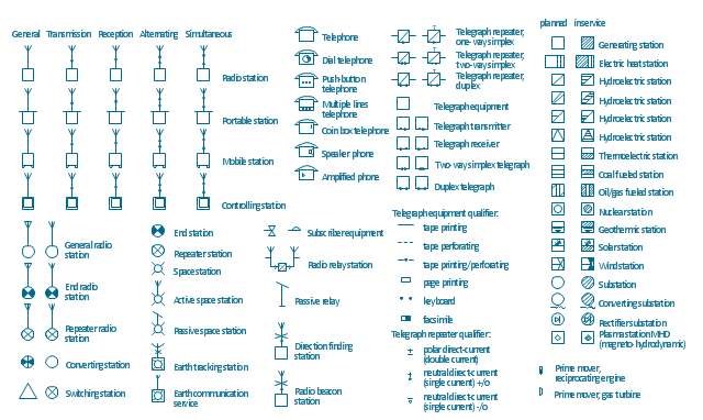
The vector stencils library "Stations" contains 110 symbols of communications equipment, generating, transmitting and receiving stations; substations; satellites; and power plants for power generation and distribution and radio relay systems.
"A power station (also referred to as a generating station, power plant, powerhouse or generating plant) is an industrial facility for the generation of electric power. At the center of nearly all power stations is a generator, a rotating machine that converts mechanical power into electrical power by creating relative motion between a magnetic field and a conductor. The energy source harnessed to turn the generator varies widely. It depends chiefly on which fuels are easily available, cheap enough and on the types of technology that the power company has access to. Most power stations in the world burn fossil fuels such as coal, oil, and natural gas to generate electricity, and some use nuclear power, but there is an increasing use of cleaner renewable sources such as solar, wind, wave and hydroelectric." [Power station. Wikipedia]
"Radio broadcasting is a one-way wireless transmission over radio waves intended to reach a wide audience. Stations can be linked in radio networks to broadcast a common radio format, either in broadcast syndication or simulcast or both. Audio broadcasting also can be done via cable radio, local wire television networks, satellite radio, and internet radio via streaming media on the Internet.
The signal types can be either analog audio or digital audio." [Radio broadcasting. Wikipedia]
The shapes example "Design elements - Stations" was drawn using the ConceptDraw PRO diagramming and vector drawing software extended with the Electrical Engineering solution from the Engineering area of ConceptDraw Solution Park.
Power and radio station symbols
Electrical Symbols — Delay Elements

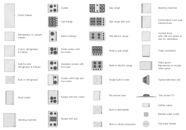
The vector stencils library Appliances contains 36 symbols of kitchen appliances, laundry appliances, stoves, cooking appliances, and laundry equipment.
Use the shapes library Appliances to draw equipment layouts and interior design floor plans of kitchens, laundry rooms, utility rooms using the ConceptDraw PRO diagramming and vector drawing software.
"Home appliances are electrical/ mechanical machines which accomplish some household functions, such as cooking or cleaning. Home appliances can be classified into:
Major appliances, or White goods;
Small appliances, or Brown goods;
Consumer electronics, or Shiny goods.
White goods/ major appliances comprise major household appliances and may include: air conditioner, dishwasher, clothes dryer, drying cabinet, freezer, refrigerator, kitchen stove, water heater, washing machine, trash compactor, microwave ovens and induction cookers.
Brown goods/ small appliances are typically small household electrical entertainment appliances such as: TV sets, CD and DVD players, camcorders, still cameras, clocks, alarm clocks, video game consoles, HiFi and home cinema, telephones and answering machines.
Consumer electronics (abbreviated CE) are electronic equipment intended for everyday use, most often in entertainment, communications and office productivity. Main products include radio receivers, television sets, MP3 players, video recorders, DVD players, digital cameras, camcorders, personal computers, video game consoles, telephones and mobile phones." [Home appliance. Wikipedia]
The design elements library Appliances is provided by the Floor Plans solution from the Building Plans area of ConceptDraw Solution Park.
Electrical Symbols — Electrical Circuits

The vector stencils library "VHF UHF SHF" contains 52 symbols for VHF, UHF, and SHF circuit design, including capacitance measurers, nonreciprocal devices, modulators, phase shifters, field polarization devices, and filters.
"Very high frequency (VHF) is the ITU-designated range of radio frequency electromagnetic waves from 30 MHz to 300 MHz, with corresponding wavelengths of one to ten meters. Frequencies immediately below VHF are denoted high frequency (HF), and the next higher frequencies are known as ultra high frequency (UHF).
Common uses for VHF are FM radio broadcasting, television broadcasting, land mobile stations (emergency, business, private use and military), long range data communication up to several tens of kilometres with radio modems, amateur radio, and marine communications. Air traffic control communications and air navigation systems (e.g. VOR, DME & ILS) work at distances of 100 kilometres or more to aircraft at cruising altitude.
VHF was previously used for analog television stations in the US." [Very high frequency. Wikipedia]
"Ultra-high frequency (UHF) designates the ITU radio frequency range of electromagnetic waves between 300 MHz and 3 GHz (3,000 MHz), also known as the decimetre band or decimetre wave as the wavelengths range from one to ten decimetres; that is 1 decimetre to 1 metre. Radio waves with frequencies above the UHF band fall into the SHF (super-high frequency) or microwave frequency range. Lower frequency signals fall into the VHF (very high frequency) or lower bands. UHF radio waves propagate mainly by line of sight; they are blocked by hills and large buildings although the transmission through building walls is high enough for indoor reception. They are used for television broadcasting (digital and analogue), cordless phones, walkie-talkies, satellite communication, and numerous other applications.
The IEEE defines the UHF radar band as frequencies between 300 MHz and 1 GHz. Two other IEEE radar band overlap the ITU UHF band: the L band between 1 and 2 GHz and the S band between 2 and 4 GHz." [Ultra high frequency. Wikipedia]
"Super high frequency (or SHF) is the ITU designation for radio frequencies (RF) in the range of 3 GHz and 30 GHz. This band of frequencies is also known as the centimetre band or centimetre wave as the wavelengths range from ten to one centimetres. These frequencies fall within the microwave band, so radio waves with these frequencies are called microwaves. The small wavelength of microwaves allows them to be directed in narrow beams by aperture antennas such as parabolic dishes, so they are used for point-to-point communication and data links, and for radar. This frequency range is used for most radar transmitters, microwave ovens, wireless LANs, cell phones, satellite communication, microwave radio relay links, and numerous short range terrestrial data links. The commencing wireless USB technology will be using approximately 1/ 3 of this spectrum.
Frequencies in the SHF range are often referred to by their IEEE radar band designations: S, C, X, Ku, K, or Ka band, or by similar NATO or EU designations." [Super high frequency. Wikipedia]
The shapes example "Design elements - VHF UHF SHF" was drawn using the ConceptDraw PRO diagramming and vector drawing software extended with the Electrical Engineering solution from the Engineering area of ConceptDraw Solution Park.
VHF, UHF, SHF symbols

- Architectural Symbol For TV
- Television Symbol Floor Plan
- Cable Tv Symbols
- Symbols Of Television Socket Outlet
- Electrical Drawing Symbols Of Tv Cable
- Television Floor Plan Symbol
- Network Diagram Software | Tv Outlet Electronic Symbol
- Site Plan Symbols Tv
- Television Receiving Set Symbol
- Cisco Design | Electrical Symbols — Delay Elements | Chemistry ...
- Ca Tv Symbol For Floor Plan
- Electrical Symbols , Electrical Diagram Symbols | Simbol For Tv Socket
- How To use House Electrical Plan Software | Light And Socket ...
- How To use House Electrical Plan Software | Design elements ...
- How To use House Electrical Plan Software | Electrical Symbols ...
- Electrical Symbols — Delay Elements | Design elements - Cable TV ...
- Electrical Symbols — Terminals and Connectors | How To use ...
- Design elements - Cable TV (CATV) | How To use House Electrical ...
- Electrical Symbols , Electrical Diagram Symbols | Circuits and Logic ...
- How To use House Electrical Plan Software | CCTV Network ...