Design Element: IVR for Network Diagrams

Network Diagramming Software for Design IVR Network Diagrams
 Interactive Voice Response Diagrams
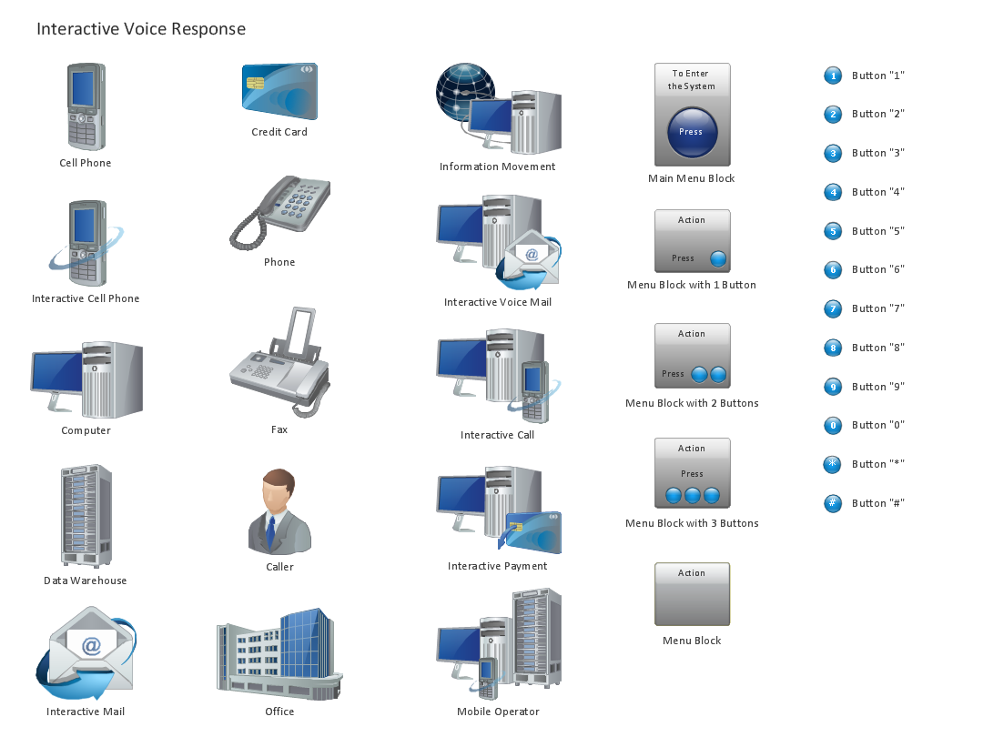
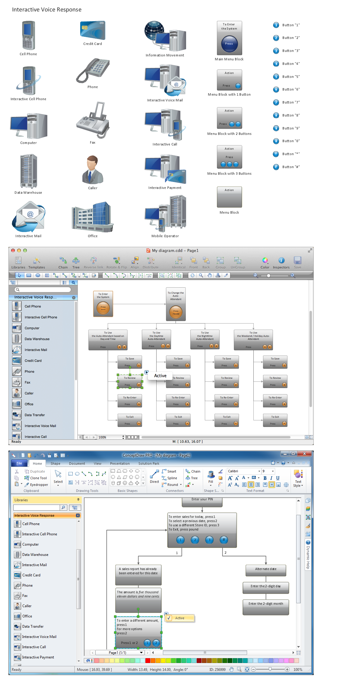
Interactive Voice Response Diagrams solution extends ConceptDraw DIAGRAM software with samples, templates and libraries of ready-to-use vector stencils that help create Interactive Voice Response (IVR) diagrams illustrating in details a work of interactive voice response system, the IVR system’s logical and physical structure, Voice-over-Internet Protocol (VoIP) diagrams, and Action VoIP diagrams with representing voice actions on them, to visualize how the computers interact with callers through voice recognition and dual-tone multi-frequency signaling (DTMF) keypad inputs.
The vector stencils library "Cisco network topology" contains 89 symbols of Cisco network devices and design elements for drawing computer network topology diagrams using the ConceptDraw PRO diagramming and vector drawing software.
"Network topology is an arrangement of the various elements (links, nodes, etc.) of a computer network. Essentially, it is the topological structure of a network, and may be depicted physically or logically. Physical topology refers to the placement of the network's various components, including device location and cable installation, while logical topology shows how data flows within a network, regardless of its physical design. Distances between nodes, physical interconnections, transmission rates, and/ or signal types may differ between two networks, yet their topologies may be identical.
A good example is a local area network (LAN): Any given node in the LAN has one or more physical links to other devices in the network; graphically mapping these links results in a geometric shape that can be used to describe the physical topology of the network. Conversely, mapping the data flow between the components determines the logical topology of the network." [Network topology. Wikipedia]
The example "Design elements - Cisco network topology" is included in the Cisco Network Diagrams solution from the Computer and Networks area of ConceptDraw Solution Park.
Cisco network topology symbols

Control and Information Architecture Diagrams (CIAD) with ConceptDraw DIAGRAM
Applications

- Design Element : IVR for Network Diagrams | Network Diagramming ...
- How to Draw a Computer Network Diagrams | Design Element : IVR ...
- Network Diagram Software Logical Network Diagram | Network ...
- Network Diagram Software Logical Network Diagram | Network ...
- Network Architecture | Network diagrams with ConceptDraw PRO ...
- Network Diagramming Software for Design Network Layout Diagrams
- Network diagrams with ConceptDraw PRO | Interactive Voice ...
- Best Vector Drawing Application for Mac OS X | Design Element ...
- Logical network diagram
- Design Element : IVR for Network Diagrams | Network Diagramming
- Design Element : IVR for Network Diagrams | Network Diagramming ...
- IVR for Network Diagrams
- How to Draw a Computer Network Diagrams | Network Diagram ...
- Hotel Network Topology Diagram | Logical network topology ...
- How to Draw a Computer Network Diagrams | Computer network ...
- Computer network system design diagram | How to Draw a ...
- Sales Dashboard - Access Anywhere | Design elements ...
- UML Composite Structure Diagram | Network Architecture | Network ...
- How to Draw a Computer Network Diagrams | Computer network ...
- Network Printer | Computer network diagram | Logical network ...