 Entity-Relationship Diagram (ERD)
Entity-Relationship Diagram (ERD) solution extends ConceptDraw DIAGRAM software with templates, samples and libraries of vector stencils from drawing the ER-diagrams by Chen's and crow’s foot notations.
Applications
ConceptDraw DIAGRAM is a multipurpose software from ConceptDraw suite intended for diagramming, business and technical drawing, and visual documenting. You can reach a lot of practical benefits from the use of ConceptDraw DIAGRAM. The list of ConceptDraw DIAGRAM applications and versatile possibilities is extremely great. Among them network and system diagramming, business diagramming, Cisco network design, network visualization, software and database design, software development, business flowcharting, data flow design, databases modeling and visualization, business processes modeling, business drawing, technical drawing, GUI prototyping, Organizational charts construction, business processes fixing, web site planning and design, Internet solutions design, information architecture design, UML modeling, ER diagrams design, home and landscape design, and a lot of other applications. ConceptDraw DIAGRAM offers the users a beneficial collaboration, compatibility with MS Visio and many other popular programs, including other products from ConceptDraw suite."Interrelationship Digraph (ID).
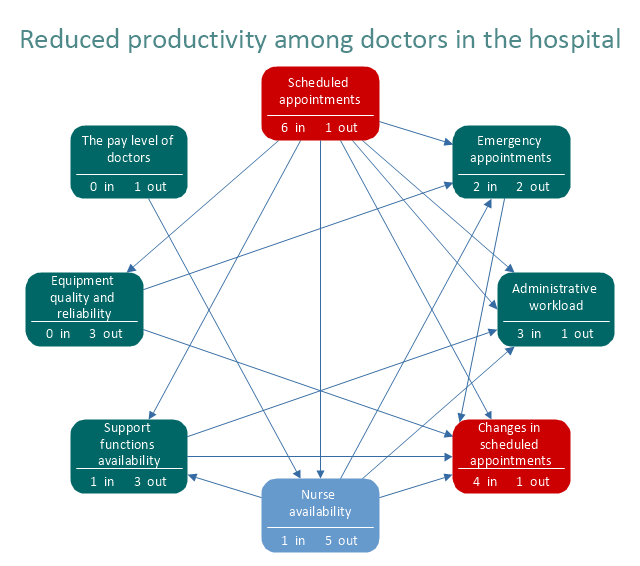
This tool displays all the interrelated cause-and-effect relationships and factors involved in a complex problem and describes desired outcomes. The process of creating an interrelationship digraph helps a group analyze the natural links between different aspects of a complex situation." [Seven Management and Planning Tools. Wikipedia]
"Causality (also referred to as causation) is the relation between an event (the cause) and a second event (the effect), where the second event is understood as a consequence of the first.
In common usage, causality is also the relation between a set of factors (causes) and a phenomenon (the effect). Anything that affects an effect is a factor of that effect. A direct factor is a factor that affects an effect directly, that is, without any intervening factors. (Intervening factors are sometimes called "intermediate factors".) The connection between a cause(s) and an effect in this way can also be referred to as a causal nexus.
Though the causes and effects are typically related to changes or events, candidates include objects, processes, properties, variables, facts, and states of affairs; characterizing the causal relation can be the subject of much debate." [Causality. Wikipedia]
The relations diagram example "Health care" was created using the ConceptDraw PRO diagramming and vector drawing software extended with the solution "Seven Management and Planning Tools" from the Management area of ConceptDraw Solution Park.
 Wireless Networks
The Wireless Networks Solution extends ConceptDraw DIAGRAM software with professional diagramming tools, set of wireless network diagram templates and samples, comprehensive library of wireless communications and WLAN objects to help network engineers and designers efficiently design and create Wireless network diagrams that illustrate wireless networks of any speed and complexity, and help to identify all required equipment for construction and updating wireless networks, and calculating their costs.
- Fishbone Diagram | Entity-Relationship Diagram ( ERD ) | Business ...
- Entity-Relationship Diagram ( ERD ) | PROBLEM ANALYSIS Root ...
- ER Diagrams with ConceptDraw PRO | Entity-Relationship Diagram ...
- ERD Symbols and Meanings | Entity Relationship Diagram Symbols ...
- How to Create Cisco Network Diagram - Conceptdraw.com
- Entity-Relationship Diagram ( ERD ) | Basic Flowchart Symbols | How ...
- Entity Relationship Diagram Symbols | Graphical Symbols to use in ...
- Universal Diagramming Area | Entity Relationship Diagram Software ...
- Entity Relationship Diagram Symbols | ERD Symbols and Meanings ...
- Fishbone Diagram | Business Productivity Diagramming | Entity ...
- UML Diagram Visio | Cross-Functional Flowchart | Entity ...
- UML Notation | Business Process Modeling with ConceptDraw ...
- ERD Symbols and Meanings | Entity Relationship Diagram Symbols ...
- Event-driven Process Chain Diagrams EPC | Process Flowchart ...
- ER Diagrams with ConceptDraw PRO | Entity-Relationship Diagram ...
- Entity-Relationship Diagram ( ERD ) | Event-driven Process Chain ...
- Entity Relationship Diagram Software Engineering | Universal ...
- Entity-Relationship Diagram ( ERD ) | Pyramid Diagrams | Types of ...
- Drawing ER diagrams or on a Mac
- Diagramming Software for Design UML Activity Diagrams | Entity ...

