DFD Library System

Diagramming Software for Design UML Use Case Diagrams


Jacobson Use Cases Diagram

ATM Solutions
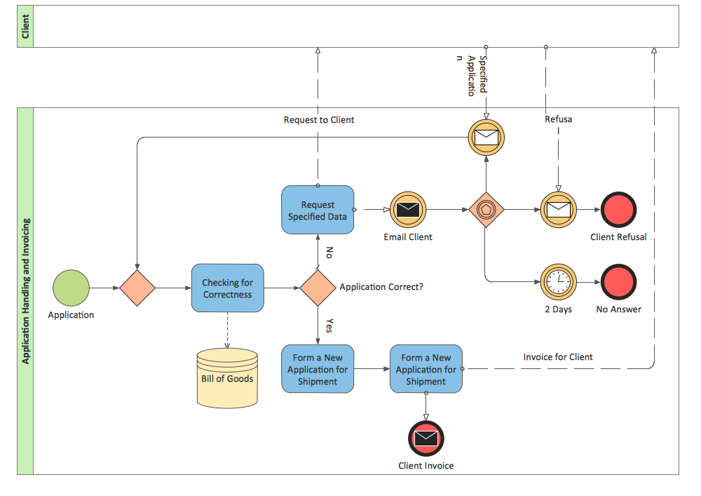
BPMN 2.0
UML Deployment Diagram. Design Elements

UML Use Case Diagram Example. Social Networking Sites Project

Yourdon and Coad Diagram

Bank Sequence Diagram

UML Deployment Diagram
Banking System

UML Diagrams with ConceptDraw DIAGRAM

Model Based Systems Engineering

Bank UML Diagram

Use Case Diagrams technology with ConceptDraw DIAGRAM

- Er Diagram For A Banking Transaction System
- UML Use Case Diagram Example. Services UML Diagram. ATM ...
- Data Flow Diagrams (DFD) | Entity-Relationship Diagram ( ERD ...
- Bank Transaction Relationship Diagram
- Entity-Relationship Diagram ( ERD ) | UML Use Case Diagram ...
- Entity-Relationship Diagram ( ERD ) | ATM UML Diagrams | ATM ...
- Er Diagram For Bank Transaction System
- ATM Solutions | UML Use Case Diagram Example. Services UML ...
- UML Deployment Diagram Example - ATM System UML diagrams ...
- UML Use Case Diagram Example. Services UML Diagram. ATM ...
- ATM Solutions | ConceptDraw PRO ER Diagram Tool | DFD Library ...
- ATM Solutions | Entity-Relationship Diagram ( ERD ) | Entity ...
- ATM Solutions | Data Flow Diagrams (DFD) | DFD Library System ...
- DFD Library System | Account Flowchart Stockbridge System ...
- UML Use Case Diagram Example. Services UML Diagram. ATM ...
- Er Diagram For Atm Banking System
- Credit Card Management System Erd
- Use Case And Er Diagrams For Online Bank Management System
- Component And Deployment Diagram For Library Management
- Use Case Diagram For Library Management System Visio