HelpDesk
How to Create a Fault Tree Analysis Diagram (FTD) in ConceptDraw PRO
Fault Tree Diagram are logic diagram that shows the state of an entire system in a relationship of the conditions of its elements. Fault Tree Diagram are used to analyze the probability of functional system failures and safety accidents. ConceptDraw PRO allows you to create professional Fault Tree Diagrams using the basic FTD symbols. An FTD visualize a model of the processes within a system that can lead to the unlikely event. A fault tree diagrams are created using standard logic symbols . The basic elements in a fault tree diagram are gates and events.
 Sport Field Plans
Construction of sport complex, playgrounds, sport school, sport grounds and fields assumes creation clear plans, layouts, or sketches. In many cases you need represent on the plan multitude of details, including dimensions, placement of bleachers, lighting, considering important sport aspects and other special things.
"A commercial building is a building that is used for commercial use. Types can include office buildings, warehouses, or retail (i.e. convenience stores, 'big box' stores, shopping malls, etc.). In urban locations, a commercial building often combines functions, such as an office on levels 2-10, with retail on floor 1. Local authorities commonly maintain strict regulations on commercial zoning, and have the authority to designate any zoned area as such. A business must be located in a commercial area or area zoned at least partially for commerce." [Commercial building. Wikipedia]
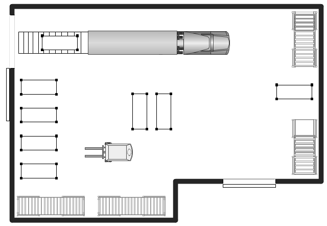
The warehouse floor plan example "Shipping, receiving and storage" was created using the ConceptDraw PRO diagramming and vector drawing software extended with the Plant Layout Plans solution from the Building Plans area of ConceptDraw Solution Park.
The warehouse floor plan example "Shipping, receiving and storage" was created using the ConceptDraw PRO diagramming and vector drawing software extended with the Plant Layout Plans solution from the Building Plans area of ConceptDraw Solution Park.
 Electrical Engineering
This solution extends ConceptDraw PRO v.9.5 (or later) with electrical engineering samples, electrical schematic symbols, electrical diagram symbols, templates and libraries of design elements, to help you design electrical schematics, digital and analog
ConceptDraw PRO
ConceptDraw PRO is a powerful business and technical diagramming software tool that enables you to design professional-looking graphics, diagrams, flowcharts, floor plans and much more in just minutes. Maintain business processes performance with clear visual documentation. Effectively present and communicate information in a clear and concise manner with ConceptDraw PRO.- Floor Plan Gate Symbol
- 2-bit ALU - Logic gate diagram | Computers - Vector stencils library ...
- Sign Of Main Gate In Site Plan
- Floor Plan Of A Gate And Security House
- Access and security - Vector stencils library | Access and security ...
- Whats The Symbol For Gate On A Site Plan
- Health club floor plan | Site accessories - Vector stencils library ...
- Security Gate
- Doors Vector Plan
- Electrical Engineering | Electrical Symbol For Safety Gate
- Site Plan Drawing Symbols Gate
- Interior Design Site Plan - Design Elements | Interior Design Piping ...
- Security and Access Plans | How to Draw a Security and Access ...
- Straight Double Gate Plans Diagram
- How Represent Gate On Plan
- Circuits and Logic Diagram Software | Electric and Telecom Plans ...
- How To use Appliances Symbols for Building Plan | Interior Design ...
- Site Plans | Building Drawing Design Element Site Plan | Design ...
- Electrical Gate Symbols
- How to Draw a Security and Access Floor Plan | Design elements ...


