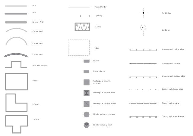
The vector stencils library "Walls, shell and structure" contains 29 shapes of walls, windows, doors, pillars. Use it for drawing architectural blueprints, home and building design, space plans, and construction and house framing diagrams in the ConceptDraw PRO diagramming and vector drawing software extended with the Floor Plans solution from the Building Plans area of ConceptDraw Solution Park.
The vector stencils library "Walls, shell and structure" contains 29 shapes of walls, windows, doors, pillars. Use it for drawing architectural blueprints, home and building design, space plans, and construction and house framing diagrams in the ConceptDraw PRO diagramming and vector drawing software extended with the Floor Plans solution from the Building Plans area of ConceptDraw Solution Park.
The vector stencils library "Walls, shell and structure" contains 29 shapes of walls, windows, doors, pillars. Use it for drawing architectural blueprints, home and building design, space plans, and construction and house framing diagrams in the ConceptDraw PRO diagramming and vector drawing software extended with the Floor Plans solution from the Building Plans area of ConceptDraw Solution Park.
The vector stencils library "Walls, shell and structure" contains 29 shapes of walls, windows, doors, pillars. Use it for drawing architectural blueprints, home and building design, space plans, and construction and house framing diagrams in the ConceptDraw PRO diagramming and vector drawing software extended with the Floor Plans solution from the Building Plans area of ConceptDraw Solution Park.
The vector stencils library "Walls, shell and structure" contains 29 shapes of walls, windows, doors, pillars. Use it for drawing architectural blueprints, home and building design, space plans, and construction and house framing diagrams in the ConceptDraw PRO diagramming and vector drawing software extended with the Floor Plans solution from the Building Plans area of ConceptDraw Solution Park.
The vector stencils library "Rack diagrams" contains 33 rack design elements for drawing the computer network server rack diagrams.
"A 19-inch rack is a standardized frame or enclosure for mounting multiple equipment modules. Each module has a front panel that is 19 inches (482.6 mm) wide, including edges or ears that protrude on each side which allow the module to be fastened to the rack frame with screws. ...
Equipment designed to be placed in a rack is typically described as rack-mount, rack-mount instrument, a rack mounted system, a rack mount chassis, subrack, rack mountable, or occasionally simply shelf. The height of the electronic modules is also standardized as multiples of 1.75 inches (44.45 mm) or one rack unit or U (less commonly RU). The industry standard rack cabinet is 42U tall. ...
19-inch racks in 2-post or 4-post form hold most equipment in modern data centers, ISP facilities and professionally designed corporate server rooms. They allow for dense hardware configurations without occupying excessive floorspace or requiring shelving." [19-inch rack. Wikipedia]
The clip art example "Rack diagrams - Vector stencils library" was created using the ConceptDraw PRO diagramming and vector drawing software extended with the Rack Diagrams solution from the Computer and Networks area of ConceptDraw Solution Park.
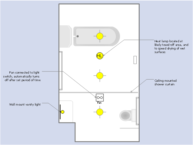
This RCP sample was drawn on the base of the prototype bathroom plan from the website of the Oregon Department of Human Services (DHS), USA.
[oregon.gov/ dhs/ spd/ pages/ provtools/ dd/ safety_ design/ bath.aspx]
"A bathroom is a room for personal hygiene, generally containing a bathtub or a shower, and possibly also a bidet. In North America and some other regions, it characteristically contains a toilet and a sink; hence in North American English the word "bathroom" is commonly used to mean any room containing a toilet, even a public toilet (although in the United States this is more commonly called a restroom). In other countries, including the UK, Australia, France and Japan, homes may have a separate toilet. In Iran almost all homes have two distinct rooms for bathroom and toilet room." [Bathroom. Wikipedia]
The reflected ceiling plan example "RCP - Prototype bathroom design" was created using the ConceptDraw PRO diagramming and vector drawing software extended with the Reflected Ceiling Plans solution from the Building Plans area of ConceptDraw Solution Park.
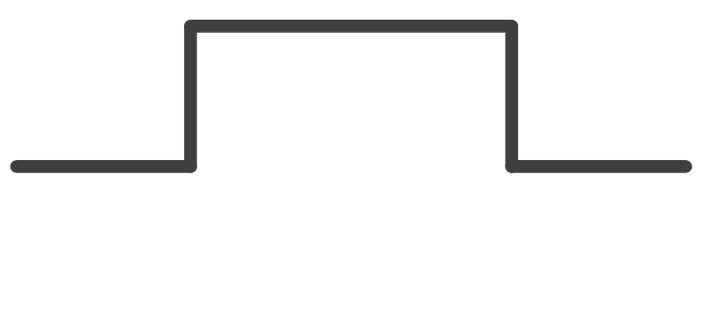
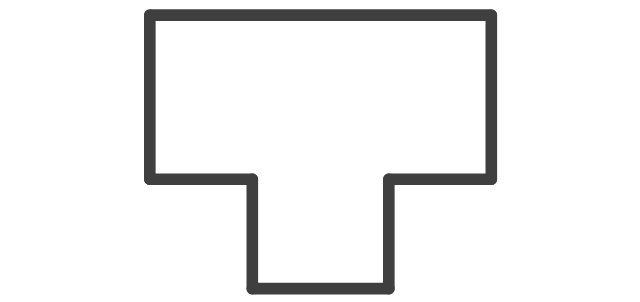
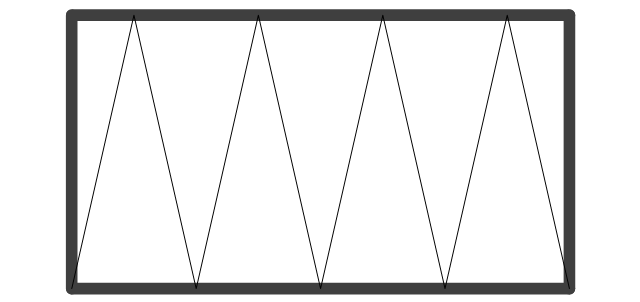
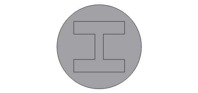
The design elements library Walls, shell and structure contains 29 symbols of structural elements: walls, rooms, windows, doors, pillars.
Use the vector stencils library Walls, shell and structure to draw the floor plans and other architectural drawings, blueprints, home and building interior design, space layout plans, construction and house framing diagrams using the ConceptDraw PRO diagramming and vector drawing software.
"A wall is a horizontal structure, usually solid, that defines and sometimes protects an area. Most commonly, a wall delineates a building and supports its superstructure, separates space in buildings into sections, or protects or delineates a space in the open air. There are three principal types of structural walls: building walls, exterior boundary walls, and retaining walls.
Building walls have one main purpose: to support roofs and ceilings. Such walls most often have three or more separate components. In today's construction, a building wall will usually have the structural elements (such as 2×4 studs in a house wall), insulation, and finish elements or surface (such as drywall or panelling). In addition, the wall may house various types of electrical wiring or plumbing. Electrical outlets are usually mounted in walls.
Building walls frequently become works of art externally and internally, such as when featuring mosaic work or when murals are painted on them; or as design foci when they exhibit textures or painted finishes for effect.
In architecture and civil engineering, the term curtain wall refers to the facade of a building which is not load-bearing but functions as decoration, finish, front, face, or history preservation." [Wall. Wikipedia]
This shapes library Walls, shell and structure is provided by the Floor Plans solution from the Building Plans area of ConceptDraw Solution Park.
This reflected ceiling plan sample was created on the base of the article "How to Read a Reflected Ceiling Plan" from wikiHow.com.
"A reflected ceiling plan (RCP) is a drawing, which shows the items that are located on the ceiling of a room or space. It is referred to as a reflected ceiling plan since it is drawn to display a view of the ceiling as if it was reflected onto a mirror on the floor. This way the reflected ceiling plan has the same orientation as the floor plan associated with it. It is as if the ceiling was see-through and you could see right through it to the floor below. Architects and interior designers draw reflected ceiling plans when designing spaces." [wikihow.com/ Read-a-Reflected-Ceiling-Plan]
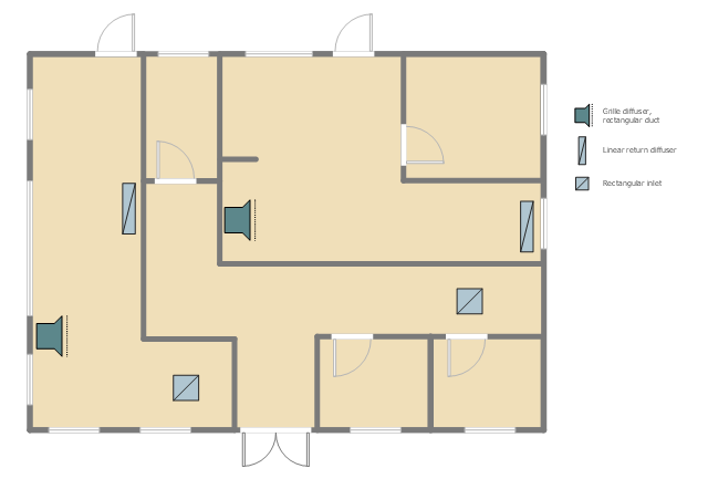
The HVAC layout example "RCP- HVAC layout" was created using the ConceptDraw PRO diagramming and vector drawing software extended with the Reflected Ceiling Plans solution from the Building Plans area of ConceptDraw Solution Park.
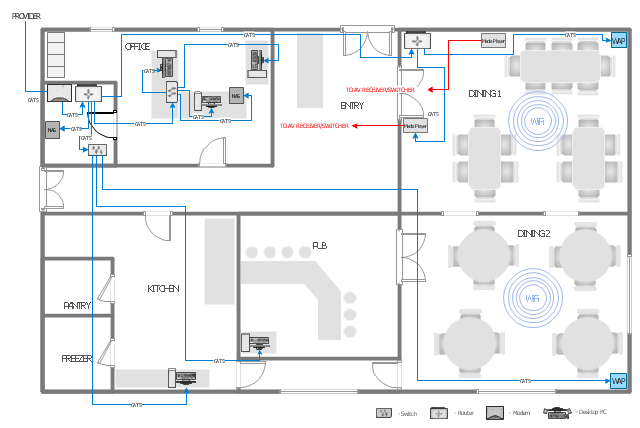
This computer network layout floorplan was drawn on the base of the picture from the Media Institute blog of the Madison Media Institute.
[mediainstitute.edu/ media-schools-blog/ wp-content/ uploads/ 2012/ 01/ floor_ plan.png]
The example "Restaurant network layout floorplan" was created using the ConceptDraw PRO diagramming and vector drawing software extended with the Network Layout Floor Plans solution from the Computer and Networks area of ConceptDraw Solution Park.
 Stakeholder Onion Diagrams
The Stakeholder Onion Diagram is often used as a way to view the relationships of stakeholders to a project goal. A basic Onion Diagram contains a rich information. It shows significance of stakeholders that will have has influence to the success achieve
 Chemical and Process Engineering
This chemical engineering solution extends ConceptDraw PRO v.9.5 (or later) with process flow diagram symbols, samples, process diagrams templates and libraries of design elements for creating process and instrumentation diagrams, block flow diagrams (BFD
 Website Wireframe
The innovative Website Wireframe solution enhances the ConceptDraw PRO v10 functionality with newest wireframe tools, libraries with variety of predesigned icons, symbols, buttons, graphics, forms, boxes, and many other vector elements, templates and professionally designed samples, which make it the best wireframing software. Website Wireframe solution gives you significant advantages when designing and maintaining websites, creating skeletal and content-free depictions of website structure, making website prototypes and planning the content arrangement before committing to design, also speeds up the processes of sketching, producing and sharing wireframe examples of website style and interface design.
 Australia Map
For graphic artists creating accurate maps of Australia. The Australia Map solution - allows designers to map Australia for their needs, offers a collection of scalable graphics representing the political geography of Australia, split into distinct state
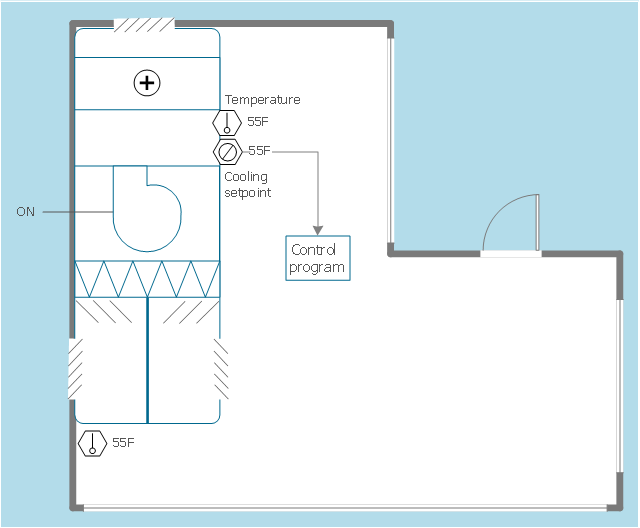
This HVAC floor plan sample illustrates the temperature sensors of air handler digital thermostat control.
"A thermostat is a component of a control system which senses the temperature of a system so that the system's temperature is maintained near a desired setpoint. The thermostat does this by switching heating or cooling devices on or off, or regulating the flow of a heat transfer fluid as needed, to maintain the correct temperature. The name is derived from the Greek words thermos "hot" and statos "a standing".
A thermostat may be a control unit for a heating or cooling system or a component part of a heater or air conditioner. Thermostats can be constructed in many ways and may use a variety of sensors to measure the temperature. The output of the sensor then controls the heating or cooling apparatus. A thermostat may switch on and off at temperatures either side of the setpoint the extent of the difference is known as hysteresis and prevents too frequent switching of the controlled equipment." [Thermostat. Wikipedia]
The HVAC plan example "Digital unit ventilator control" was created using the ConceptDraw PRO diagramming and vector drawing software extended with the HVAC Plans solution from the Building Plans area of ConceptDraw Solution Park.
 Collaboration Area
The solutions from Collaboration area of ConceptDraw Solution Park extend ConceptDraw PRO and ConceptDraw MINDMAP software with features, samples, templates and vector stencils libraries for drawing diagrams and mindmaps useful for collaboration.
 eLearning for Skype
This solution extends ConceptDraw MINDMAP software with the ability to prepare and run remote learning sessions by using Skype
- L - Room
- Design elements - Walls, shell and structure | Walls, shell and ...
- Room Divider
- Venn Diagram Examples for Problem Solving. Environmental Social ...
- T- Room
- Digital unit ventilator control - HVAC plan | Classroom and computer ...
- Room planning with ConceptDraw PRO | Room Planning Software ...
- Blow-through unit ventilator - HVAC plan | Bacteria Drawing
- Shipping, receiving and storage | Retail Store Layout Plan
- Walls, shell and structure - Vector stencils library
- Doors - Vector stencils library | Design elements - Doors and ...
- Building Drawing Design Element: Plumbing | Interior Design Piping ...
- Restaurant plan | Classroom floor plan | Office plan - Cubicle layout ...
- Building Drawing Software for Designing Plumbing | Interior Design ...
- HVAC Plans | Design elements - HVAC control equipment | Design ...
- Design elements - HVAC controls | Business Process Elements ...
- Rack diagrams - Vector stencils library | Floor Plans | Gym and Spa ...
- Rack diagrams - Vector stencils library | Application server rack ...
- Camera layout schematic | Design elements - Video | CCTV Network ...
- Café Floor Plan Example | Building Plan Software. Building Plan ...













-rack-diagrams---vector-stencils-library.png--diagram-flowchart-example.png)


-rack-diagrams---vector-stencils-library.png--diagram-flowchart-example.png)
-rack-diagrams---vector-stencils-library.png--diagram-flowchart-example.png)
-rack-diagrams---vector-stencils-library.png--diagram-flowchart-example.png)
-rack-diagrams---vector-stencils-library.png--diagram-flowchart-example.png)
-rack-diagrams---vector-stencils-library.png--diagram-flowchart-example.png)
-rack-diagrams---vector-stencils-library.png--diagram-flowchart-example.png)


-rack-diagrams---vector-stencils-library.png--diagram-flowchart-example.png)
-rack-diagrams---vector-stencils-library.png--diagram-flowchart-example.png)
-rack-diagrams---vector-stencils-library.png--diagram-flowchart-example.png)


