HelpDesk
How to Create a Mechanical Diagram
Mechanical Engineering drawing is a type of technical drawing that helps analyze complex engineering systems. Mechanical Engineering diagrams are often a set of detailed drawings used for engineering or construction projects.Making Mechanical Engineering diagram involves many different elements that can be managed using ConceptDraw PRO. You can design elements for drawing parts, assembly, pneumatic, and hydraulic systems for mechanical engineering. With ConceptDraw PRO you can easily create and communicate the Mechanical Engineering diagram of any complexity.
 ConceptDraw Solution Park
ConceptDraw Solution Park collects graphic extensions, examples and learning materials
HelpDesk
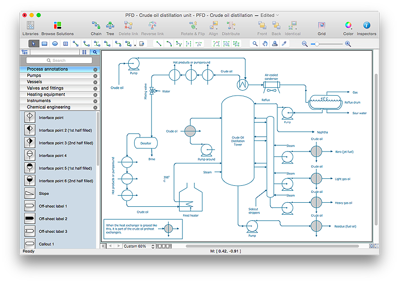
How to Draw a Chemical Process Flow Diagram
Process Flow Diagram widely used in modeling of processes in the chemical industry. A Chemical Process Flow diagram (PFD) is a specialized type of flowchart. With the help of Chemical Process Flow Diagram engineers can easily specify the general scheme of the processes and chemical plant equipment. Chemical Process Flow Diagram displays the real scheme of the chemical process, the relationship between the equipment and the technical characteristics of the process. Chemical Process Flow Diagram illustrates the connections between the basic equipment as well as the overall structure of pipelines and other supporting equipment. The purpose of the PFD is to build the image of the basic idea of the chemical process. ConceptDraw PRO together with its Chemical and Process Engineering solution delivers the possibility to design Chemical Process Flow diagrams. It is designed for chemical industry engineers and designers.
 Floor Plans
Construction, repair and remodeling of the home, flat, office, or any other building or premise begins with the development of detailed building plan and floor plans. Correct and quick visualization of the building ideas is important for further construction of any building.
- Basic Flowchart Symbols | Flow Chart Symbols | Process Flowchart ...
- Hydraulic circuits | Design elements - Hydraulic pumps and motors ...
- UML Notation | Design elements - Bearings | UML Class Diagram ...
- Computer Networking Tools List | ConceptDraw Solution Park ...
- Data Flow Diagram Symbols . DFD Library | Entity Relationship ...
- ConceptDraw Solution Park | Mechanical Engineering | Design ...
- Draw Five Symbols Used In Flow Chart
- Azure Architecture | How to Create an Azure Architecture Diagram ...
- Mechanical Engineering | How to Create a Mechanical Diagram ...
- Electrical Drawing Software | How To use House Electrical Plan ...
- Mechanical Drawing Symbols And Meanings
- Drawing Symbol Used In Industry
- Designing Drawing Symbol
- Mechanical Engineering Drawing Machining Symbols
- Technical Drawing Moving Parts
- Common joint types | Polygon types | Bubble diagrams in ...
- Mechanical Drawing Symbols | Mechanical Drawing Software ...
- Computer Networking Tools List | How to Determine what ...
- Assembly And Symbols Used In Machine Design
- Flow Process Chart Equipment Type

