"The Ethernet physical layer is the physical layer component of the Ethernet family of computer network standards.
The Ethernet physical layer evolved over a considerable time span and encompasses quite a few physical media interfaces and several magnitudes of speed. The speed ranges from 1 Mbit/ s to 100 Gbit/ s, while the physical medium can range from bulky coaxial cable to twisted pair and optical fiber. In general, network protocol stack software will work similarly on all physical layers.
10-gigabit Ethernet was already used in both enterprise and carrier networks by 2007, with 40 Gbit/ s and 100 Gbit/ s Ethernet ratified. ...
Many Ethernet adapters and switch ports support multiple speeds, using autonegotiation to set the speed and duplex for the best values supported by both connected devices. If auto-negotiation fails, a multiple-speed device will sense the speed used by its partner, but will assume half-duplex. A 10/ 100 Ethernet port supports 10BASE-T and 100BASE-TX. A 10/ 100/ 1000 Ethernet port supports 10BASE-T, 100BASE-TX, and 1000BASE-T." [Ethernet physical layer. Wikipedia]
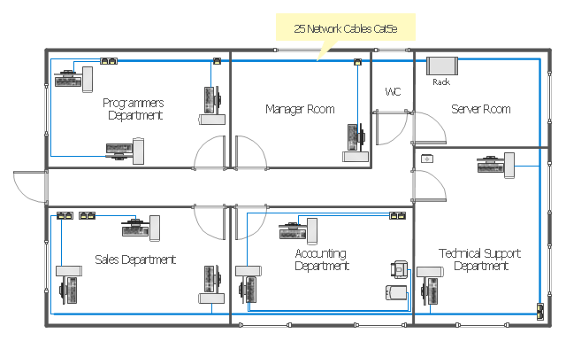
The LAN equipment and cabling layout floorplan example "Ethernet local area network layout floor plan" was created using the ConceptDraw PRO diagramming and vector drawing software extended with the Network Layout Floor Plans solution from the Computer and Networks area of ConceptDraw Solution Park.
HelpDesk
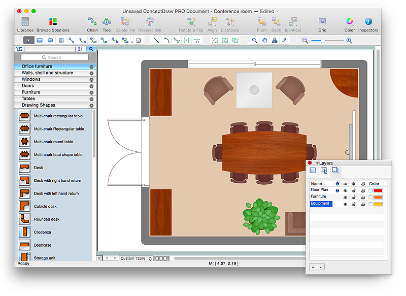
How to Draw a Floor Plan for Your Office
Designing the right office space is is an essential factor of business productivity. An office floor plan should reflect the needs of both employees and customers. ConceptDraw PRO allows you to draw the Floor Plan for your office using a special office equipment library as well as set of special objects that displays the sizes, corners, squares and other floor plan details.
 Network Layout Floor Plans
Network Layout Floor Plans solution extends ConceptDraw PRO software functionality with powerful tools for quick and efficient documentation the network equipment and displaying its location on the professionally designed Network Layout Floor Plans. Never before creation of Network Layout Floor Plans, Network Communication Plans, Network Topologies Plans and Network Topology Maps was not so easy, convenient and fast as with predesigned templates, samples, examples and comprehensive set of vector design elements included to the Network Layout Floor Plans solution. All listed types of plans will be a good support for the future correct cabling and installation of network equipment.
"A smoke detector is a device that detects smoke, typically as an indicator of fire. Commercial, industrial, and mass residential devices issue a signal to a fire alarm system, while household detectors, known as smoke alarms, generally issue a local audible or visual alarm from the detector itself.
Most smoke detectors work either by optical detection (photoelectric) or by physical process (ionization), while others use both detection methods to increase sensitivity to smoke." [Smoke detector. Wikipedia]
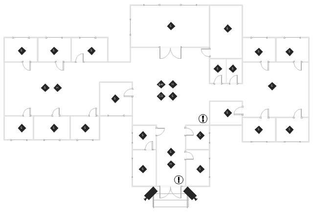
This smoke alarm equipment layout floor plan example was created using the ConceptDraw PRO diagramming and vector drawing software extended with the Security and Access Plans solution from the Building Plans area of ConceptDraw Solution Park.
"A commercial building is a building that is used for commercial use. Types can include office buildings, warehouses, or retail (i.e. convenience stores, 'big box' stores, shopping malls, etc.). In urban locations, a commercial building often combines functions, such as an office on levels 2-10, with retail on floor 1. Local authorities commonly maintain strict regulations on commercial zoning, and have the authority to designate any zoned area as such. A business must be located in a commercial area or area zoned at least partially for commerce." [Commercial building. Wikipedia]
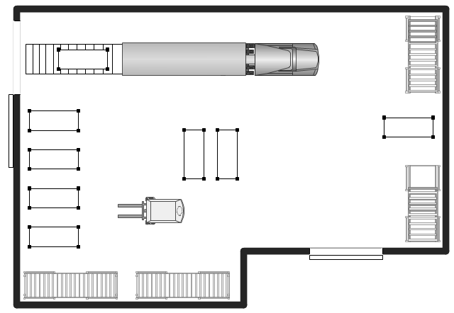
The warehouse floor plan example "Shipping, receiving and storage" was created using the ConceptDraw PRO diagramming and vector drawing software extended with the Plant Layout Plans solution from the Building Plans area of ConceptDraw Solution Park.
The warehouse floor plan example "Shipping, receiving and storage" was created using the ConceptDraw PRO diagramming and vector drawing software extended with the Plant Layout Plans solution from the Building Plans area of ConceptDraw Solution Park.
 Cisco Network Diagrams
Cisco Network Diagrams solution extends ConceptDraw PRO with the best characteristics of network diagramming software. Included samples, templates and libraries of built-in standardized vector Cisco network icons and Cisco symbols of computers, network devices, network appliances and other Cisco network equipment will help network engineers, network designers, network and system administrators, as well as other IT professionals and corporate IT departments to diagram efficiently the network infrastructure, to visualize computer networks topologies, to design Cisco computer networks, and to create professional-looking Cisco Computer network diagrams, Cisco network designs and schematics, Network maps, and Network topology diagrams in minutes.
 Australia Map
For graphic artists creating accurate maps of Australia. The Australia Map solution - allows designers to map Australia for their needs, offers a collection of scalable graphics representing the political geography of Australia, split into distinct state
 Vehicular Networking
Network engineering is an extensive area with wide range of applications. Depending to the field of application, network engineers design and realize small networks or complex networks, which cover wide territories. In latter case will be ideal recourse to specialized drawing software, such as ConceptDraw PRO.
The vector stenvils library "Outlets" contains 57 symbols of electrical outlets.
Use these shapes for drawing building interior design, electrical floor plans and layouts of AC power plugs and sockets in the ConceptDraw PRO diagramming and vector drawing software.
The vector stencils library "Outlets" is included in the Electric and Telecom Plans solution from the Building Plans area of ConceptDraw Solution Park.
- Network Layout Floor Plans | Network Layout | Design elements ...
- Network Layout Floor Plans | Ethernet local area network layout floor ...
- Ethernet local area network layout floor plan | Local network ...
- Network Layout Floor Plans | Cafe and Restaurant Floor Plan ...
- Network Layout Floor Plans | | | Network Cable Layout Plan
- Ethernet local area network layout floor plan | Network Layout Floor ...
- Network Layout Floor Plans | Network Layout | Ethernet local area ...
- Ethernet local area network layout floor plan | Gym and Spa Area ...
- Network Layout Floor Plans | Local area network (LAN). Computer ...
- Ethernet local area network layout floor plan | Network layout ...
- Network Layout Floor Plans | Logical network topology diagram ...
- Network Layout Floor Plans | Computer and Networks Area | Local ...
- Tree Network Topology Diagram | Network Layout Floor Plans ...
- Ethernet local area network layout floor plan | Network Diagram ...
- Activity Network Diagram Method | Network Layout Floor Plans ...
- Floor Plan Layout And Network Cabling
- Network Layout Floor Plans | Network Layout | Local area network ...
- Network Layout Floor Plans | Design elements - Network layout ...
- Network Layout Floor Plans | Local network area. Computer and ...
- Network Layout Floor Plans | Illustrate A Simple Local Area Network
