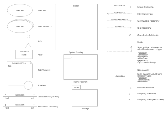
The vector stencils library "UML use case diagrams" contains 25 symbols for the ConceptDraw PRO diagramming and vector drawing software.
"Use case diagrams are usually referred to as behavior diagrams used to describe a set of actions (use cases) that some system or systems (subject) should or can perform in collaboration with one or more external users of the system (actors). Each use case should provide some observable and valuable result to the actors or other stakeholders of the system. ...
Use case diagrams are in fact twofold - they are both behavior diagrams, because they describe behavior of the system, and they are also structure diagrams - as a special case of class diagrams where classifiers are restricted to be either actors or use cases related to each other with associations. ...
Use case is usually shown as an ellipse containing the name of the use case. ...
Name of the use case could also be placed below the ellipse. ...
If a subject (or system boundary) is displayed, the use case ellipse is visually located inside the system boundary rectangle. Note, that this does not necessarily mean that the subject classifier owns the contained use cases, but merely that the use case applies to that classifier. ...
A list of use case properties - operations and attributes - could be shown in a compartment within the use case oval below the use case name. ...
Use case with extension points may be listed in a compartment of the use case with the heading extension points. ...
A use case can also be shown using the standard rectangle notation for classifiers with an ellipse icon in the upper right-hand corner of the rectangle and with optional separate list compartments for its features. ...
Subject (sometimes called a system boundary) is presented by a rectangle with subject's name, associated keywords and stereotypes in the upper left corner. Use cases applicable to the subject are located inside the rectangle and actors - outside of the system boundary. ...
Standard UML notation for actor is "stick man" icon with the name of the actor above or below of the icon. Actor names should follow the capitalization and punctuation guidelines for classes. The names of abstract actors should be shown in italics. ...
Custom icons that convey the kind of actor may also be used to denote an actor, such as using a separate icon(s) for non-human actors. ...
An actor may also be shown as a class rectangle with the standard keyword «actor», having usual notation for class compartments ...
An actor can only have binary associations to use cases, components, and classes. ...
An association between an actor and a use case indicates that the actor and the use case somehow interact or communicate with each other.
Only binary associations are allowed between actors and use cases.
An actor could be associated to one or several use cases. ...
A use case may have one or several associated actors." [uml-diagrams.org/ use-case-diagrams.html]
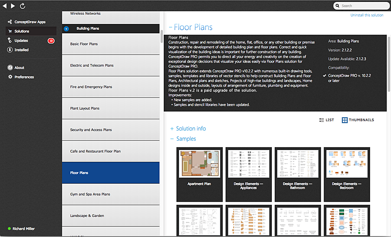
The example "Design elements - UML use case diagrams" is included in the Rapid UML solution from the Software Development area of ConceptDraw Solution Park.
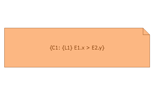
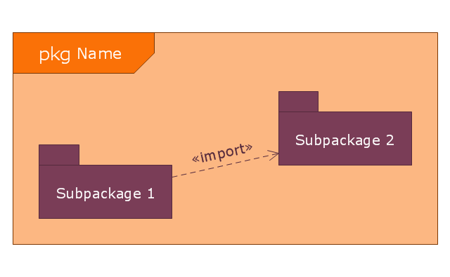
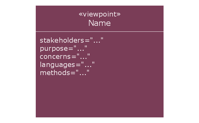
This vector stencils library contains 19 SysML symbols.
Use it to design your SysML diagrams using ConceptDraw PRO diagramming and vector drawing software.
"The Systems Modeling Language (SysML) is a general-purpose modeling language for systems engineering applications. It supports the specification, analysis, design, verification and validation of a broad range of systems and systems-of-systems.
SysML was originally developed by an open source specification project, and includes an open source license for distribution and use. SysML is defined as an extension of a subset of the Unified Modeling Language (UML) using UML's profile mechanism." [Systems Modeling Language. Wikipedia]
The vector stencils library "SysML diagrams" is included in the SysML solution from the Software Development area of ConceptDraw Solution Park.
HelpDesk
What Information can be Displayed in the Multiproject Dashboard View
What information can can contain the projects list
HelpDesk
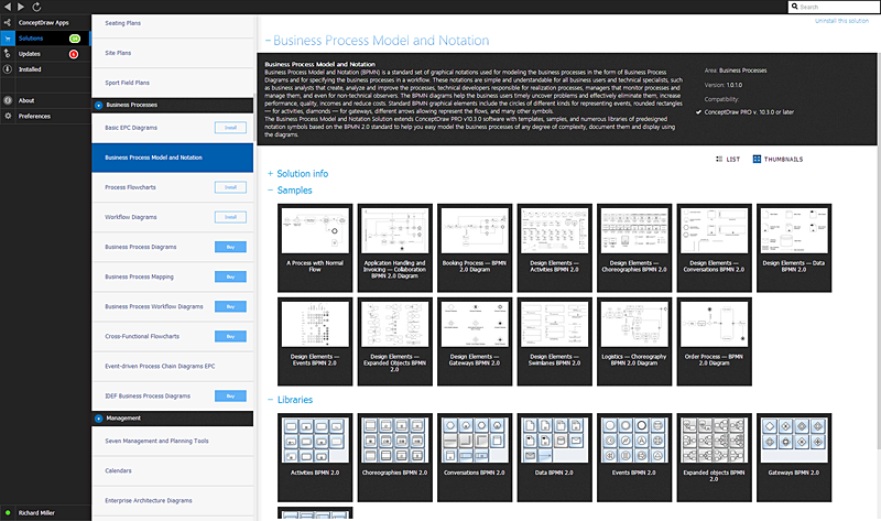
ConceptDraw Office for Windows Installation Definition
With the introduction of version 3, ConceptDraw Office has been redesigned to better accommodate future developments and solution plugins. ConceptDraw Office 3 includes ConceptDraw PRO 10, ConceptDraw MINDMAP 8, and ConceptDraw PROJECT 7. Owners of ConceptDraw Office v1 and ConceptDraw Office v2, please read this description of the specific features of the ConceptDraw Office 3 installation for Windows before updating.Managing the task list
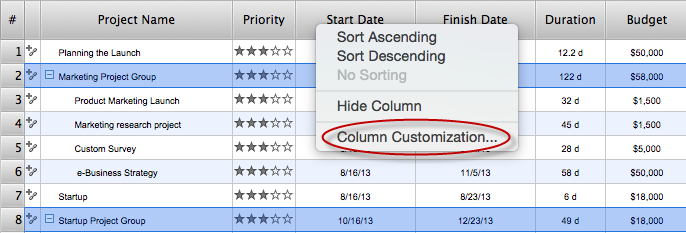
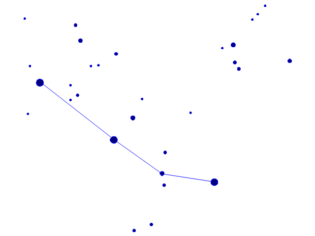
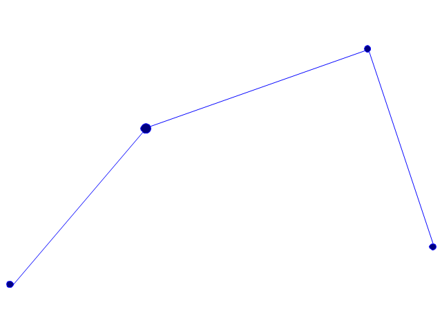
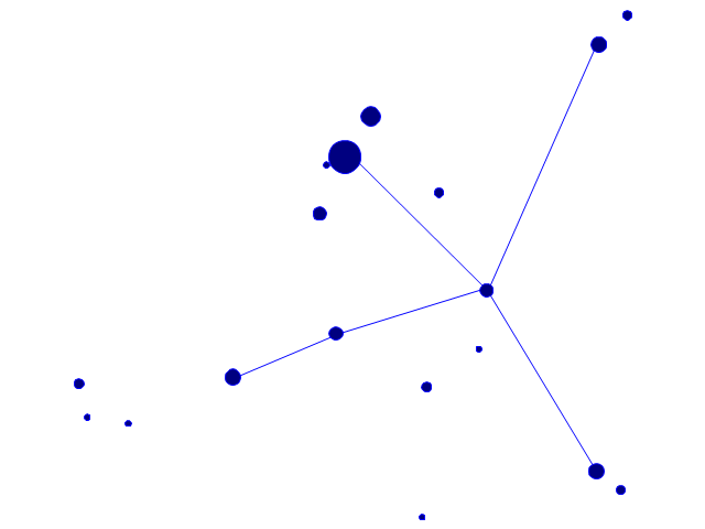
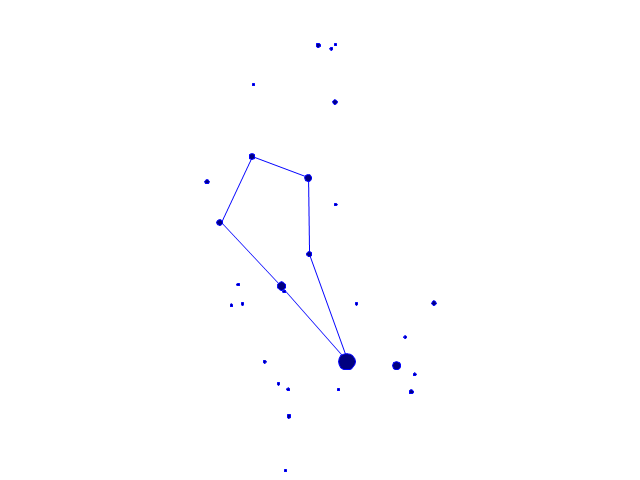
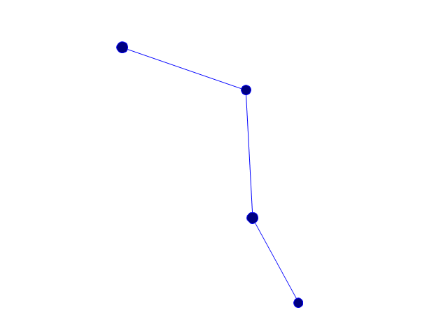
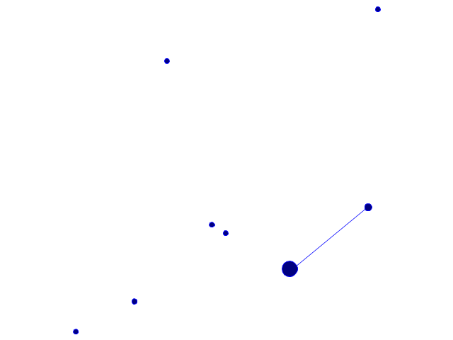
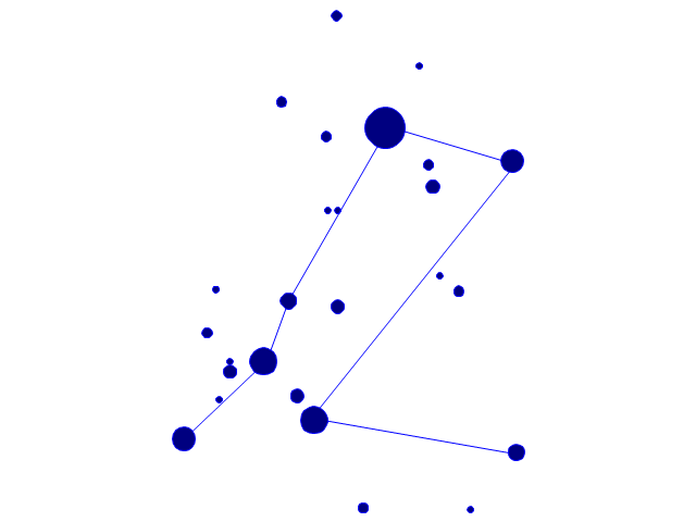
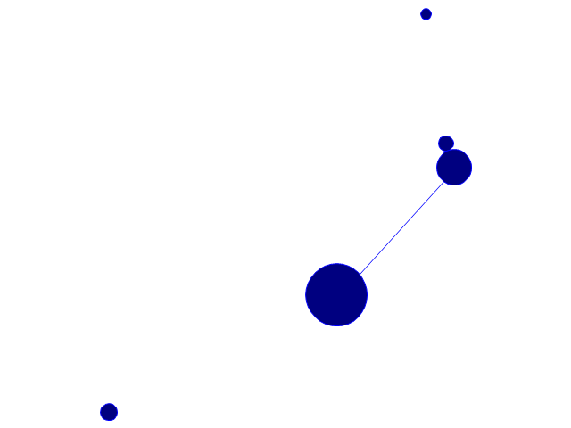
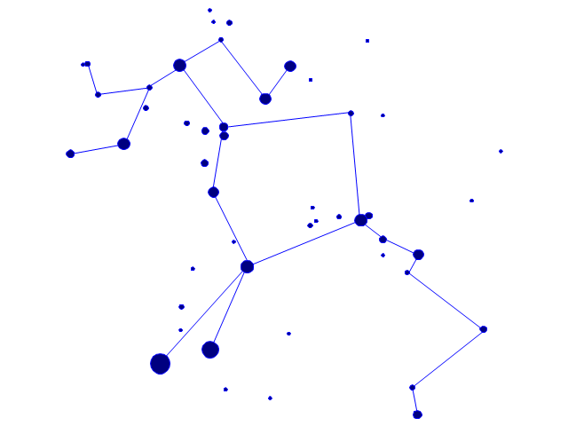
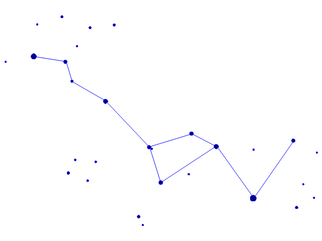
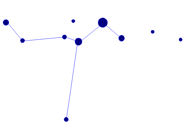
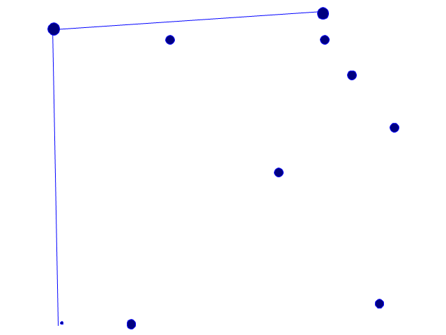
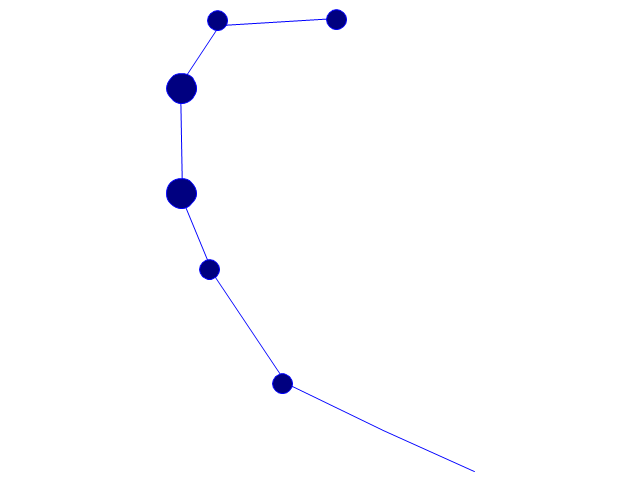
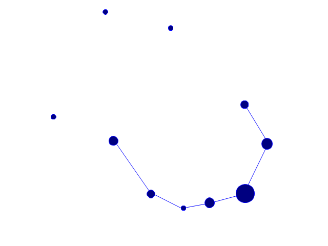
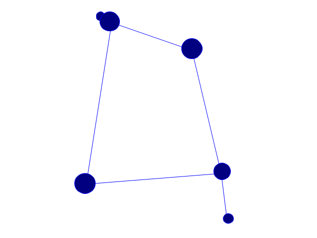
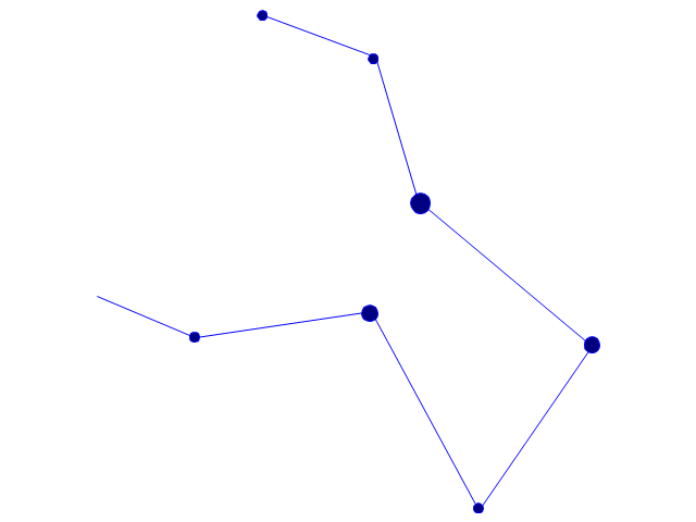
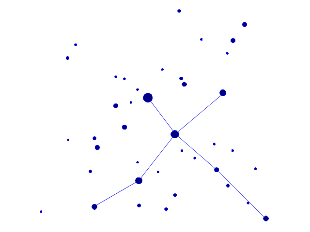
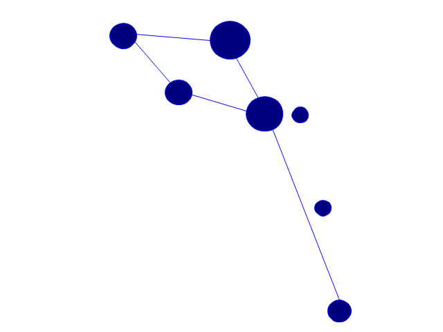
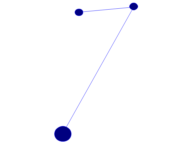
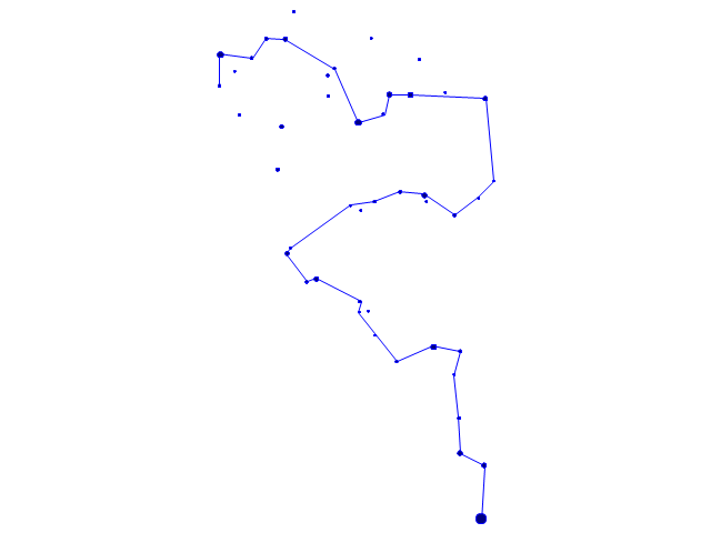
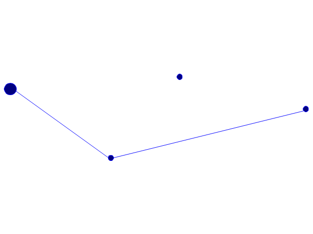
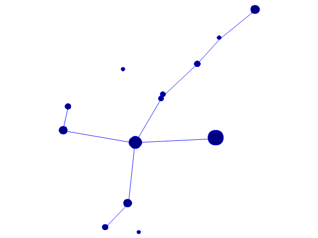
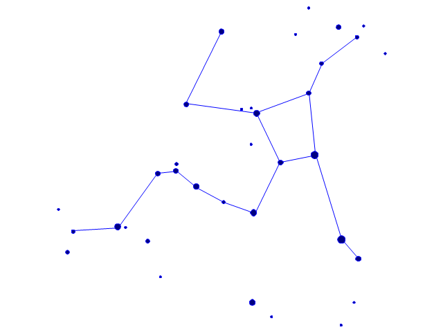
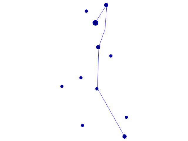
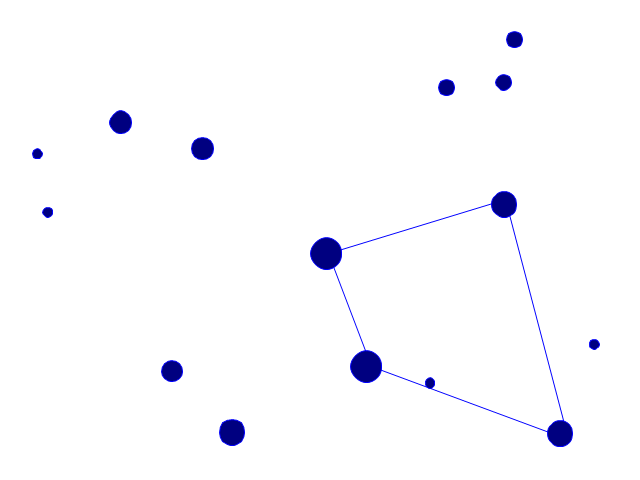
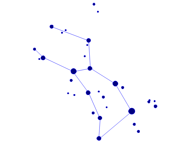
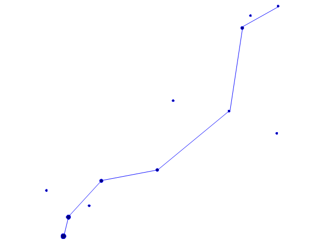
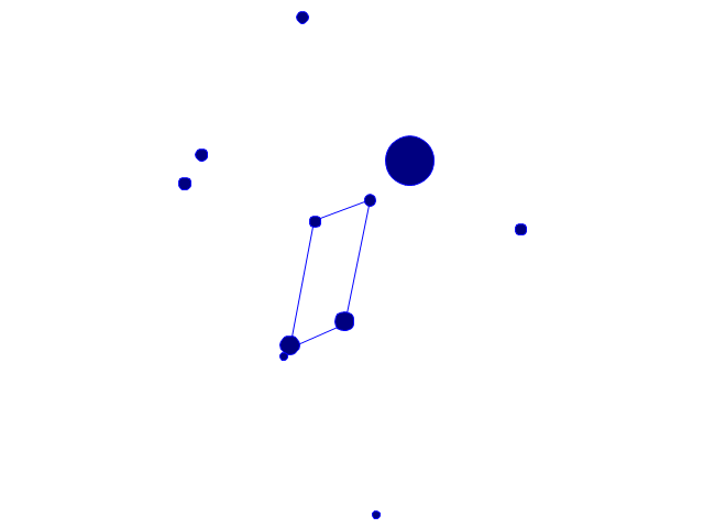
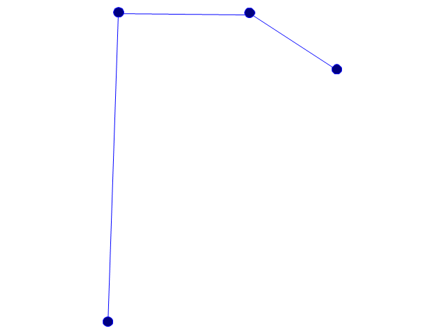
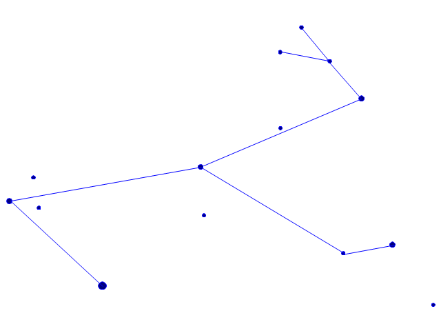
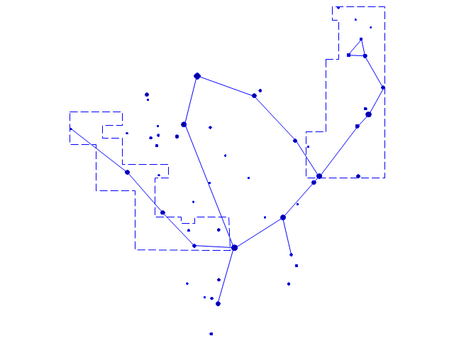
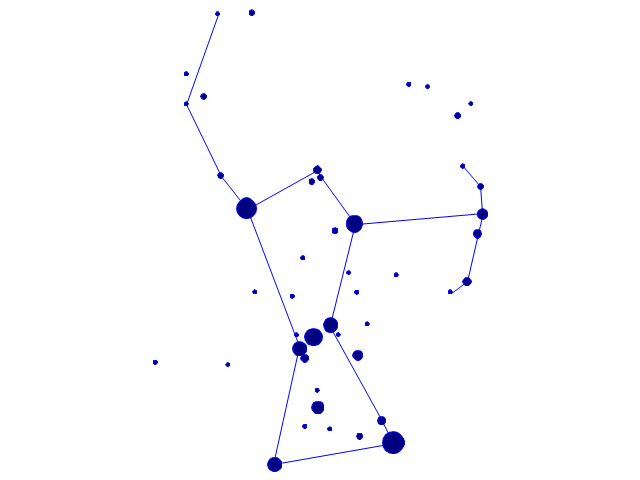
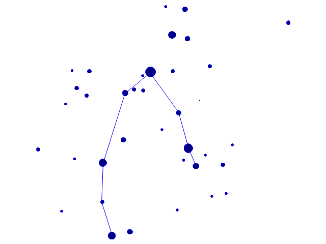
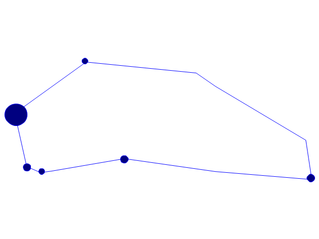
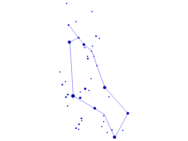
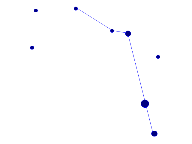
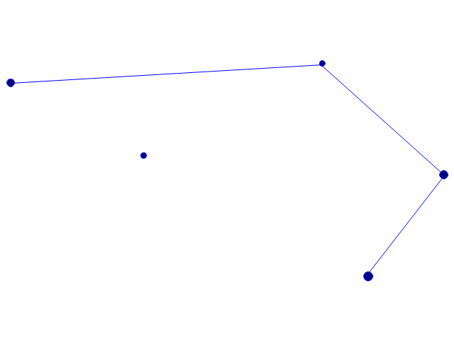
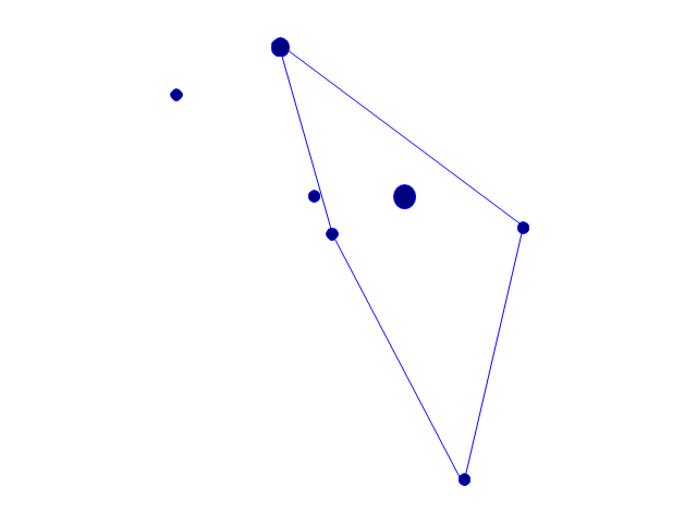
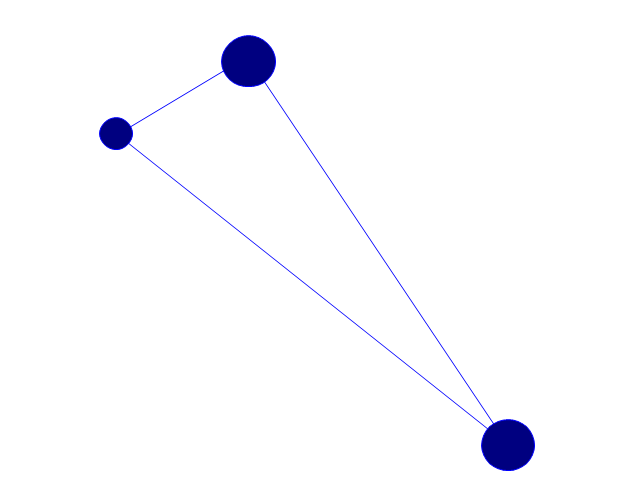
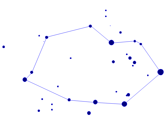
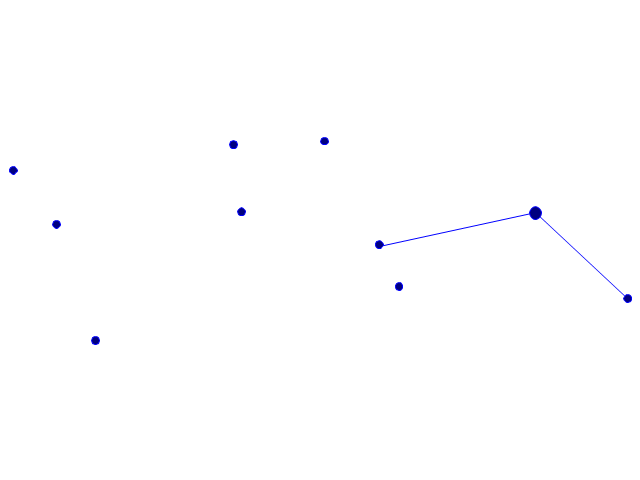
Four lessons explaining how to manage your task list in a Gantt chart. You will learn how to adjust your Gantt chart view, how to add/delete tasks or subtasks, how to change tasks hierarchy, how to show/hide subtasks.The vector stencils library "Constellations except Zodiac, Northern and Southern" contains 47 star constellation maps of all constellations except Zodiac, Northern (45-90 degrees) and Southern (45-90 degrees).
Use these shapes for drawing astronomical diagrams and illustrations in ConceptDraw PRO diagramming and vector drawing software extended with the Astronomy solution from the Science and Education area in ConceptDraw Solution Park.
Use these shapes for drawing astronomical diagrams and illustrations in ConceptDraw PRO diagramming and vector drawing software extended with the Astronomy solution from the Science and Education area in ConceptDraw Solution Park.
HelpDesk
ConceptDraw Office for Apple macOS Installation Definition
With the introduction of version 3, ConceptDraw Office has been redesigned to better accommodate future developments and solution plugins. ConceptDraw Office 3 includes ConceptDraw PRO 10, ConceptDraw MINDMAP 8, and ConceptDraw PROJECT 7. The renewed ConceptDraw STORE helps user manage downloads of ConceptDraw products and solutions. The following article provides owners of the previous versions of ConceptDraw products with important information on updating on ConceptDraw Office v3.- Design elements - Thematic maps | Name Three Primary Purposes ...
- All Mechanical Engineering Symbols Name
- Solid Figure And Its Name
- Name Standard Flowchart Symbols
- Design elements - Solid geometry | Pentagonal Cylinder Name
- Mechanical Engineering Name Symbol
- Pyramid Chart Examples | Diagram Of An Estate Firm Name And ...
- Name The Various Types Of Resources With Flow Chart
- Name And Explain Two Types Of Flowchart
- The Name Of Laboratory Apparatus With Diagram
- Ice Hockey | Ice Hockey Ground Name
- Name Of All The Glass Ware Equipment In The Laboratory
- Network Glossary Definition | Continent Maps | Name Resolution ...
- All Mechanical Symoble Name
- Draw 20 Flow Chart With Their Name Uses Or Function
- Name The Asian Countries
- Process Flowchart | Instroment Of Electrical Equepment Name
- Diagrams And Name Of Road Sign
- Industrial Wiring Diagram Symbols With Name
- Basic Flowchart Symbols and Meaning | Picture And Name Geometry
