Network Diagram Software. LAN Network Diagrams. Physical Office Network Diagrams
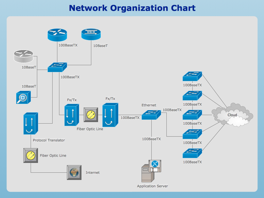
Physical LAN Diagrams illustrate the communication schemes of Local Area Networks, the physical network connection of computers and networks arrangement on the small areas - at homes, offices, and other buildings. ConceptDraw DIAGRAM is a perfect network diagramming software with samples and examples of WAN and LAN Diagrams, templates and collection of network components libraries. Computer Network Diagrams Solution for ConceptDraw DIAGRAM Mac and Windows is ideal for IT professionals, network engineers and network designers who need to visualize network architecture, to document LANs physical structure and arrangement, to draw Local Area Network (LAN) diagrams and schematics, WAN diagrams, physical office network diagrams and topologies, wiring drawings, etc. You can design all them easy using the predesigned vector objects of computers and computer network devices, hardware devices, peripheral devices, external digital devices, internet and logical symbols, and many other stencils from the Computer Network Diagrams libraries. ConceptDraw DIAGRAM offers a powerful and easy-to-use solution for those who looking for a Visio alternative for Mac. It is a world-class diagramming platform with dynamic presentation power.
Find out what amount and type of equipment is needed for your office network
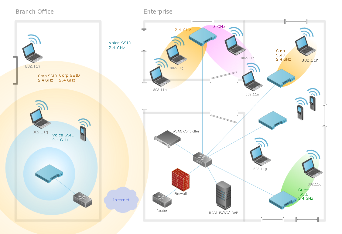
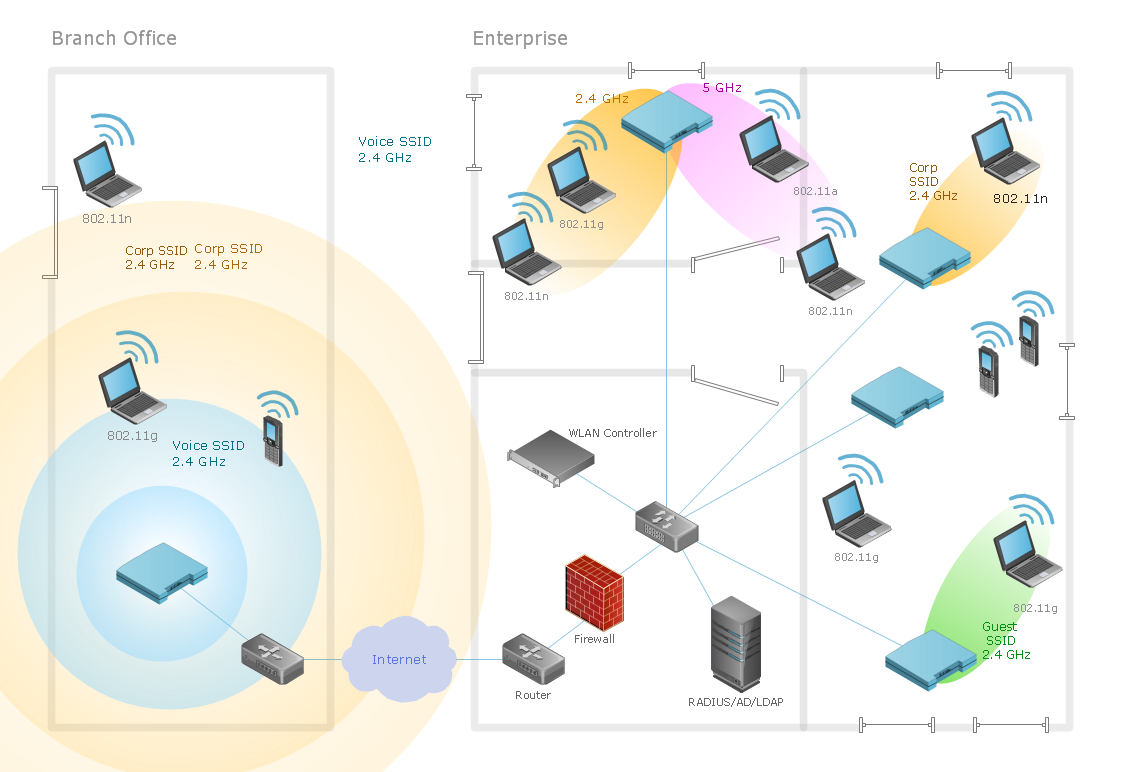
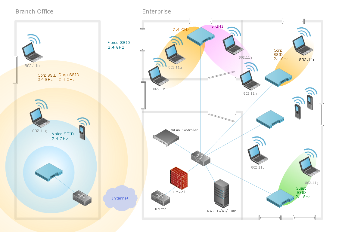
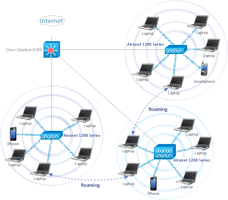
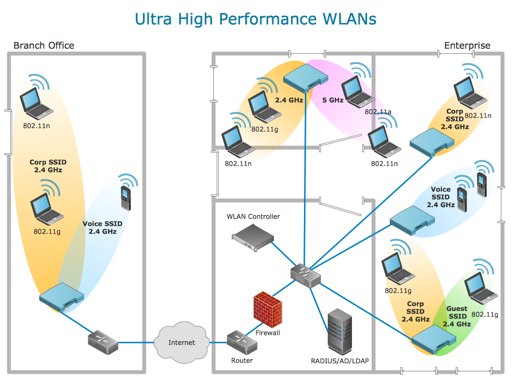
Wireless computer network diagrams help system administrators and network engineers to find out amount and type of equipment needed for each office WLAN.
Computer Network of an Office
The network engineers can use the Wireless Networks solution for making diagram of the wireless network of an office.
 Office Layout Plans
Office layouts and office plans are a special category of building plans and are often an obligatory requirement for precise and correct construction, design and exploitation office premises and business buildings. Designers and architects strive to make office plans and office floor plans simple and accurate, but at the same time unique, elegant, creative, and even extraordinary to easily increase the effectiveness of the work while attracting a large number of clients.
 Network Layout Floor Plans
Network Layout Floor Plans solution extends ConceptDraw DIAGRAM software functionality with powerful tools for quick and efficient documentation the network equipment and displaying its location on the professionally designed Network Layout Floor Plans. Never before creation of Network Layout Floor Plans, Network Communication Plans, Network Topologies Plans and Network Topology Maps was not so easy, convenient and fast as with predesigned templates, samples, examples and comprehensive set of vector design elements included to the Network Layout Floor Plans solution. All listed types of plans will be a good support for the future correct cabling and installation of network equipment.
The vector stencils library "Telecommunication networks" contains 32 clipart images of telecommunication network devices and equipment for drawing telecom network diagrams.
"A telecommunications network is a collection of terminal nodes, links and any intermediate nodes which are connected so as to enable telecommunication between the terminals.
The transmission links connect the nodes together. The nodes use circuit switching, message switching or packet switching to pass the signal through the correct links and nodes to reach the correct destination terminal.
Each terminal in the network usually has a unique address so messages or connections can be routed to the correct recipients. The collection of addresses in the network is called the address space." [Telecommunications network. Wikipedia]
The clip art example "Telecommunication networks - Vector stencils library" was created using the ConceptDraw PRO diagramming and vector drawing software extended with the Telecommunication Network Diagrams solution from the Computer and Networks area of ConceptDraw Solution Park.
Building Networks
The ConceptDraw DIAGRAM is a best Network Diagramming software.Network Drawing Software
ConceptDraw Network Drawing Software - Network design software for network drawings with abundant examples and templates. Create computer network designs, diagrams and schematics using ConceptDraw.
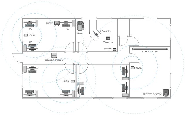
This office floor plan sample depicts the equipment layout of wireless computer network.
"A wireless local area network (WLAN) links two or more devices using some wireless distribution method (typically spread-spectrum or OFDM radio), and usually providing a connection through an access point to the wider Internet. This gives users the ability to move around within a local coverage area and still be connected to the network. Most modern WLANs are based on IEEE 802.11 standards, marketed under the Wi-Fi brand name." [Wireless LAN. Wikipedia]
The equipment layout example "Office wireless network plan" was created using the ConceptDraw DIAGRAM diagramming and vector drawing software extended with the Office Layout Plans solution from the Building Plans area of ConceptDraw Solution Park.
What Is a Wireless Network?
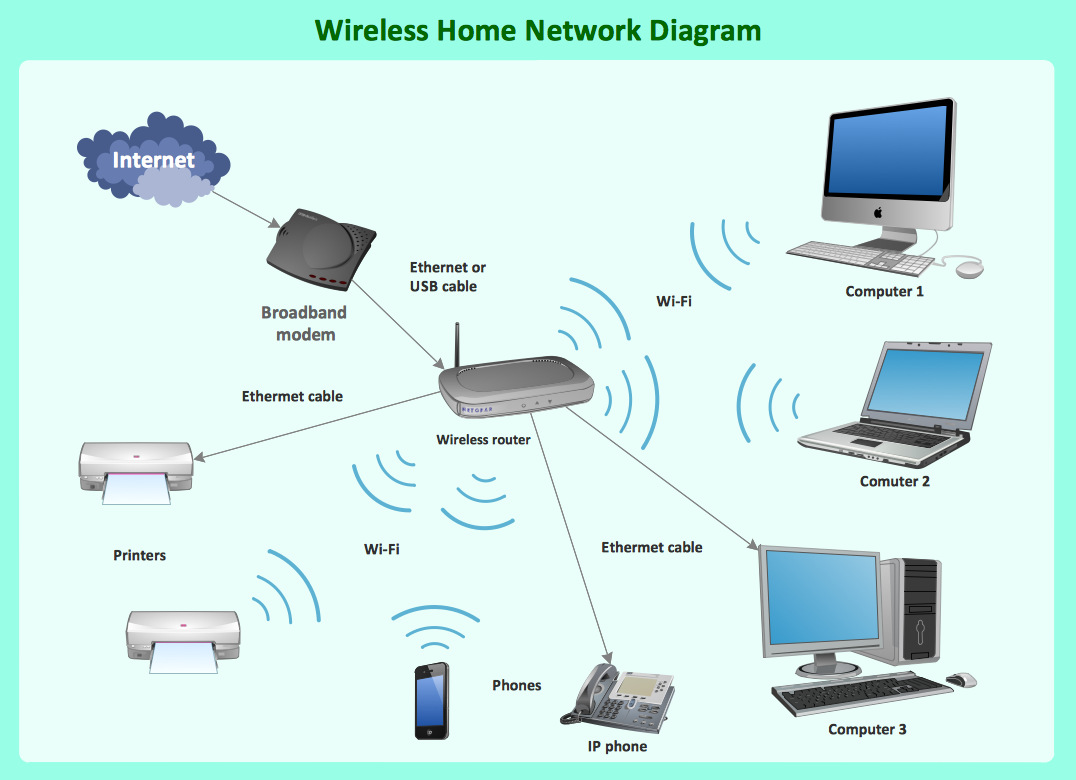
What Is a Wireless Network? Wireless network refers to any type of computer network that uses wireless (usually, but not always radio waves) for network connections. Wireless computer network diagrams help system administrators and network engineers to find out amount and type of equipment needed for each office WLAN.Diagram of a Wireless Network
ConceptDraw DIAGRAM is a Wireless Network Drawing software to create and illustrate wireless network diagrams.Wireless Network WLAN
ConceptDraw Wireless network diagram helps network engineer to design, mount and support WLAN or WWAN.How To use Architect Software
Professional building design and architect software are very popular among the modern designers, architects, and builders. They help visualize the building ideas, building concepts, effectively develop detailed building and architect design projects. ConceptDraw DIAGRAM diagramming and vector drawing software supplied with extensive Building Plans area is a powerful architect software. It allows professionally design and construct your home, office, school, shop, deck or landscape in a few minutes. It is a fastest way to create the Building plans, Floor plans, Home Floor plans, Electrical diagrams, Landscapes, Facility plans, Store layouts, and many other plans, drawings, and designs. You can use a lot of built-in templates, samples and examples offered by the building solutions of ConceptDraw Solution Park, we recommend to start with the exact template you need, then customize it with large variety of predesigned vector stencils to fit your needs, this lets to find an expected result quickly and without efforts.
Using Remote Networking Diagrams
Remote Networking - We explain the method most people use to connect to the Internet.
- Network Layout Floor Plans | Network Layout | Wireless Networks ...
- Network Layout Floor Plans | Office wireless network plan ...
- Sample Layout Plan Of Networking Computers In Offices Lan
- Wireless Networks | Building Networks | Wireless Network Drawing ...
- Office Network Diagram
- Small Office Network Design Diagram Pdf
- Interior Design Office Layout Plan Design Element | Building ...
- Office Building Networks Design Diagrams Pdf
- Example Of Microsoft Office Visio Computer Layout
- Network Layout Floor Plans | Network Layout | Office Layout Plans ...
- Logical network topology diagram | Network Diagram Software ...
- Office Wireless Network Diagram
- Computer Networking Sample Program
- Network Layout Floor Plans | Office wireless network plan | Network ...
- Office Wireless Computer Network Layout Plan
- Network Diagram Software LAN Network Diagrams & Diagrams for
- How To Interpret Network Diagram
- How to Create Network Diagrams
- Local area network (LAN). Computer and Network Examples ...

