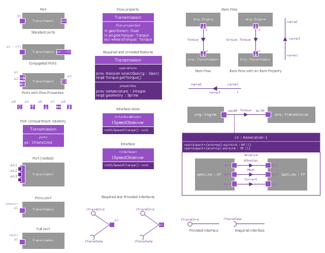
The vector stencils library "Ports and Flows" contains 26 SysML symbols.
Use it to design your SysML diagrams using ConceptDraw PRO diagramming and vector drawing software.
"The main motivation for specifying ports and flows is to enable design of modular, reusable blocks with clearly defined
ways of connecting and interacting with their context of use. This clause extends UML ports to support nested ports, and
extends blocks to support flow properties, and required and provided features, including blocks that type ports. Ports can be typed by blocks that support operations, receptions, and properties as in UML. SysML defines a specialized form of Block (InterfaceBlock) that can be used to support nested ports. SysML identifies two kinds of ports, one that exposes
features of the owning block or its internal parts (proxy ports), and another that supports its own features (full ports). Default compatibility rules are defined for connecting blocks used in composite structure, including parts and ports, with association blocks available to define more specific ways of doing this. These additional capabilities in SysML enable modelers to specify a wide variety of interconnectable components, which can be implemented through many engineering and social techniques, such as software, electrical or mechanical components, and human organizations. This clause also extends UML information flows for specifying item flows across connectors and associations." [www.omg.org/ spec/ SysML/ 1.3/ PDF]
The SysML shapes example "Design elements - Ports and Flows" is included in the SysML solution from the Software Development area of ConceptDraw Solution Park.
Best Tool for Infographic Construction
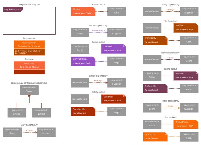
ConceptDraw is a best data visualization tool that will allow everyone to create rich infographics and visualizations quickly and easily.The vector stencils library "Requirement diagram" contains 21 SysML symbols.
Use it to design your requirement diagrams using ConceptDraw PRO diagramming and vector drawing software.
"A requirement specifies a capability or condition that must (or should) be satisfied. A requirement may specify a function that a system must perform or a performance condition a system must achieve. SysML provides modeling constructs to represent text-based requirements and relate them to other modeling elements. The requirements diagram described in this clause can depict the requirements in graphical, tabular, or tree structure format. A requirement can also appear on other diagrams to show its relationship to other modeling elements. The requirements modeling constructs are intended to provide a bridge between traditional requirements management tools and the other SysML models.
A requirement is defined as a stereotype of UML Class subject to a set of constraints. A standard requirement includes properties to specify its unique identifier and text requirement. Additional properties such as verification status, can be specified by the user.
Several requirements relationships are specified that enable the modeler to relate requirements to other requirements as well as to other model elements. These include relationships for defining a requirements hierarchy, deriving requirements, satisfying requirements, verifying requirements, and refining requirements." [www.omg.org/ spec/ SysML/ 1.3/ PDF]
The SysML shapes example "Design elements - Requirement diagram" is included in the SysML solution from the Software Development area of ConceptDraw Solution Park.
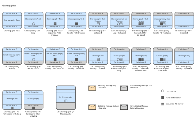
The vector stencils library "Choreographies" contains 28 symbols of choreography tasks, collapsed and expanded choreography sub-processes for drawing business process diagrams (BPMN 2.0).
"Choreography – Tasks performed by
participants and how participants
coordinate interactions via messages. ...
BPMN Choreography.
(1) Sequence of interactions between Participants.
(2) Choreographies exist outside of or in between Pools.
(3) A Choreography Task is an atomic Activity in a Choreography Process.
(4) The task represents an Interaction, which is one or two Message exchanges between two Participants.
(5) Helps to show who initiates the activity and the first message." [omg.org/ news/ meetings/ workshops/ SOA-HC/ presentations-2011/ 14_ MT-2_ Brookshier.pdf]
The shapes example "Design elements - Choreographies" is included in the Business Process Diagram solution from the Business Processes area of ConceptDraw Solution Park.
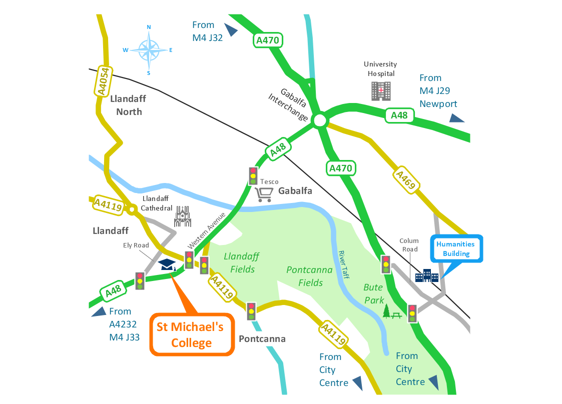
Spatial infographics Design Elements: Transport Map
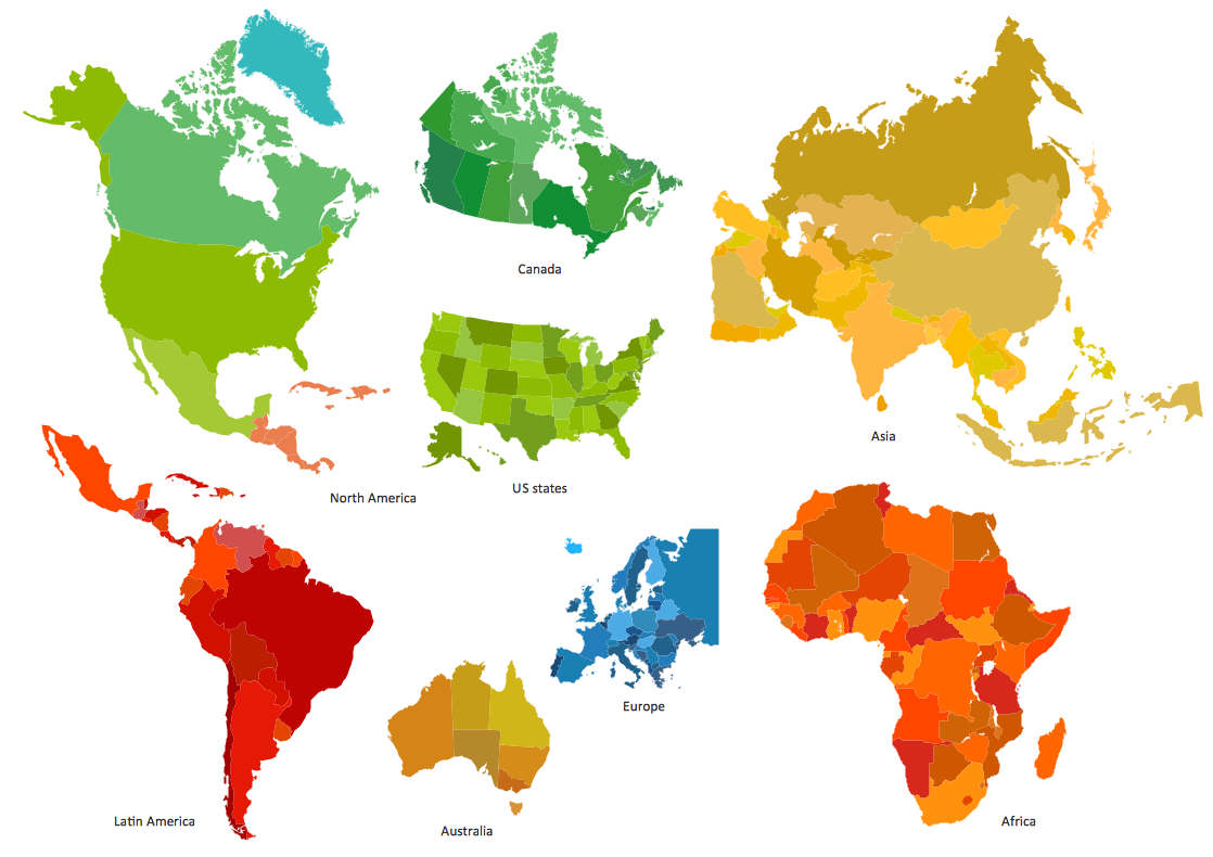
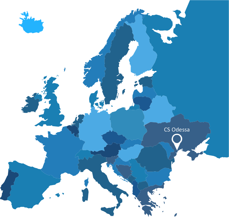
Do you like infographics and data visualization? Creating infographics is super-easy with ConceptDraw.Spatial infographics Design Elements: Continental Map
ConceptDraw PRO is a software for making infographics illustrations. You can work with various components to build really impressive and easy-to-understand infographics design.- Interior Design Machines and Equipment - Design Elements | How ...
- TOWS Matrix | Interior Design Site Plan - Design Elements ...
- Mechanical Engineering | Interior Design Piping Plan - Design ...
- Design elements - Sport fields and recreation | Cricket Pich Diagram ...
- When To Use a Fishbone Diagram | Fishbone Diagram Design ...
- Tqm Diagram Pdf
- Interior Design Piping Plan - Design Elements | Mechanical Drawing ...
- Mechanical Drawing Symbols | UML State Machine Diagram. Design ...
- Drawing Of Building Elements Pdf
- Technical Drawing Software | Mechanical Design Software | Interior ...
- Design elements - TCA cycle | Citric acid cycle (TCA cycle) | Biology ...
- Design Data Flow. DFD Library | DFD Library - Design elements ...
- Design elements - African country flags | African country flags ...
- Rail transport - Design elements | Passenger Railway Carriage ...
- Process Flowchart | Basic Flowchart Symbols and Meaning | Design ...
- Machine Design Symbol Pdf
- UML Component Diagram. Design Elements | Diagramming ...
- UML Component Diagram. Design Elements | UML Deployment ...
- UML State Machine Diagram. Design Elements | Mechanical ...
