HelpDesk
How to Draw a Floor Plan for Your Office
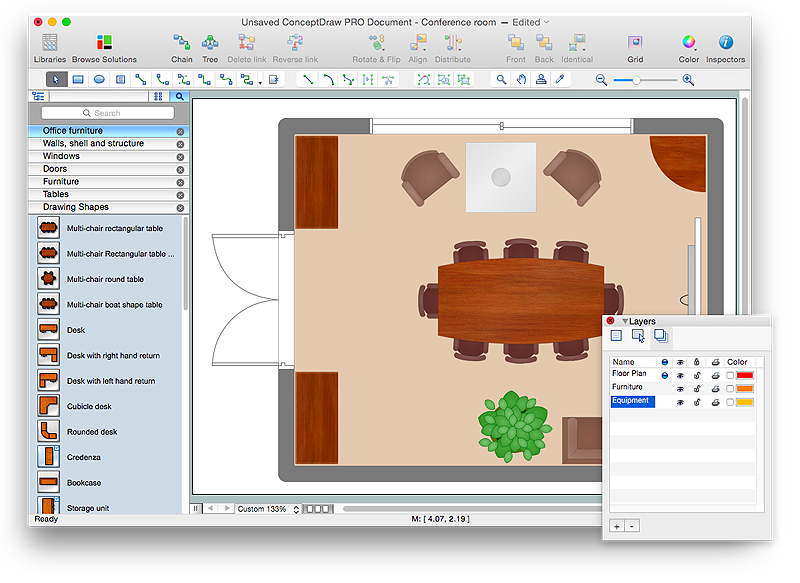
Designing the right office space is is an essential factor of business productivity. An office floor plan should reflect the needs of both employees and customers. ConceptDraw PRO allows you to draw the Floor Plan for your office using a special office equipment library as well as set of special objects that displays the sizes, corners, squares and other floor plan details.HelpDesk
How to Draw an Emergency Plan for Your Office
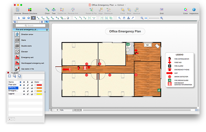
Emergency Floor Plan is important to supply an office staff with a visual safety solution. Emergency Floor Plan diagram presents a set of standard symbols used to depict fire safety, emergency, and associated information. Using clear and standard symbols on fire emergency plans delivers the coherence of collective actions , helps to avoid embarrassment, and improves communications in an emergent situation. The fire emergency symbols are intended for the general emergency and fire service, as well as for building plans ,engineering drawings and insurance diagrams. They can be used during fire extinguishing and evacuation operations, as well as training. It includes vector symbols for emergency management mapping, emergency evacuation diagrams and plans. You can use ConceptDraw PRO to make the fire evacuation plans for your office simple, accurate and easy-to-read.
"HVAC (stands for Heating, Ventilation and Air Conditioning) is a control system that applies regulation to a heating and/ or air conditioning system. Usually a sensing device is used to compare the actual state (e.g., temperature) with a target state. Then the control system draws a conclusion what action has to be taken (e.g., start the blower).
More complex HVAC systems can interface to Building Automation System (BAS) to allow the building owners to have more control over the heating or cooling units. The building owner can monitor the system and respond to alarms generated by the system from local or remote locations." [HVAC control system. Wikipedia]
The vector stencils library "HVAC control equipment" contains 48 symbols of heating, ventilation, air conditioning, refrigeration and automated building control equipment.
Use the design elements library HVAC control equipment to draw HVAC plans, schematic diagrams of heating, ventilation, air conditioning, refrigeration and automated building control systems, environmental control design building plans and equipment layouts using the ConceptDraw PRO diagramming and vector drawing software.
The shapes library HVAC control equipment is contained in the HVAC Plans solution from the Building Plans area of ConceptDraw Solution Park.
HelpDesk
How to Create a HVAC Plan
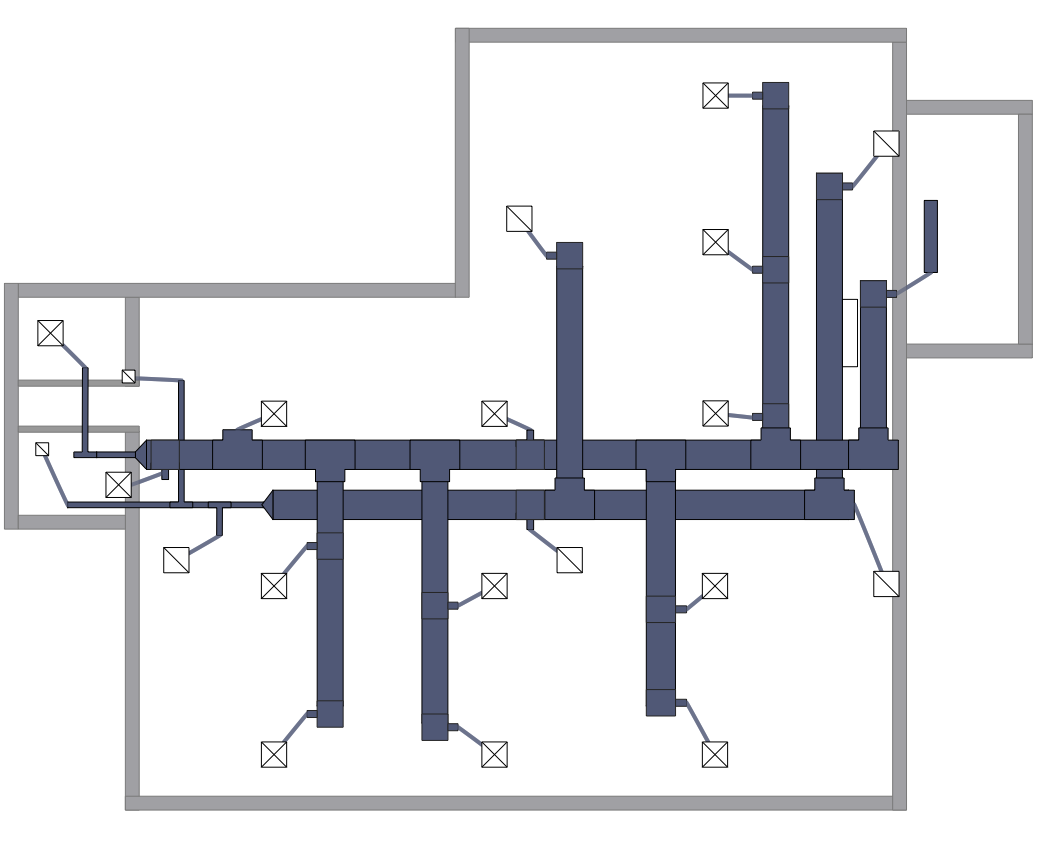
HVAC plans are used to make and maintain systems of a heating and air conditioning. HVAC plan is an important part of bulding planning. It is developed for privat family houses as well as for apartment and public buildings. Making HVAC plans as a part of construction documentation package essential requirement for any building project. Making a plan that shows the location and connection of HVAC equipment involves many different elements that can be managed using ConceptDraw PRO reinforced with HVAC Plans solution. With ConceptDraw PRO you can easily create and communicate HVAC plans of any complexity.- Office Layout Plans | Office Layout | Building Drawing Software for ...
- Equipment Used For Drawing Building Plan
- Gym and Spa Area Plans | Gym equipment layout floor plan | Gym ...
- Interior Design Office Layout Plan Design Element | Design ...
- Gym equipment layout floor plan | Building Drawing Software for ...
- Computer and Networks Area | Network Layout Floor Plans ...
- Cafe and Restaurant Floor Plan | How To use Furniture Symbols for ...
- Building Drawing Software for Design Office Layout Plan ...
- Plant Layout Plans | Building Drawing Software for Design Storage ...
- Electrical Drawing Software | How To use House Electrical Plan ...
- Lighting and switch layout | Design elements - Electrical and telecom
- Design elements - School layout plan | Classroom furniture and ...
- Plant Layout Plans | Building Drawing Software for Design Machines ...
- Which Equipment Uses For Interior Design
- Building Drawing Design Element: Piping Plan | Plumbing and ...
- Factory layout floor plan | ConceptDraw Solution Park | Floor Plan ...
- Plant Layout Plans | Factory layout floor plan | How To Draw ...
- Site accessories - Vector stencils library | Health club floor plan ...
- Floor Plan With Computer Networks
- Design elements - Day spa equipment layout plan | How to Draw a ...


