Electrical Symbols — VHF UHF SHF

Wireless Network Elements

The vector stencils library "VHF UHF SHF" contains 52 symbols for VHF, UHF, and SHF circuit design, including capacitance measurers, nonreciprocal devices, modulators, phase shifters, field polarization devices, and filters.
"Very high frequency (VHF) is the ITU-designated range of radio frequency electromagnetic waves from 30 MHz to 300 MHz, with corresponding wavelengths of one to ten meters. Frequencies immediately below VHF are denoted high frequency (HF), and the next higher frequencies are known as ultra high frequency (UHF).
Common uses for VHF are FM radio broadcasting, television broadcasting, land mobile stations (emergency, business, private use and military), long range data communication up to several tens of kilometres with radio modems, amateur radio, and marine communications. Air traffic control communications and air navigation systems (e.g. VOR, DME & ILS) work at distances of 100 kilometres or more to aircraft at cruising altitude.
VHF was previously used for analog television stations in the US." [Very high frequency. Wikipedia]
"Ultra-high frequency (UHF) designates the ITU radio frequency range of electromagnetic waves between 300 MHz and 3 GHz (3,000 MHz), also known as the decimetre band or decimetre wave as the wavelengths range from one to ten decimetres; that is 1 decimetre to 1 metre. Radio waves with frequencies above the UHF band fall into the SHF (super-high frequency) or microwave frequency range. Lower frequency signals fall into the VHF (very high frequency) or lower bands. UHF radio waves propagate mainly by line of sight; they are blocked by hills and large buildings although the transmission through building walls is high enough for indoor reception. They are used for television broadcasting (digital and analogue), cordless phones, walkie-talkies, satellite communication, and numerous other applications.
The IEEE defines the UHF radar band as frequencies between 300 MHz and 1 GHz. Two other IEEE radar band overlap the ITU UHF band: the L band between 1 and 2 GHz and the S band between 2 and 4 GHz." [Ultra high frequency. Wikipedia]
"Super high frequency (or SHF) is the ITU designation for radio frequencies (RF) in the range of 3 GHz and 30 GHz. This band of frequencies is also known as the centimetre band or centimetre wave as the wavelengths range from ten to one centimetres. These frequencies fall within the microwave band, so radio waves with these frequencies are called microwaves. The small wavelength of microwaves allows them to be directed in narrow beams by aperture antennas such as parabolic dishes, so they are used for point-to-point communication and data links, and for radar. This frequency range is used for most radar transmitters, microwave ovens, wireless LANs, cell phones, satellite communication, microwave radio relay links, and numerous short range terrestrial data links. The commencing wireless USB technology will be using approximately 1/ 3 of this spectrum.
Frequencies in the SHF range are often referred to by their IEEE radar band designations: S, C, X, Ku, K, or Ka band, or by similar NATO or EU designations." [Super high frequency. Wikipedia]
The shapes example "Design elements - VHF UHF SHF" was drawn using the ConceptDraw PRO diagramming and vector drawing software extended with the Electrical Engineering solution from the Engineering area of ConceptDraw Solution Park.
VHF, UHF, SHF symbols

Electrical Symbols — Transmission Paths

Audio Connectors

Total Quality Management Definition

Near field communication (NFC). Computer and Network Examples
. Computer and Network Examples")

Electrical Symbols — Qualifying

Electrical Symbols — Stations

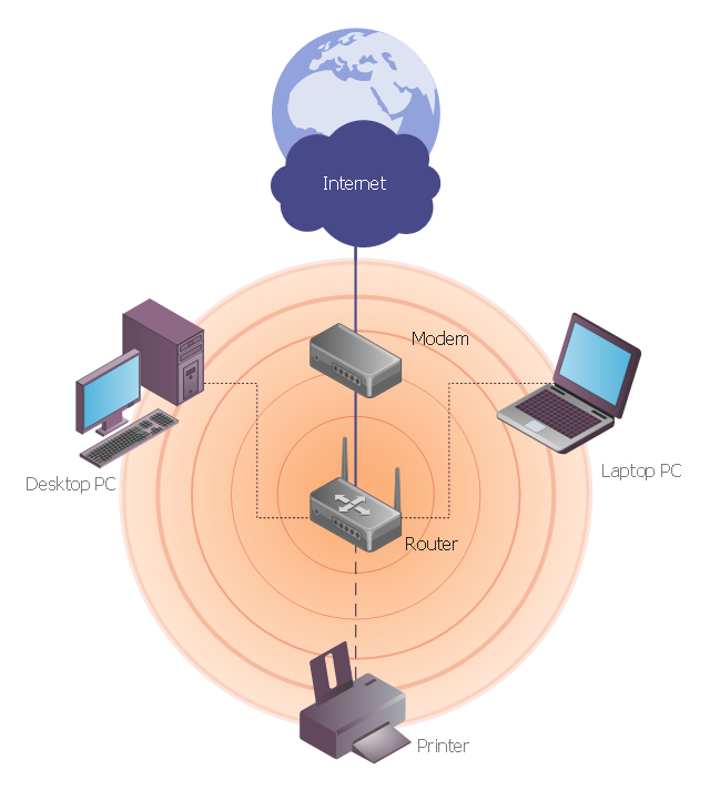
"In computer networking, a wireless access point (AP) is a device that allows wireless devices to connect to a wired network using Wi-Fi, or related standards. The AP usually connects to a router (via a wired network) as a standalone device, but it can also be an integral component of the router itself. ...
With the creation of the wireless Access Point (AP), network users are now able to add devices that access the network with few or no cables. An AP normally connects directly to a wired Ethernet connection and the AP then provides wireless connections using radio frequency links for other devices to utilize that wired connection. Most APs support the connection of multiple wireless devices to one wired connection. Modern APs are built to support a standard for sending and receiving data using, these radio frequencies. Those standards, and the frequencies they use are defined by the IEEE. Most APs use IEEE 802.11 standards." [Wireless access point. Wikipedia]
The wireless network diagram example "Wireless access point" was created using the ConceptDraw PRO diagramming and vector drawing software extended with the Wireless Networks solution from the Computer and Networks area of ConceptDraw Solution Park.
Wireless network diagram
Electrical Symbols — Semiconductor Diodes

The vector stencils library "Audio and video connectors" contains 94 symbols of audio and video connectors (TRS, TS, XLR, microphone, headphone, TOSLINK, DVI, VGA, DFP, S-Video, RCA, display port, HDMI, Thunderbolt, coaxial TV, F connector, MIDI) and device silhouettes.
Use these jacks and plugs clipart icons for drawing hook up diagrams.
"Audio connectors and video connectors are electrical connectors (or optical connectors) for carrying audio signal and video signal, of either analog or digital format. Analog A/ V connectors often use shielded cables to inhibit radio frequency interference (RFI) and noise." [Audio and video connector. Wikipedia]
"The existence of many different audio and video standards necessitates the definition of hardware interfaces, which define the physical characteristics of the connections between electrical equipment. This includes the types and numbers of wires required along with the strength and frequency of the signal. It also includes the physical design of the plugs and sockets.
An interface may define a connector that is used only by that interface (e.g., DVI) or may define a connector that is also used by another interface; for example, RCA connectors are defined both by the composite video and component video interfaces.
Audio connectors and video connectors are electrical connectors (or optical connectors) for carrying audio signal and video signal, of either analog or digital format. Analog A/ V connectors often use shielded cables to inhibit radio frequency interference (RFI) and noise.
Since both analog and digital signals are used with some styles of connectors, knowledge of the interface used is necessary for a successful transfer of signals. Some interface types use only a distinctive connector or family of connectors, to ensure compatibility. Especially with analog interfaces, physically interchangeable connectors may not carry compatible signals.
Some of these connectors, and other types of connectors, are also used at radio frequency (RF) to connect a radio or television receiver to an antenna or to a cable system..." [Audio and video interfaces and connectors. Wikipedia]
The clipart icons example "Design elements - Audio and video connectors" was created using the ConceptDraw PRO diagramming and vector drawing software extended with the Audio and Video Connectors solution from the Engineering area of ConceptDraw Solution Park.
Audio and video jacks and plugs

The vector stencils library "Transistors" contains 30 symbols of transistors drawing electronic schematics and circuit diagrams.
"A transistor is a semiconductor device used to amplify and switch electronic signals and electrical power. It is composed of semiconductor material with at least three terminals for connection to an external circuit. A voltage or current applied to one pair of the transistor's terminals changes the current through another pair of terminals. Because the controlled (output) power can be higher than the controlling (input) power, a transistor can amplify a signal. Today, some transistors are packaged individually, but many more are found embedded in integrated circuits.
The transistor is the fundamental building block of modern electronic devices, and is ubiquitous in modern electronic systems. ...
Transistors are categorized by:
(1) Semiconductor material...: the metalloids germanium ... and silicon ... in amorphous, polycrystalline and monocrystalline form; the compounds gallium arsenide ... and silicon carbide ..., the alloy silicon-germanium ..., the allotrope of carbon graphene ...
(2) Structure: BJT, JFET, IGFET (MOSFET), insulated-gate bipolar transistor, "other types"
(3) Electrical polarity (positive and negative): n–p–n, p–n–p (BJTs); n-channel, p-channel (FETs)
(4) Maximum power rating: low, medium, high
(5) Maximum operating frequency: low, medium, high, radio (RF), microwave frequency...
(6) Application: switch, general purpose, audio, high voltage, super-beta, matched pair
(7) Physical packaging: through-hole metal, through-hole plastic, surface mount, ball grid array, power modules...
(8) Amplification factor..." [Transistor. Wikipedia]
The shapes example "Design elements - Transistors" was drawn using the ConceptDraw PRO diagramming and vector drawing software extended with the Electrical Engineering solution from the Engineering area of ConceptDraw Solution Park.
Transistor symbols

The vector stencils library "Design elements - Electron tubes" contains 36 element symbols of electron tubes.
Use it for drawing electrical schematics and electronic circuit diagrams.
"One classification of vacuum tubes is by the number of active electrodes, (neglecting the filament or heater). A device with two active elements is a diode, usually used for rectification. Devices with three elements are triodes used for amplification and switching. Additional electrodes create tetrodes, pentodes, and so forth, which have multiple additional functions made possible by the additional controllable electrodes.
Other classifications are:
(1) by frequency range (audio, radio, VHF, UHF, microwave),
(2) by power rating (small-signal, audio power, high-power radio transmitting),
(3) by design (e.g., sharp- versus remote-cutoff in some pentodes),
(4) by application (receiving tubes, transmitting tubes, amplifying or switching, rectification, mixing),
(5) special qualities (long life, very low microphonic and low noise audio amplification, and so on).
Multiple classifications may apply to a device; for example similar dual triodes can be used for audio preamplification and as flip-flops in computers, although linearity is important in the former case and long life in the latter.
Tubes have different functions, such as cathode ray tubes which create a beam of electrons for display purposes (such as the television picture tube) in addition to more specialized functions such as electron microscopy and electron beam lithography. X-ray tubes are also vacuum tubes. Phototubes and photomultipliers rely on electron flow through a vacuum, though in those cases electron emission from the cathode depends on energy from photons rather than thermionic emission." [Vacuum tube. Wikipedia]
The symbols example "Design elements - Electron tubes" was drawn using the ConceptDraw PRO diagramming and vector drawing software extended with the Electrical Engineering solution from the Engineering area of ConceptDraw Solution Park.
Vacuum tubes

The design elements library "Cable TV" contains 64 symbols of CATV network equipment.
"Cable television is a system of distributing television programs to subscribers via radio frequency (RF) signals transmitted through coaxial cables or light pulses through fiber-optic cables. This contrasts with traditional broadcast television (terrestrial television) in which the television signal is transmitted over the air by radio waves and received by a television antenna attached to the television. FM radio programming, high-speed Internet, telephone service, and similar non-television services may also be provided through these cables.
The abbreviation CATV is often used for cable television." [Cable television. Wikipedia]
Use the shapes library "Cable TV" to draw CATV system design floor plans, network topology diagrams, wiring diagrams and cabling layout schemes using the ConceptDraw PRO diagramming and vector drawing software.
The vector stencils library "Cable TV" is included in the Electric and Telecom Plans solution from the Building Plans area of ConceptDraw Solution Park.
Cable TV symbols
.png--diagram-flowchart-example.png)
- Radio Frequency Png
- Radio Wave Images Png
- Radio Waves Image Png
- Coal Power Icon Png
- Radio Satellite Png
- Radar Dish Png
- Design elements - TV, Photo and Video | Standard Universal Audio ...
- Radar Aircraft Png
- Radio Signal Png
- Design elements - Android system icons (hardware) | TV, Photo and ...
- Frequency Icon Png
- Microwave Dish Antenna Png
- Vhf Radio Vector Png
- Png Hills
- Terrestrial Antenna Png
- Thunderbolt Icon Png
- Radar Wave Vector Png
- Hdmi Icon Png File
- Setallite Waves Png
- Wireless Wave Png