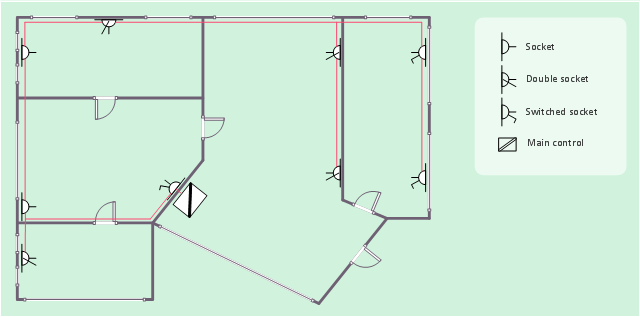
This electrical floot plan sample shows the Power socket outlet layout.
"The term plug is in general and technical use in all forms of English, common alternatives being power plug, electric plug, and (in the UK) plug top. The normal technical term (in both British and International English) for an AC power socket is socket-outlet, but in non-technical common use a number of other terms are used. In British English the general term is socket, but there are numerous common alternatives, including power point, plug socket, wall socket, and wall plug. In American English receptacle and outlet are common, sometimes with qualifiers such as wall outlet, electrical outlet and electrical receptacle, all of these sometimes to be found in the same document. A socket may be surrounded by a decorative and/ or protective cover called a wall plate, face plate, outlet cover, socket cover, or wall cover. In some designs this is an integral piece with the socket itself, bought and installed as a single unit." [AC power plugs and sockets. Wikipedia]
The electrical floot plan example "Power socket outlet layout" was created using the ConceptDraw PRO diagramming and vector drawing software extended with the Electric and Telecom Plans solution from the Building plans area of ConceptDraw Solution Park.
The vector stenvils library "Outlets" contains 57 symbols of electrical outlets.
Use these shapes for drawing building interior design, electrical floor plans and layouts of AC power plugs and sockets in the ConceptDraw PRO diagramming and vector drawing software.
The vector stencils library "Outlets" is included in the Electric and Telecom Plans solution from the Building Plans area of ConceptDraw Solution Park.
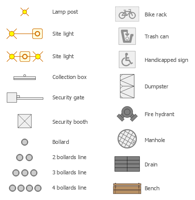
The design elements library Site accessories contains 18 symbols of vehicle access control equipment (tollbooth, tollgate, parking fees payment box), a handicapped sign, outdoor lighting, and garbage receptacles.
"A site plan is an architectural plan, landscape architecture document, and a detailed engineering drawing of proposed improvements to a given lot. A site plan usually shows a building footprint, travelways, parking, drainage facilities, sanitary sewer lines, water lines, trails, lighting, and landscaping and garden elements." [Site plan. Wikipedia]
Use the Site accessories library to design plans, equipment layouts and maps of sites, parking lots, residential and commercial landscapes, parks, yards, plats, outdoor recreational facilities, and irrigation systems using ConceptDraw PRO diagramming and vector drawing software.
The design elements library Site accessories is contained in the Site Plans solution from the Building Plans area of ConceptDraw Solution Park.
 Electric and Telecom Plans
This solution extends ConceptDraw PRO software with samples, templates and libraries of vector stencils for drawing the Electric and Telecom Plans.
 Reflected Ceiling Plans
Reflected Ceiling Plans solution is effective tool for architects, designers, electricians, and other people which every day need convenient tool for representing their ceiling ideas. Use it to create without efforts professional Reflected Ceiling plans and Reflective Ceiling plans, showing the location of light fixtures, drywall or t-bar ceiling patterns, lighting panels, and HVAC grilles and diffusers that may be suspended from the ceiling.
The vector stenvils library "Outlets" contains 57 symbols of electrical outlets.
Use these shapes for drawing building interior design, electrical floor plans and layouts of AC power plugs and sockets in the ConceptDraw PRO diagramming and vector drawing software.
The vector stencils library "Outlets" is included in the Electric and Telecom Plans solution from the Building Plans area of ConceptDraw Solution Park.
Use these shapes for drawing building interior design, electrical floor plans and layouts of AC power plugs and sockets in the ConceptDraw PRO diagramming and vector drawing software.
The vector stencils library "Outlets" is included in the Electric and Telecom Plans solution from the Building Plans area of ConceptDraw Solution Park.
- How To use House Electrical Plan Software | Outlets - Vector ...
- Power socket outlet layout | How To use House Electrical Plan ...
- Power socket outlet layout | Plant Layout Plans | How To use House ...
- Outlets - Vector stenvils library | Interior Design Site Plan - Design ...
- How To use House Electrical Plan Software | Power socket outlet ...
- How To use House Electrical Plan Software | Outlets - Vector ...
- How To use House Electrical Plan Software | Three Phase ...
- How To use House Electrical Plan Software | Design elements ...
- Interior Design Site Plan - Design Elements | How To use Electrical ...
- Power socket outlet layout | Electrical and Telecom Plan Software ...
- How To use House Electrical Plan Software | Electrical and Telecom ...
- How To use House Electrical Plan Software | Outlets - Vector ...
- Lighting and switch layout | Reflected ceiling plan | Classroom ...
- Power socket outlet layout | Cafe electrical floor plan | How To use ...
- How To use House Electrical Plan Software | Outlets - Vector ...
- Store Layout Software | Office Layout | Restaurant Floor Plan ...
- How To use Electrical and Telecom Plan Software | Outlets - Vector ...
- How To use House Electrical Plan Software | Design elements ...
- How To use House Electrical Plan Software | Interior Design Site ...
- Duplex Receptacle Symbol Iec


