The vector stencils library "HR symbols" contains 45 HR pictograms.
Use this icon set with HR symbols to draw your HR flowcharts, workflow diagrams, process charts and infographics with the ConceptDraw PRO diagramming and vector drawing software.
The HR pictograms library "HR symbols" is included in the HR Flowcharts solution from the Management area of ConceptDraw Solution Park.
The vector stencils library "Value stream mapping" contains 43 VSM symbols.
Use it for drawing value stream maps in the ConceptDraw PRO diagramming and vector drawing software extended with the Value Stream Mapping solution from the Quality area of ConceptDraw Solution Park.
www.conceptdraw.com/ solution-park/ business-value-stream-mapping
Use it for drawing value stream maps in the ConceptDraw PRO diagramming and vector drawing software extended with the Value Stream Mapping solution from the Quality area of ConceptDraw Solution Park.
www.conceptdraw.com/ solution-park/ business-value-stream-mapping
The vector stencils library "American football positions" contains 38 symbols for drawing diagrams of American football positions.
"In American football, each team has eleven players on the field at one time. The specific role that a player takes on the field is called their position. Under the modern rules of American football, teams are allowed unlimited substitutions, that is teams may change any number of players after any play. This has resulted in the development of three "platoons" of players, the offense (the team with the ball, who is trying to score), the defense (the team trying to prevent the other team from scoring, and to take the ball from them), and the special teams (who play in kicking situations). Within those platoons, various specific positions exist depending on what the player's main job is." [American football positions. Wikipedia]
The symbols example "Design elements - Football positions (for perspective view)" was created using the ConceptDraw PRO diagramming and vector drawing software extended with the Football solution from the Sport area of ConceptDraw Solution Park.
The vector stencils library "Fault tree analysis diagrams" contains 12 symbols for drawing Fault Tree Analysis (FTA) diagrams.
"Fault tree analysis (FTA) is a top down, deductive failure analysis in which an undesired state of a system is analyzed using Boolean logic to combine a series of lower-level events. This analysis method is mainly used in the fields of safety engineering and reliability engineering to understand how systems can fail, to identify the best ways to reduce risk or to determine (or get a feeling for) event rates of a safety accident or a particular system level (functional) failure. FTA is used in the aerospace, nuclear power, chemical and process, pharmaceutical, petrochemical and other high-hazard industries; but is also used in fields as diverse as risk factor identification relating to social service system failure.
In aerospace, the more general term "system Failure Condition" is used for the "undesired state" / Top event of the fault tree. These conditions are classified by the severity of their effects. The most severe conditions require the most extensive fault tree analysis. These "system Failure Conditions" and their classification are often previously determined in the functional Hazard analysis." [Fault tree analysis. Wikipedia]
The shapes example "Fault tree analysis diagrams" was created using the ConceptDraw PRO diagramming and vector drawing software extended with the Fault Tree Analysis Diagrams solution from the Engineering area of ConceptDraw Solution Park.
 Audit Flowcharts
Audit flowcharts solution extends ConceptDraw PRO software with templates, samples and library of vector stencils for drawing the audit and fiscal flow charts.
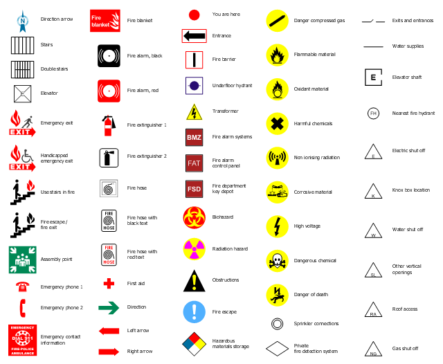
The design elements library "Fire and emergency planning" contains 52 fire safety symbols for developing the fire escape plans using the ConceptDraw PRO diagramming and vector drawing software.
The fire escape plan shows the location of fire alarm and extinguishing equipment, stairs and emergency exits, and evacuation orders and path.
"Hazard symbols are recognizable symbols designed to warn about hazardous materials, locations, or objects, including electric currents, poisons, and other things. The use of hazard symbols is often regulated by law and directed by standards organizations. Hazard symbols may appear with different colors, backgrounds, borders and supplemental information in order to specify the type of hazard." [Hazard symbol. Wikipedia]
The vector stencils library Fire and emergency planning is included in the Fire and Emergency Plans solution from the Building Plans" area of ConceptDraw Solution Park.
www.conceptdraw.com/ solution-park/ building-fire-emergency-plans
The vector stencils library "American football positions" contains 38 american football (gridiron) players symbols.
Use it for drawing diagrams of American football positions in the ConceptDraw PRO diagramming and vector drawing software extended with the Football solution from the Sport area of ConceptDraw Solution Park.
Use it for drawing diagrams of American football positions in the ConceptDraw PRO diagramming and vector drawing software extended with the Football solution from the Sport area of ConceptDraw Solution Park.
 ConceptDraw Solution Park
ConceptDraw Solution Park collects graphic extensions, examples and learning materials
HelpDesk
How to Create a Fault Tree Analysis Diagram (FTD) in ConceptDraw PRO
Fault Tree Diagram are logic diagram that shows the state of an entire system in a relationship of the conditions of its elements. Fault Tree Diagram are used to analyze the probability of functional system failures and safety accidents. ConceptDraw PRO allows you to create professional Fault Tree Diagrams using the basic FTD symbols. An FTD visualize a model of the processes within a system that can lead to the unlikely event. A fault tree diagrams are created using standard logic symbols . The basic elements in a fault tree diagram are gates and events.The vector stenvils library "Outlets" contains 57 symbols of electrical outlets for drawing building interior design, electrical floor plans and layouts of AC power plugs and sockets.
"AC power plugs and sockets are devices that allow electrically operated equipment to be connected to the primary alternating current (AC) power supply in a building. Electrical plugs and sockets differ in voltage and current rating, shape, size and type of connectors. The types used in each country are set by national standards, some of which are listed in the IEC technical report TR 60083, Plugs and socket-outlets for domestic and similar general use standardized in member countries of IEC.
Plugs and sockets for portable appliances started becoming available in the 1880s, to replace connections to light sockets with easier to use wall-mounted outlets. A proliferation of types developed to address the issues of convenience and protection from electric shock. Today there are approximately 20 types in common use around the world, and many obsolete socket types are still found in older buildings. Co-ordination of technical standards has allowed some types of plugs to be used over wide regions to facilitate trade in electrical appliances, and for the convenience of travellers and consumers of imported electrical goods. Some multi-standard sockets allow use of several different types of plugs; improvised or unapproved adapters between incompatible sockets and plugs may not provide the full safety and performance of an approved adapter." [AC power plugs and sockets. Wikipedia]
The example "Design elements - Outlets" was created using the ConceptDraw PRO diagramming and vector drawing software extended with the Electric and Telecom Plans solution from the Building plans area of ConceptDraw Solution Park.
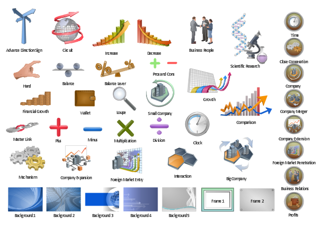
The vector clipart library "Presentation" design elements contains 45 symbols you can use to design your presentation slides and illustrations using the ConceptDraw PRO diagramming and vector drawing software.
"Although some think of presentations in a business meeting context, there are often occasions when that is not the case. For example, a non-profit organization presents the need for a capital fund-raising campaign to benefit the victims of a recent tragedy; a school district superintendent presents a program to parents about the introduction of foreign-language instruction in the elementary schools;an artist demonstrates decorative painting techniques to a group of interior designers; a horticulturist shows garden club members or homeowners how they might use native plants in the suburban landscape; a police officer addresses a neighborhood association about initiating a safety program. ...
A study done by Wharton School Of Business showed that the use of visuals reduced meeting times by 28 percent. Another study found that audiences believe presenters who use visuals are more professional and credible than presenters who merely speak. Other research indicates that meetings and presentations reinforced with visuals help participants reach decisions and consensus more quickly." [Presentation. Wikipedia]
The clip art example "Design elements - Presentation symbols" is included in the Presentation Clipart solution from the Illustration area of ConceptDraw Solution Park.
 Mechanical Engineering
This solution extends ConceptDraw PRO v.9 mechanical drawing software (or later) with samples of mechanical drawing symbols, templates and libraries of design elements, for help when drafting mechanical engineering drawings, or parts, assembly, pneumatic,
 Chemical and Process Engineering
This chemical engineering solution extends ConceptDraw PRO v.9.5 (or later) with process flow diagram symbols, samples, process diagrams templates and libraries of design elements for creating process and instrumentation diagrams, block flow diagrams (BFD
The vector stencils library "Valves and fittings" contains 104 symbols of valve components.
Use these icons for drawing industrial piping systems; process, vacuum, and fluids piping; hydraulics piping; air and gas piping; materials distribution; and liquid transfer systems.
"A valve is a device that regulates, directs or controls the flow of a fluid (gases, liquids, fluidized solids, or slurries) by opening, closing, or partially obstructing various passageways. Valves are technically valves fittings, but are usually discussed as a separate category. In an open valve, fluid flows in a direction from higher pressure to lower pressure.
The simplest, and very ancient, valve is simply a freely hinged flap which drops to obstruct fluid (gas or liquid) flow in one direction, but is pushed open by flow in the opposite direction. This is called a check valve, as it prevents or "checks" the flow in one direction. ...
Valves are found in virtually every industrial process, including water & sewage processing, mining, power generation, processing of oil, gas & petroleum, food manufacturing, chemical & plastic manufacturing and many other fields. ...
Valves may be operated manually, either by a handle, lever, pedal or wheel. Valves may also be automatic, driven by changes in pressure, temperature, or flow. These changes may act upon a diaphragm or a piston which in turn activates the valve, examples of this type of valve found commonly are safety valves fitted to hot water systems or boilers.
More complex control systems using valves requiring automatic control based on an external input (i.e., regulating flow through a pipe to a changing set point) require an actuator. An actuator will stroke the valve depending on its input and set-up, allowing the valve to be positioned accurately, and allowing control over a variety of requirements." [Valve. Wikipedia]
The example "Design elements - Valves and fittings" was created using the ConceptDraw PRO diagramming and vector drawing software extended with the Chemical and Process Engineering solution from the Engineering area of ConceptDraw Solution Park.
The vector stencils library Alarm and access control contains 80 symbols of digital proximity equipment, locking hardware, and access control equipment.
"An alarm device or system of alarm devices gives an audible, visual or other form of alarm signal about a problem or condition. Alarm devices are often outfitted with a siren." [Alarm device. Wikipedia]
"An access control point, which can be a door, turnstile, parking gate, elevator, or other physical barrier, where granting access can be electronically controlled. Typically, the access point is a door. An electronic access control door can contain several elements. At its most basic, there is a stand-alone electric lock. The lock is unlocked by an operator with a switch. To automate this, operator intervention is replaced by a reader. The reader could be a keypad where a code is entered, it could be a card reader, or it could be a biometric reader. Readers do not usually make an access decision, but send a card number to an access control panel that verifies the number against an access list. To monitor the door position a magnetic door switch can be used. In concept, the door switch is not unlike those on refrigerators or car doors. Generally only entry is controlled, and exit is uncontrolled. In cases where exit is also controlled, a second reader is used on the opposite side of the door. In cases where exit is not controlled, free exit, a device called a request-to-exit (REX) is used. Request-to-exit devices can be a push-button or a motion detector. When the button is pushed, or the motion detector detects motion at the door, the door alarm is temporarily ignored while the door is opened. Exiting a door without having to electrically unlock the door is called mechanical free egress. This is an important safety feature. In cases where the lock must be electrically unlocked on exit, the request-to-exit device also unlocks the door." [Access control. Wikipedia]
Use the design elements library Alarm and access control for drawing layout floor plans, blueprints, and wiring diagrams of intrusion systems, time and attendance systems, card and code access control security systems, internal and external security control systems using the ConceptDraw PRO diagramming and vector drawing software.
The shapes library Alarm and access control is included in the Security and Access Plans solution from the Building Plans area of ConceptDraw Solution Park.
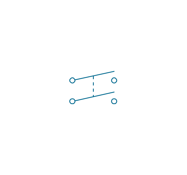
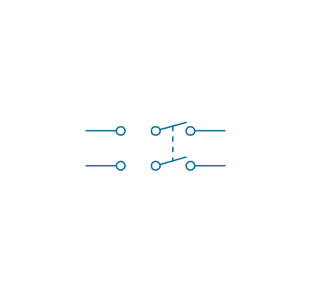
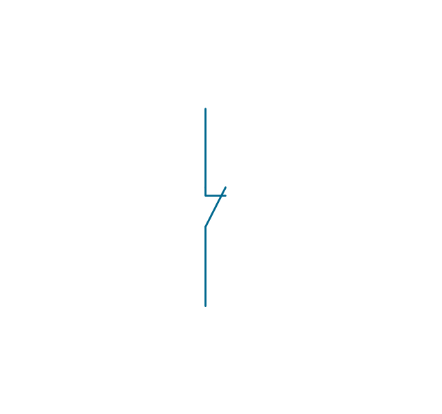
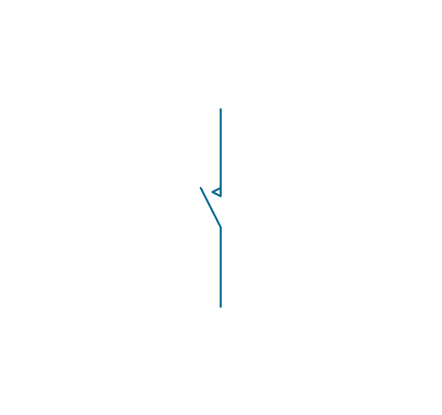
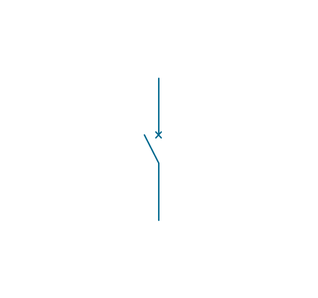
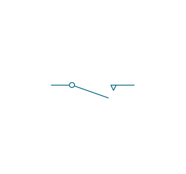
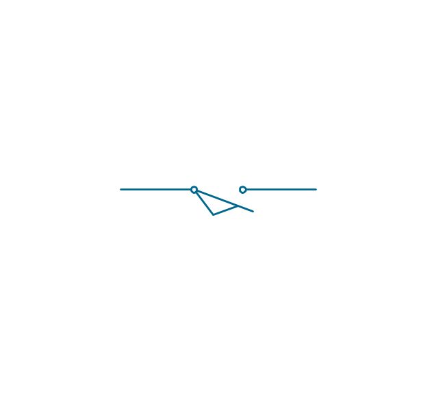
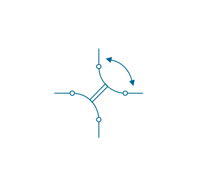
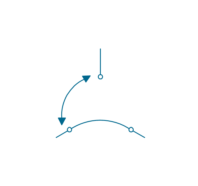
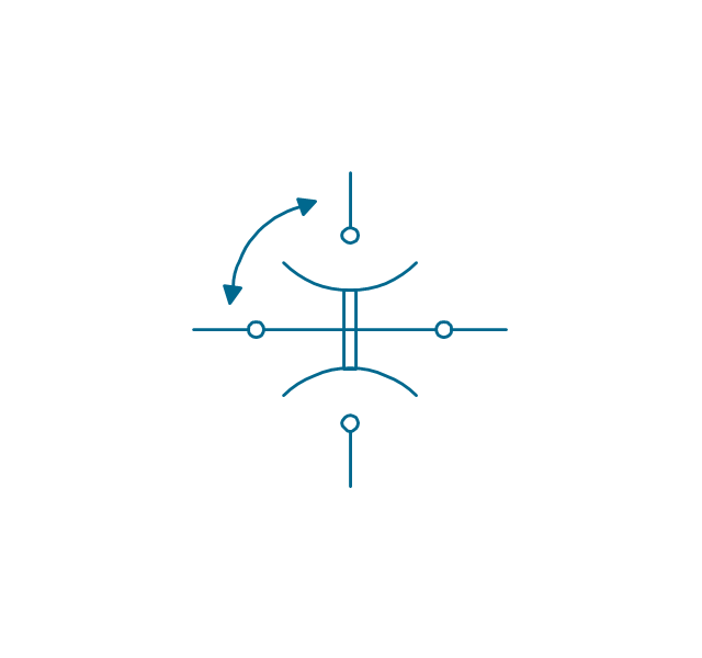
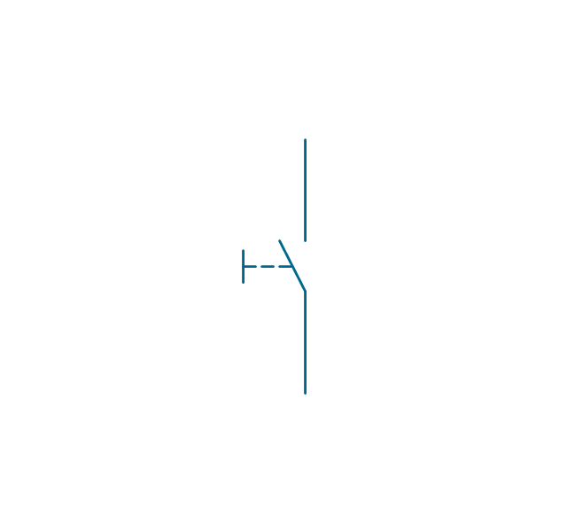
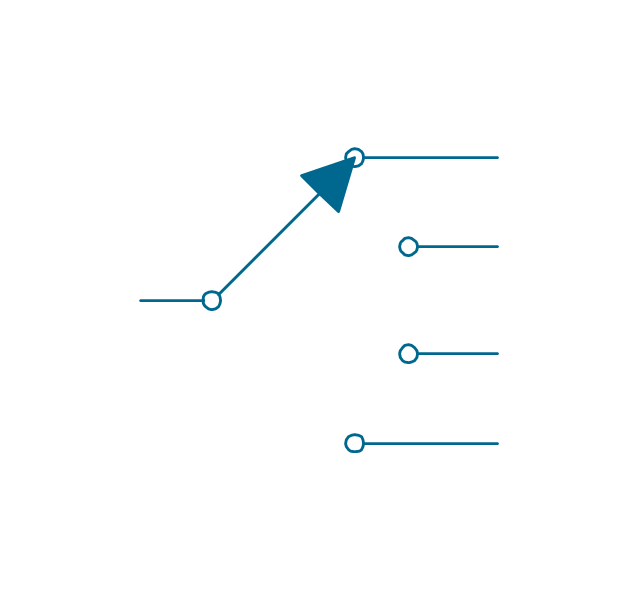
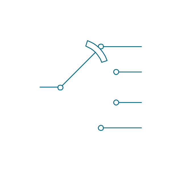
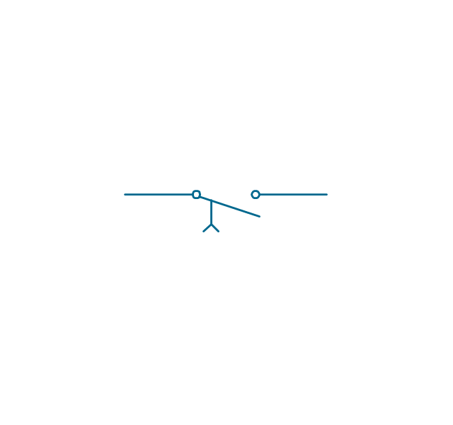
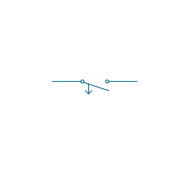
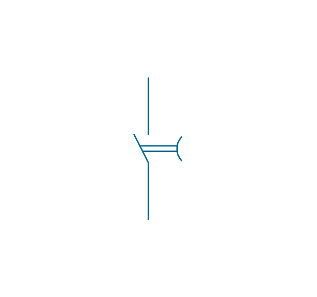
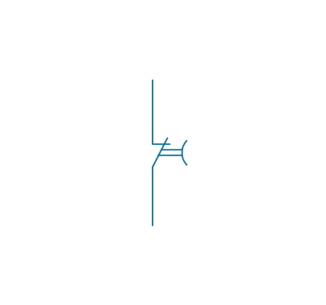
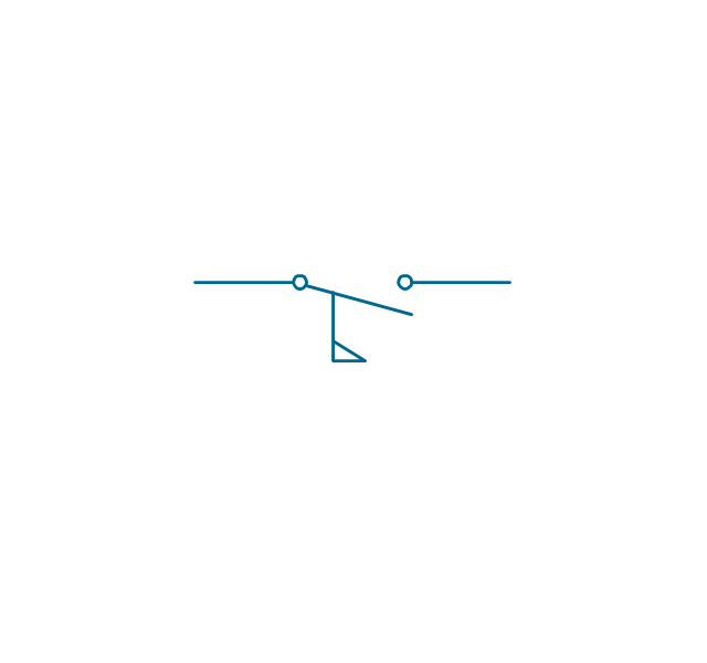
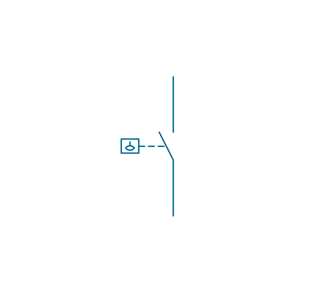
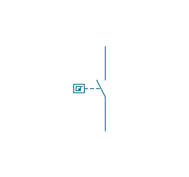
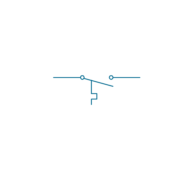
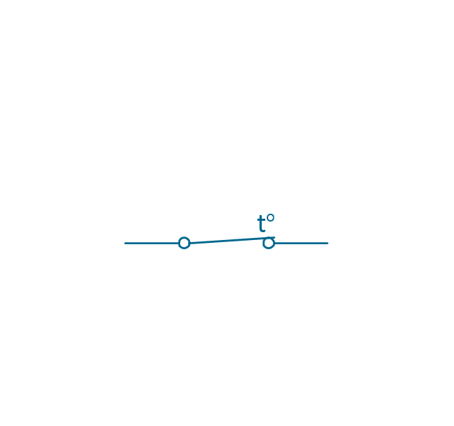
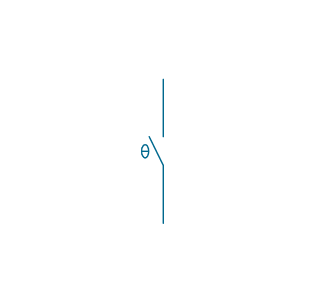
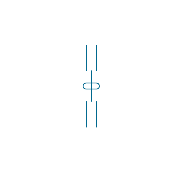
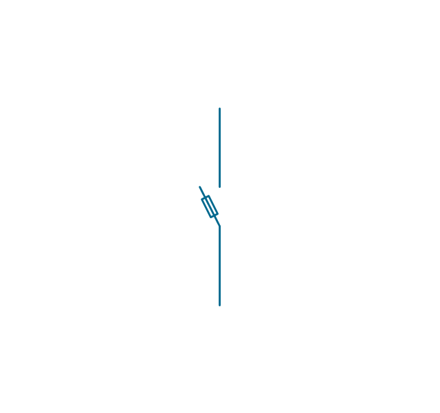
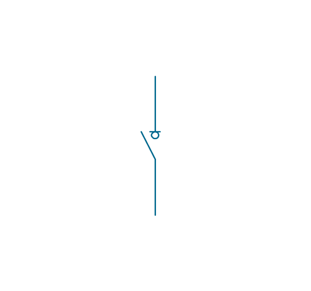
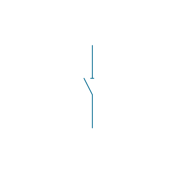
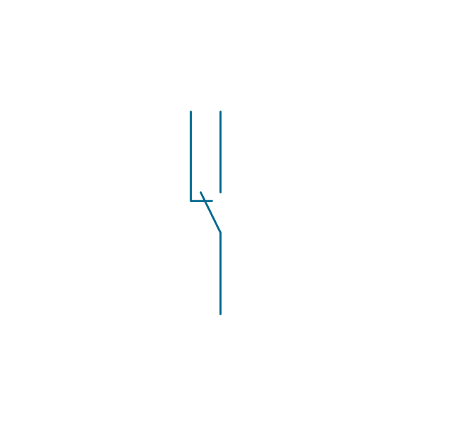
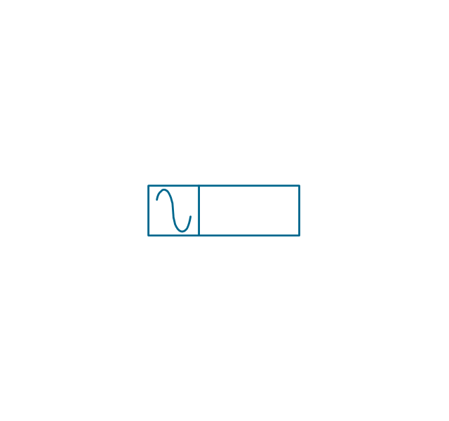
The vector stencils library "Switches and relays" contains 58 symbols of electrical contacts, switches, relays, circuit breakers, selectors, connectors, disconnect devices, switching circuits, current regulators, and thermostats for electrical devices.
Use these shapes for drawing electrical diagrams in the ConceptDraw PRO diagramming and vector drawing software extended with the Electrical Engineering solution from the Engineering area of ConceptDraw Solution Park.
www.conceptdraw.com/ solution-park/ engineering-electrical
Use these shapes for drawing electrical diagrams in the ConceptDraw PRO diagramming and vector drawing software extended with the Electrical Engineering solution from the Engineering area of ConceptDraw Solution Park.
www.conceptdraw.com/ solution-park/ engineering-electrical
- Fire and Emergency Plans | How To Create Emergency Plans | How ...
- Fire Safety Drawings
- Fire Safety Drawing Symbols
- How To Create Emergency Plans | Fire Exit Plan | How To Draw ...
- How To Draw Safety Symbols Of Fire
- Emergency Plan
- Electrical Engineering | Electrical Symbol For Safety Gate
- How to Draw an Emergency Plan for Your Office | Design elements ...
- Fire Safety Diagram
- Emergency Symbols For
- Gym and Spa Area Plans | Safety and Security | Audio, Video, Media ...
- Design elements - Initiation and annunciation | Design elements ...
- Safety and Security | Cisco Network Design. Cisco icons, shapes ...
- Universal Diagramming Area | Floorplan Safety Symbol Clipart
- Fire safety equipment - Vector stencils library | Basic Flowchart ...
- Fire safety equipment
- Safety and Security | Fire Exit Plan | How To Create Emergency ...
- Safety and Security | Security and Access Plans ... - Conceptdraw.com
- FTA diagram - Hazard analysis | Design elements - Fire and ...
- Safety and Security | Design elements - Fire safety equipment | Fire ...
























.png--diagram-flowchart-example.png)

-american-football-positions---vector-stencils-library.png--diagram-flowchart-example.png)
-american-football-positions---vector-stencils-library.png--diagram-flowchart-example.png)
-american-football-positions---vector-stencils-library.png--diagram-flowchart-example.png)
-american-football-positions---vector-stencils-library.png--diagram-flowchart-example.png)
-american-football-positions---vector-stencils-library.png--diagram-flowchart-example.png)
-american-football-positions---vector-stencils-library.png--diagram-flowchart-example.png)
-american-football-positions---vector-stencils-library.png--diagram-flowchart-example.png)
-american-football-positions---vector-stencils-library.png--diagram-flowchart-example.png)
-american-football-positions---vector-stencils-library.png--diagram-flowchart-example.png)
-american-football-positions---vector-stencils-library.png--diagram-flowchart-example.png)
-american-football-positions---vector-stencils-library.png--diagram-flowchart-example.png)
-american-football-positions---vector-stencils-library.png--diagram-flowchart-example.png)
-american-football-positions---vector-stencils-library.png--diagram-flowchart-example.png)
-american-football-positions---vector-stencils-library.png--diagram-flowchart-example.png)
-american-football-positions---vector-stencils-library.png--diagram-flowchart-example.png)
-american-football-positions---vector-stencils-library.png--diagram-flowchart-example.png)
-american-football-positions---vector-stencils-library.png--diagram-flowchart-example.png)
-american-football-positions---vector-stencils-library.png--diagram-flowchart-example.png)
-american-football-positions---vector-stencils-library.png--diagram-flowchart-example.png)
-american-football-positions---vector-stencils-library.png--diagram-flowchart-example.png)
-american-football-positions---vector-stencils-library.png--diagram-flowchart-example.png)
-american-football-positions---vector-stencils-library.png--diagram-flowchart-example.png)
-american-football-positions---vector-stencils-library.png--diagram-flowchart-example.png)
-american-football-positions---vector-stencils-library.png--diagram-flowchart-example.png)
-american-football-positions---vector-stencils-library.png--diagram-flowchart-example.png)
-american-football-positions---vector-stencils-library.png--diagram-flowchart-example.png)
-american-football-positions---vector-stencils-library.png--diagram-flowchart-example.png)
-american-football-positions---vector-stencils-library.png--diagram-flowchart-example.png)
-american-football-positions---vector-stencils-library.png--diagram-flowchart-example.png)
-american-football-positions---vector-stencils-library.png--diagram-flowchart-example.png)
-american-football-positions---vector-stencils-library.png--diagram-flowchart-example.png)
-american-football-positions---vector-stencils-library.png--diagram-flowchart-example.png)
-american-football-positions---vector-stencils-library.png--diagram-flowchart-example.png)
-american-football-positions---vector-stencils-library.png--diagram-flowchart-example.png)
-american-football-positions---vector-stencils-library.png--diagram-flowchart-example.png)
-american-football-positions---vector-stencils-library.png--diagram-flowchart-example.png)
-american-football-positions---vector-stencils-library.png--diagram-flowchart-example.png)
-american-football-positions---vector-stencils-library.png--diagram-flowchart-example.png)


