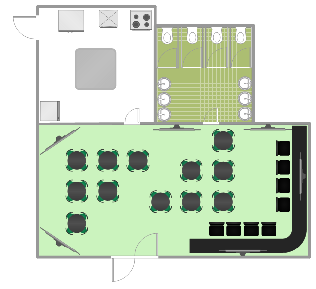
How To Create Restaurant Floor Plan in Minutes
Developing Floor Plans, Design Drawings, Plans of Furniture Placement for restaurants and cafes is one of the most responsible and important steps at their construction and designing. Selection of favorable design, the right style of furniture and decors largely determine the success and atmosphere of the institution. The restaurant floor planner ConceptDraw PRO is a perfect choice for architects and designers. Enhanced with Cafe and Restaurant Floor Plans solution it offers a lot of extensive vector symbol libraries and building plan elements for drawing Restaurant floor plans, Restaurant layouts, Restaurant furniture layouts, Cafe floor plans, Bar area floor plan, Fast food restaurant plan, etc. With ConceptDraw PRO you don't need to be an artist to create great-looking restaurant floor plan drawings in minutes, all needed drawing tools are delivered by Building Plans area solutions. Construct your own general plan of restaurant's premises, choose the furniture for your taste from the Cafe and Restaurant Floor Plans solution libraries and arrange it on the plan as you desire fast and easy. ConceptDraw PRO has many of the features found in Visio for Mac such as Drawing, Connection, Shape and Editing Tools.
Bubble diagrams in Landscape Design with ConceptDraw PRO
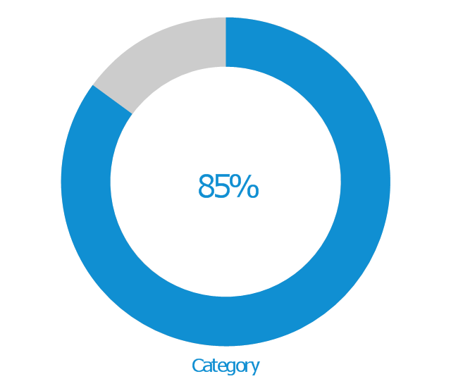
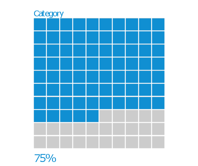
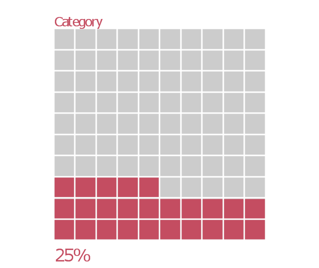
Bubble Diagrams are the charts with a bubble presentation of data with obligatory consideration of bubble's sizes. They are analogs of Mind Maps and find their application at many fields, and even in landscape design. At this case the bubbles are applied to illustrate the arrangement of different areas of future landscape design, such as lawns, flowerbeds, playgrounds, pools, recreation areas, etc. Bubble Diagram helps to see instantly the whole project, it is easy for design and quite informative, in most cases it reflects all needed information. Often Bubble Diagram is used as a draft for the future landscape project, on the first stage of its design, and in case of approval of chosen design concept is created advanced detailed landscape plan with specification of plants and used materials. Creation of Bubble Diagrams for landscape in ConceptDraw PRO software is an easy task thanks to the Bubble Diagrams solution from "Diagrams" area. You can use the ready scanned location plan as the base or create it easy using the special ConceptDraw libraries and templates.The vector stencils library "Management indicators" contains 14 visual indicators.
Use it to create your management infogram in the ConceptDraw PRO diagramming and vector drawing software.
The example "Management indicators - Vector stencils library" is included in the solution "Marketing infographics" from the "Business infographics" area of ConceptDraw Solution Park.
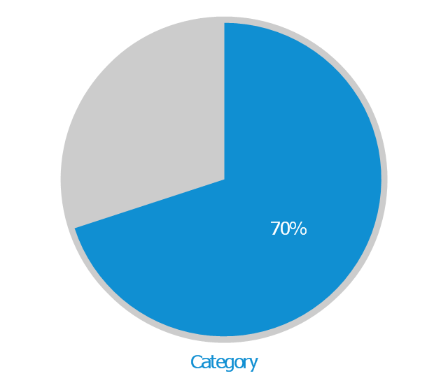
Use it to create your management infogram in the ConceptDraw PRO diagramming and vector drawing software.
The example "Management indicators - Vector stencils library" is included in the solution "Marketing infographics" from the "Business infographics" area of ConceptDraw Solution Park.
HelpDesk
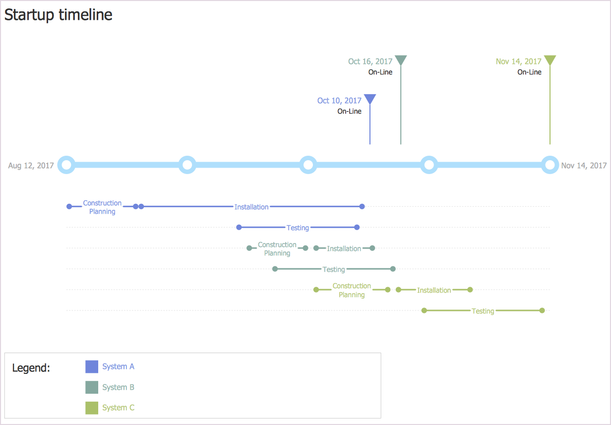
How to Create a Timeline Diagram in ConceptDraw PRO
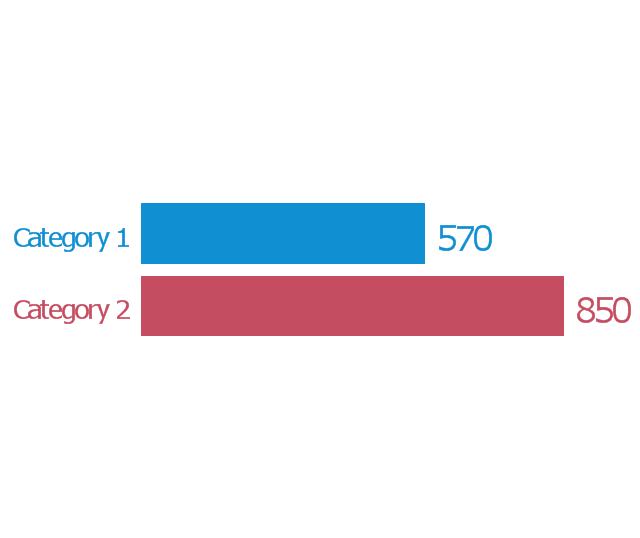
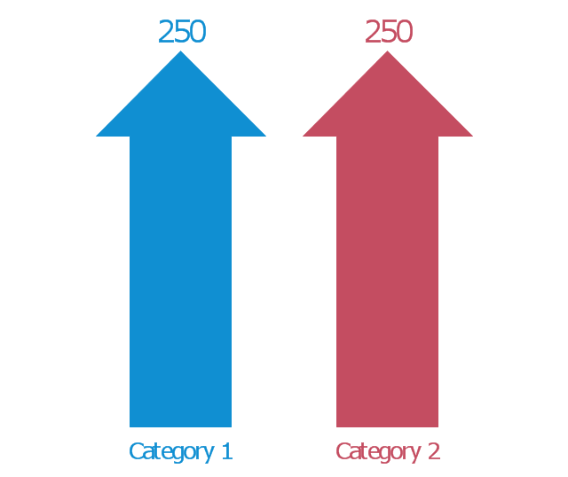
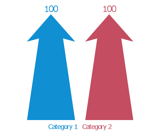
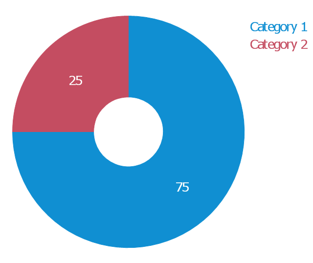
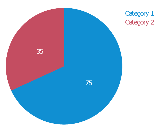
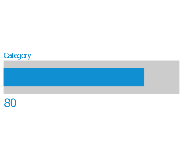
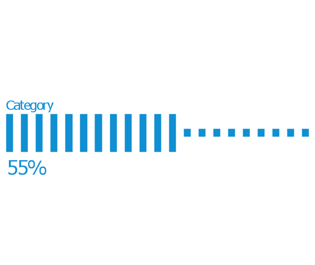
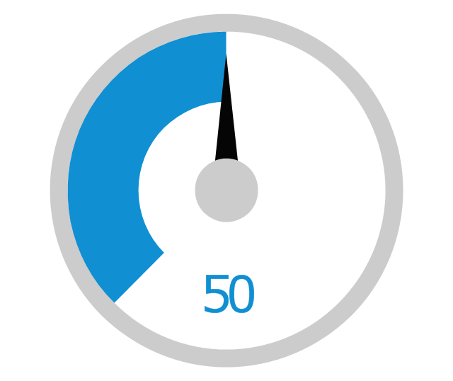
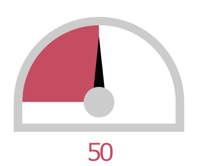
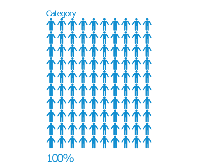
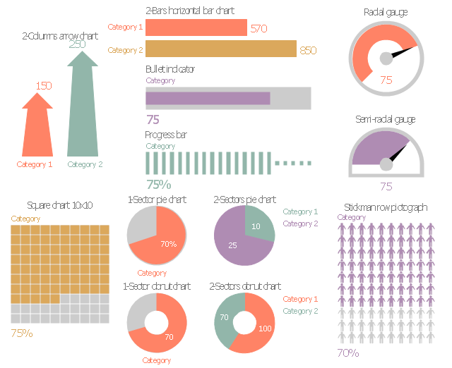
A Timeline is a chart which displays a project plan schedule in chronological order. A Timeline is used in project management to depict project milestones and visualize project phases, and show project progress. The graphic form of a timeline makes it easy to understand critical project milestones, such as the progress of a project schedule. Timelines are particularly useful for project scheduling or project management when accompanied with a Gantt chart. It captures the main of what the project will accomplish and how it will be done. making a project timeline is one of the most important skills a project manager needs have. Making comprehensive, accurate timelines allows you getting every project off in the best way. ConceptDraw PRO allows you to draw a timeline charts using special library.The vector stencils library "Marketing indicators" contains 12 graphic indicators: horizontal bar chart, pie chart, arrow chart, donut chart, square chart, stickman row pictograph, progress bar, bullet indicator, radial gauge, semi-radial gauge.
Use these visual indicators to design your marketing infograms.
The shapes example "Design elements - Marketing indicators" was created using the ConceptDraw PRO diagramming and vector drawing software extended with the Marketing Infographics solition from the area "Business Infographics" in ConceptDraw Solution Park.
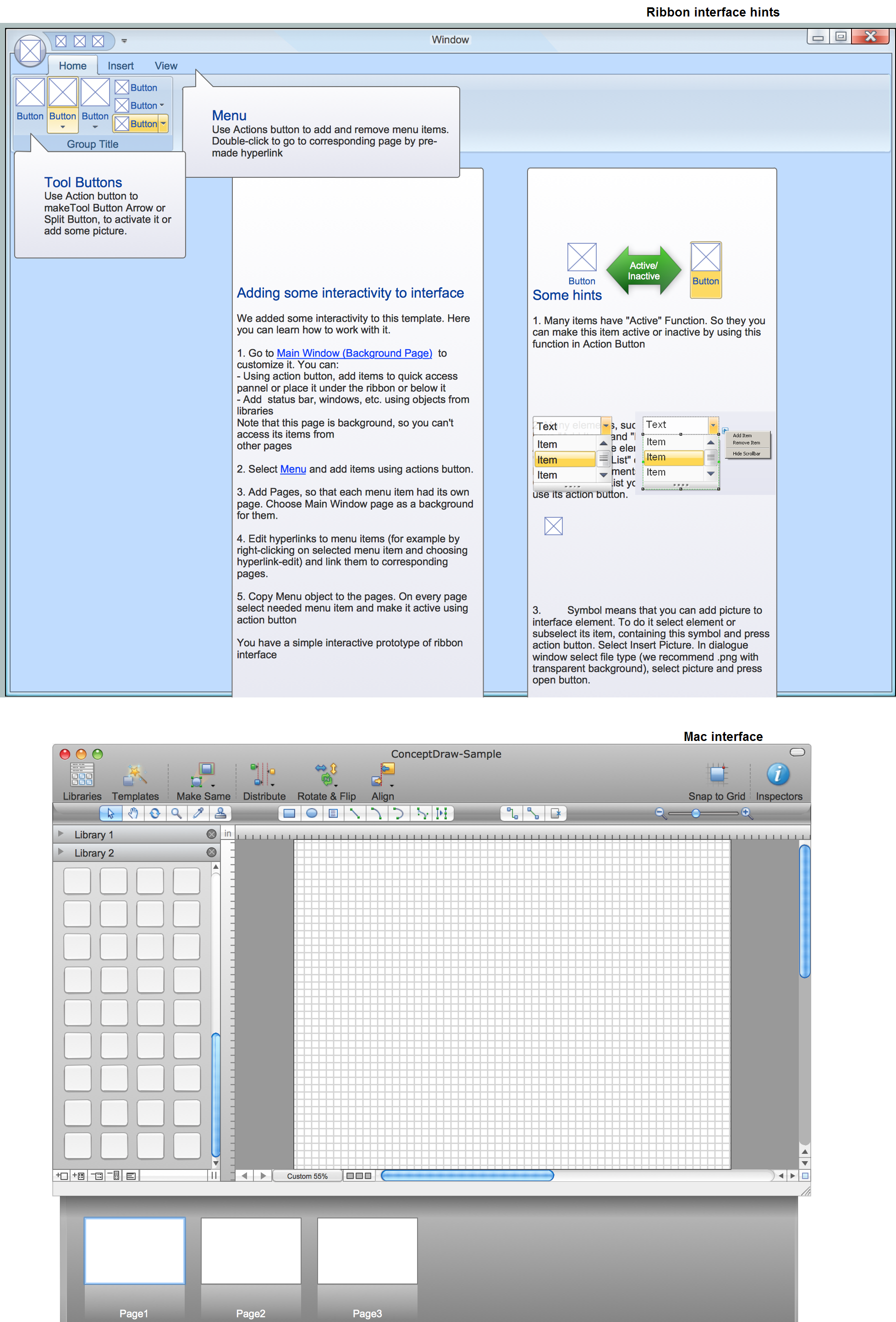
GUI Prototyping with ConceptDraw PRO
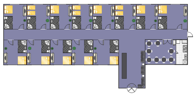
All about prototyping. GUI Prototyping with ConceptDraw. Download prototyping software.This example depicts furniture and home appliances layout on the hotel floor plan.
"A hotel is an establishment that provides lodging paid on a short-term basis. The provision of basic accommodation, in times past, consisting only of a room with a bed, a cupboard, a small table and a washstand has largely been replaced by rooms with modern facilities, including en-suite bathrooms and air conditioning or climate control. Additional common features found in hotel rooms are a telephone, an alarm clock, a television, a safe, a mini-bar with snack foods and drinks, and facilities for making tea and coffee. Luxury features include bathrobes and slippers, a pillow menu, twin-sink vanities, and jacuzzi bathtubs. Larger hotels may provide additional guest facilities such as a swimming pool, fitness center, business center, childcare, conference facilities and social function services." [Hotel. Wikipedia]
The example "Hotel floor plan" was created using the ConceptDraw PRO diagramming and vector drawing software extended with the Floor Plans solution from the Building Plans area of ConceptDraw Solution Park.
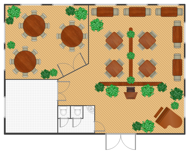
The Restaurant plan example shows furniture layout in the restaurant.
"Restaurants may be classified or distinguished in many different ways. The primary factors are usually the food itself (e.g. vegetarian, seafood, steak); the cuisine (e.g. Italian, Chinese, Indian, French, Thai) and/ or the style of offering (e.g. tapas bar, a sushi train, a tastet restaurant, a buffet restaurant or a yum cha restaurant). Beyond this, restaurants may differentiate themselves on factors including speed (see fast food), formality, location, cost, service, or novelty themes (such as automated restaurants).
Restaurants range from inexpensive and informal lunching or dining places catering to people working nearby, with simple food served in simple settings at low prices, to expensive establishments serving refined food and fine wines in a formal setting. In the former case, customers usually wear casual clothing. In the latter case, depending on culture and local traditions, customers might wear semi-casual, semi-formal or formal wear. Typically, customers sit at tables, their orders are taken by a waiter, who brings the food when it is ready. After eating, the customers then pay the bill." [Restaurant. Wikipedia]
The Restaurant plan example was created using ConceptDraw PRO diagramming and vector drawing software extended with the Cafe and Restaurant solution from Building Plans area of ConceptDraw Solution Park.
 Landscape & Garden
The Landscape and Gardens solution for ConceptDraw PRO v10 is the ideal drawing tool when creating landscape plans. Any gardener wondering how to design a garden can find the most effective way with Landscape and Gardens solution.
Geo Map - Asia - Philippines
The Philippines, officially known as the Republic of the Philippines, is a sovereign island country in Southeast Asia situated in the western Pacific Ocean. Use the Continent Maps solution and Philippines library to draw thematic maps, geospatial infographics and vector illustrations. This solution to help visualize the business and thematic information connected with geographic areas, locations or customs; for your business documents, presentations and websites.
 Floor Plans
Construction, repair and remodeling of the home, flat, office, or any other building or premise begins with the development of detailed building plan and floor plans. Correct and quick visualization of the building ideas is important for further construction of any building.
The Data flow diagram (DFD) example "Payment for goods using UPS code scanner" shows data flow in process of payment for goods in the shop using the MaxiCode scanner.
"MaxiCode is a public domain, machine-readable symbol system originally created and used by United Parcel Service. Suitable for tracking and managing the shipment of packages, it resembles a barcode, but uses dots arranged in a hexagonal grid instead of bars. MaxiCode has been standardised under ISO/ IEC 16023.
A MaxiCode symbol (internally called "Bird's Eye", "Target", "dense code", or "UPS code") appears as a 1 inch square, with a bullseye in the middle, surrounded by a pattern of hexagonal dots. It can store about 93 characters of information, and up to 8 MaxiCode symbols can be chained together to convey more data. The centered symmetrical bullseye is useful in automatic symbol location regardless of orientation, and it allows MaxiCode symbols to be scanned even on a package traveling rapidly." [MaxiCode. Wikipedia]
This example of data flow diagram (Gane & Sarson notation) was created using the ConceptDraw PRO diagramming and vector drawing software extended with the Data Flow Diagrams solution from the Software Development area of ConceptDraw Solution Park.
 Mechanical Engineering
This solution extends ConceptDraw PRO v.9 mechanical drawing software (or later) with samples of mechanical drawing symbols, templates and libraries of design elements, for help when drafting mechanical engineering drawings, or parts, assembly, pneumatic,
"Bars categorized by the kind of entertainment they offer include:
(1) Blues bars, specializing in the live blues style of music.
(2) Comedy Bar specializing in a stand-up comedy entertainment.
(3) Dance bars, which have a dance floor where patrons dance to recorded music.
(4) But if a dance bar has a large dance floor and hires well-known professional DJs, it is considered to be a nightclub or discothèque.
(5) Karaoke bars, with nightly karaoke as entertainment.
(6) Music bars, specializing in live music (i.e. concerts).
(7) Drag bars, which have live shows, where men dress as women and generally lip-sync to recordings of female vocal artists; often with hilarious results.
(8) Salsa bars, where patrons dance to Latin salsa music.
(9) Sports bars, where sports fans watch games on large-screen televisions.
(10) Topless bars, where topless female employees dance or serve drinks." [Bar (establishment). Wikipedia]
The floor plan example "Sports bar" was created using the ConceptDraw PRO diagramming and vector drawing software extended with the Cafe and Restaurant solution from the Building Plans area of ConceptDraw Solution Park.
- Salad Bar Floor Plan
- Visualize Sales Data Using Sample Data
- How to Connect Tabular Data (CSV) to a Graphic Indicator on Your ...
- Plan Of Bar Counter Design
- Arrows Bar Chart
- Mini Hotel Floor Plan. Floor Plan Examples | Hotel Floorplan | Hotel ...
- Sports bar - Floor plan | Home network plan | Design elements ...
- Floor Plan For A Toilet Designed For A Bar
- Picture graphs - Vector stencils library | Management indicators ...
- Management indicators - Vector stencils library | Education ...
- Basic Flowchart Symbols and Meaning | Basic Diagramming | Bar ...
- Restaurant Layout In A Square
- Salad Bar
- Fast casual restaurant floor plan | Design elements - Cafe and ...
- Design elements - Cafe and restaurant | Restaurant plan ...
- Area Graph Example
- Management indicators - Vector stencils library | Education ...
- Management indicators - Vector stencils library | Education ...
- Management indicators - Vector stencils library | Management ...
- Restaurant Bar Counter Drawings



---payment-for-goods-using-ups-code-scanner.png--diagram-flowchart-example.png)
