HelpDesk
How to Create a Timeline Diagram

This engineering drawing present weld type symbols and fillet weld symbols.
The weld type symbol is typically placed above or below the center of the reference line, depending on which side of the joint it's on. The symbol is interpreted as a simplified cross-section of the weld.
"Fillet welding refers to the process of joining two pieces of metal together whether they be perpendicular or at an angle. These welds are commonly referred to as Tee joints which are two pieces of metal perpendicular to each other or Lap joints which are two pieces of metal that overlap and are welded at the edges. The weld is aesthetically triangular in shape and may have a concave, flat or convex surface depending on the welder’s technique. Welders use fillet welds when connecting flanges to pipes, welding cross sections of infrastructure, and when fastening metal by bolts isn't strong enough." [Fillet weld. Wikipedia]
The engineering drawing example Welding symbols is included in the Mechanical Engineering solution from Engineering area of ConceptDraw Solution Park.
Welding joint symbols

The vector stencils library "HR flowchart" contains 62 flowchart symbols.
Use it to draw your HR flowcharts, workflow diagrams and process charts with the ConceptDraw PRO diagramming and vector drawing software.
The flow chart symbols library "HR flowchart" is included in the HR Flowcharts solution from the Management area of ConceptDraw Solution Park.
Use it to draw your HR flowcharts, workflow diagrams and process charts with the ConceptDraw PRO diagramming and vector drawing software.
The flow chart symbols library "HR flowchart" is included in the HR Flowcharts solution from the Management area of ConceptDraw Solution Park.
Annotation
Card

Check / audit (diamond)
-hr-flowchart---vector-stencils-library.png--diagram-flowchart-example.png)
Check / audit (square)
-hr-flowchart---vector-stencils-library.png--diagram-flowchart-example.png)
Collate

Comment / note symbol (brace)
-hr-flowchart---vector-stencils-library.png--diagram-flowchart-example.png)
Communication link
Compare (diamond)
-hr-flowchart---vector-stencils-library.png--diagram-flowchart-example.png)
Compare (square)
-hr-flowchart---vector-stencils-library.png--diagram-flowchart-example.png)
Completed form

Concurrency symbol (fork / join)
-hr-flowchart---vector-stencils-library.png--diagram-flowchart-example.png)
Conditional selector
Control transfer

Data input / output

Database
Decision

Decision indicator - No
Decision indicator - Yes
Delay

Direct access storage

Disk storage
Display

Divided process (table view)
-hr-flowchart---vector-stencils-library.png--diagram-flowchart-example.png)
Document

Entity (rounded)
-hr-flowchart---vector-stencils-library.png--diagram-flowchart-example.png)
Event

Extract
Flow line
Internal storage

Junction symbol

Lined document

Lined / shaded process

Loop limit

Manual file
Manual input

Manual operation

Merge
Multi document

Multi process

Off-page reference - arrow
Off-page reference - incoming

Off-page reference - outgoing

On-page reference/ Inspection point
Or
Page

Paper tape

Predefined process

Prepare conditional

Process step

Reference point

Sequential access storage

Sort
Start (circle)
-hr-flowchart---vector-stencils-library.png--diagram-flowchart-example.png)
Start (ellipse)
-hr-flowchart---vector-stencils-library.png--diagram-flowchart-example.png)
Stickman pictogram

Stored data

Summary
Tagged document

Tagged process

Terminal point
Title block
Torso pictogram

The vector stencils library "Sales flowchart" contains 62 sales process flow chart symbols.
Use these flow chart icon set to draw your sales flowcharts, workflow diagrams and process charts with the ConceptDraw PRO diagramming and vector drawing software.
The sales process flowchart symbols library "Sales flowchart" is included in the Sales Flowcharts solution from the Marketing area of ConceptDraw Solution Park.
Annotation
Card

Check / audit (diamond)
-sales-flowchart---vector-stencils-library.png--diagram-flowchart-example.png)
Check / audit (square)
-sales-flowchart---vector-stencils-library.png--diagram-flowchart-example.png)
Collate

Comment / note symbol (brace)
-sales-flowchart---vector-stencils-library.png--diagram-flowchart-example.png)
Communication link

Compare (diamond)
-sales-flowchart---vector-stencils-library.png--diagram-flowchart-example.png)
Compare (square)
-sales-flowchart---vector-stencils-library.png--diagram-flowchart-example.png)
Completed form

Concurrency symbol (fork / join)
-sales-flowchart---vector-stencils-library.png--diagram-flowchart-example.png)
Conditional selector
Control transfer
Database
Data input / output

Decision

Decision indicator - No
Decision indicator - Yes
Delay

Direct access storage

Disk storage
Display

Divided process (table view)
-sales-flowchart---vector-stencils-library.png--diagram-flowchart-example.png)
Document

Entity (rounded)
-sales-flowchart---vector-stencils-library.png--diagram-flowchart-example.png)
Event

Extract
Flow line
Internal storage

Junction symbol

Lined document

Lined / shaded process

Loop limit

Manual file
Manual input

Manual operation

Merge
Multi document

Multi process

Off-page reference - arrow
Off-page reference - incoming

Off-page reference - outgoing

On-page reference/ Inspection point

Or
Page

Paper tape

Predefined process

Prepare conditional

Process step

Reference point

Sequential access storage

Sort
Start (circle)
-sales-flowchart---vector-stencils-library.png--diagram-flowchart-example.png)
Start (ellipse)
-sales-flowchart---vector-stencils-library.png--diagram-flowchart-example.png)
Stickman pictogram

Stored data

Summary
Tagged document

Tagged process

Terminal point

Title block

Torso pictogram

HelpDesk
How to Set Line Jumps for Smart Connectors in ConceptDraw DIAGRAM

Bubble diagrams in Landscape Design with ConceptDraw DIAGRAM

"Directional control valves are one of the most fundamental parts in hydraulic machinery as well and pneumatic machinery. They allow fluid flow into different paths from one or more sources. They usually consist of a spool inside a cylinder which is mechanically or electrically controlled. The movement of the spool restricts or permits the flow, thus it controls the fluid flow. ...
While working with layouts of hydraulic machinery it is cumbersome to draw actual picture of every valve and other components.instead of pictures symbols are used for variety of components in the hydraulic system to highlight the functional aspects. symbol for directional control valve is made of number of square boxes adjacent to each other depending on the number of positions.connections to the valve are shown on these squares by capital letters.usually they are named only in their normal position and not repeated in other positions.actuation system of the valve is also designated in its symbol." [Directional control valve. Wikipedia]
The Mac template "Pneumatic 5-ported 3-position valve" for the ConceptDraw PRO diagramming and vector drawing software is included in the Mechanical Engineering solution from the Engineering area of ConceptDraw Solution Park.
www.conceptdraw.com/ solution-park/ engineering-mechanical
Pneumatic directional control valve

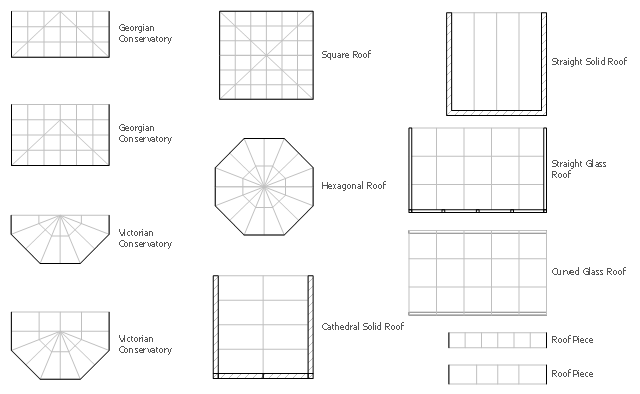
The design elements library Sunrooms contains 12 symbols of glass roof and conservatory.
Use the vector stencils library Sunrooms to draw the sunroom design plans, home layouts, architectural and construction documents.
"A sunroom, sun parlor, sun porch, or sun lounge is a structure usually constructed onto the side of a house which allows enjoyment of the surrounding landscape while being sheltered from adverse weather conditions such as rain and wind. It can be referred to as a patio room, solarium, conservatory or Florida room. The concept is popular in the United States, Europe, Canada, Australia, and New Zealand.
In Great Britain, the term conservatory is usually used to refer to a sunroom despite not being used as a greenhouse as traditional conservatories were. However, sunrooms with opaque roofs may be considered distinct from conservatories with transparent or semi-transparent roofs." [Sunroom. Wikipedia]
The shapes library Sunrooms is provided by the Floor Plans solution from the Building Plans area of ConceptDraw Solution Park.
 Mechanical Engineering
This solution extends ConceptDraw DIAGRAM.9 mechanical drawing software (or later) with samples of mechanical drawing symbols, templates and libraries of design elements, for help when drafting mechanical engineering drawings, or parts, assembly, pneumatic,
IDEF4 Standard

- Symbol Of Square Pipe Section In Engineering Drawing
- Mechanical Drawing Symbols | Mechanical Engineering ...
- Welding Symbols On Drawings
- Elements location of a welding symbol | Mechanical Engineering ...
- How To use Furniture Symbols for Drawing Building Plan | Cafe and ...
- Drawing Symbol Of Bevel Joint
- Welding symbols | Mechanical Drawing Symbols | Design elements ...
- How To use Furniture Symbols for Drawing Building Plan | Design ...
- Mechanical Drawing Symbols | Welding symbols | Elements location ...
- How To use Furniture Symbols for Drawing Building Plan | Building ...
- Mechanical Drawing Symbols | Electrical Symbols — Rotating ...
- Mechanical Drawing Symbols | UML Flowchart Symbols | Design ...
- How To use Furniture Symbols for Drawing Building Plan | Design ...
- How To use Furniture Symbols for Drawing Building Plan | Building ...
- Symbol For Joints In Drawing
- Butt weld geometry | Mechanical Engineering | Welding symbols ...
- Drawing Of Welding Joints
- Welding symbols | Mechanical Drawing Symbols | Elements location ...
- Butt weld geometry | Welding symbols | Welded joints types | Weld ...
- Mechanical Engineering | Mechanical Drawing Symbols | Welding ...