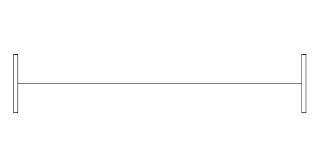
The vector stencils library "Windows" contains 34 window shapes.
Use it for drawing floor plans in the ConceptDraw PRO diagramming and vector drawing software extended with the Floor Plans solution from the Building Plans area of ConceptDraw Solution Park.
www.conceptdraw.com/ solution-park/ floor-plans
Use it for drawing floor plans in the ConceptDraw PRO diagramming and vector drawing software extended with the Floor Plans solution from the Building Plans area of ConceptDraw Solution Park.
www.conceptdraw.com/ solution-park/ floor-plans
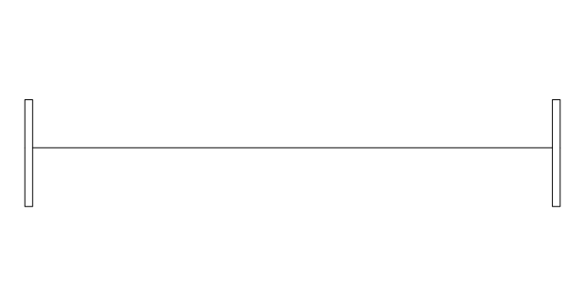
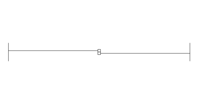
Window
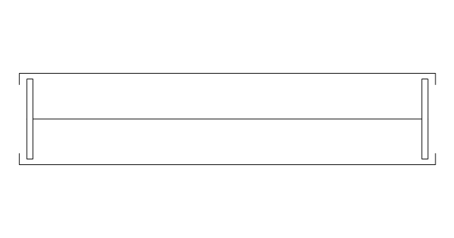
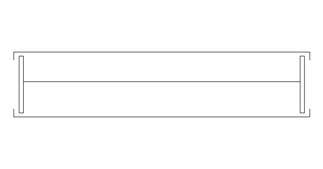
Window, sill
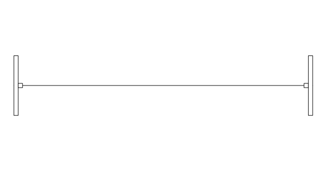
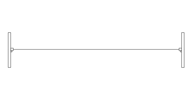
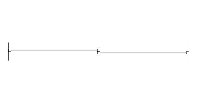
Window, sash
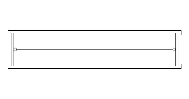
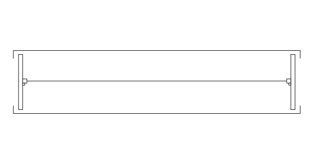
Window, sash, sill
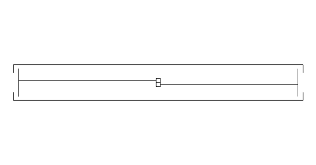
Window, frame
Window, frame, sill
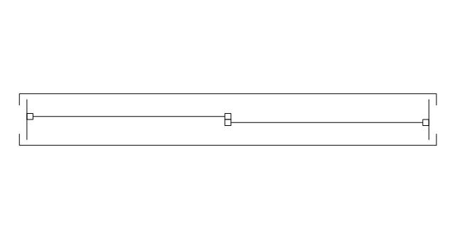
Window, frame, sash
Window, frame, sash, sill
Glider window
Glider window, sill
Glider window, sash
Glider window, sash, sill
Glider window, frame
Glider window, frame, sill
Glider window, frame, sash
Glider window, frame, sash, sill
Garden window
Garden window, sill
Garden window, sash
Garden window, sash, sill
Garden window, frame
Garden window, frame, sash
Garden window, frame, sill
Garden window, frame, sash, sill
Bay window

Bow window
Casement

Casement, sill
Casement, sash
Casement, sash, sill
Casement, frame
Casement, frame, sill
Casement, frame, sash
Casement, frame, sash, sill
The vector stencils library "Windows" contains 34 window shapes.
Use it for drawing floor plans in the ConceptDraw PRO diagramming and vector drawing software extended with the Floor Plans solution from the Building Plans area of ConceptDraw Solution Park.
www.conceptdraw.com/ solution-park/ floor-plans
Use it for drawing floor plans in the ConceptDraw PRO diagramming and vector drawing software extended with the Floor Plans solution from the Building Plans area of ConceptDraw Solution Park.
www.conceptdraw.com/ solution-park/ floor-plans
Window
Window, sill
Window, sash
Window, sash, sill
Window, frame
Window, frame, sill
Window, frame, sash
Window, frame, sash, sill
Glider window
Glider window, sill
Glider window, sash
Glider window, sash, sill
Glider window, frame
Glider window, frame, sill
Glider window, frame, sash
Glider window, frame, sash, sill
Garden window
Garden window, sill
Garden window, sash
Garden window, sash, sill
Garden window, frame
Garden window, frame, sash
Garden window, frame, sill
Garden window, frame, sash, sill
Bay window
Bow window
Casement
Casement, sill
Casement, sash
Casement, sash, sill
Casement, frame
Casement, frame, sill
Casement, frame, sash
Casement, frame, sash, sill
The vector stencils library "Network layout floorplan" contain 34 symbol icons for drawing computer network floor plans, communication equipment layouts, and structured cabling diagrams.
"Structured cabling is building or campus telecommunications cabling infrastructure that consists of a number of standardized smaller elements (hence structured) called subsystems. ...
Structured cabling design and installation is governed by a set of standards that specify wiring data centers, offices, and apartment buildings for data or voice communications using various kinds of cable, most commonly category 5e (CAT-5e), category 6 (CAT-6), and fibre optic cabling and modular connectors. These standards define how to lay the cabling in various topologies in order to meet the needs of the customer, typically using a central patch panel (which is normally 19 inch rack-mounted), from where each modular connection can be used as needed. Each outlet is then patched into a network switch (normally also rack-mounted) for network use or into an IP or PBX (private branch exchange) telephone system patch panel." [Structured cabling. Wikipedia]
The design elements example "Network layout floorplan - Vector stencils library" was created using the ConceptDraw PRO diagramming and vector drawing software extended with the Network Layout Floor Plans solution from the Computer and Networks area of ConceptDraw Solution Park.
PC

Scanner

Switch

Router

Modem

Hub

Rack Mount

Printer

Floor Mounted Outlet

Single Outlet

Duplex Outlet

Direct bus cable

Tops or bottoms bus cable

Side to side bus cable

Multi-tree bus cable

Bottom to side bus cable

Sides bus cable

Door

Door, threshold

Door, stop

Door, stop, threshold

Door, frame

Door, frame, threshold

Door, frame, stop

Door, frame, stop, threshold

Window

Window, sill

Window, sash

Window, sash, sill

Window, frame

Window, frame, sill

Window, frame, sash

Window, frame, sash, sill

The vector stencils library "Windows" contains 34 window shapes.
Use it for drawing floor plans in the ConceptDraw PRO diagramming and vector drawing software extended with the Floor Plans solution from the Building Plans area of ConceptDraw Solution Park.
www.conceptdraw.com/ solution-park/ floor-plans
Use it for drawing floor plans in the ConceptDraw PRO diagramming and vector drawing software extended with the Floor Plans solution from the Building Plans area of ConceptDraw Solution Park.
www.conceptdraw.com/ solution-park/ floor-plans
Window
Window, sill
Window, sash
Window, sash, sill
Window, frame
Window, frame, sill
Window, frame, sash
Window, frame, sash, sill
Glider window
Glider window, sill
Glider window, sash
Glider window, sash, sill
Glider window, frame
Glider window, frame, sill
Glider window, frame, sash
Glider window, frame, sash, sill
Garden window
Garden window, sill
Garden window, sash
Garden window, sash, sill
Garden window, frame
Garden window, frame, sash
Garden window, frame, sill
Garden window, frame, sash, sill
Bay window
Bow window
Casement
Casement, sill
Casement, sash
Casement, sash, sill
Casement, frame
Casement, frame, sill
Casement, frame, sash
Casement, frame, sash, sill
The vector stencils library "Network layout floorplan" contain 34 symbol icons for drawing computer network floor plans, communication equipment layouts, and structured cabling diagrams.
"Structured cabling is building or campus telecommunications cabling infrastructure that consists of a number of standardized smaller elements (hence structured) called subsystems. ...
Structured cabling design and installation is governed by a set of standards that specify wiring data centers, offices, and apartment buildings for data or voice communications using various kinds of cable, most commonly category 5e (CAT-5e), category 6 (CAT-6), and fibre optic cabling and modular connectors. These standards define how to lay the cabling in various topologies in order to meet the needs of the customer, typically using a central patch panel (which is normally 19 inch rack-mounted), from where each modular connection can be used as needed. Each outlet is then patched into a network switch (normally also rack-mounted) for network use or into an IP or PBX (private branch exchange) telephone system patch panel." [Structured cabling. Wikipedia]
The design elements example "Network layout floorplan - Vector stencils library" was created using the ConceptDraw PRO diagramming and vector drawing software extended with the Network Layout Floor Plans solution from the Computer and Networks area of ConceptDraw Solution Park.
"Structured cabling is building or campus telecommunications cabling infrastructure that consists of a number of standardized smaller elements (hence structured) called subsystems. ...
Structured cabling design and installation is governed by a set of standards that specify wiring data centers, offices, and apartment buildings for data or voice communications using various kinds of cable, most commonly category 5e (CAT-5e), category 6 (CAT-6), and fibre optic cabling and modular connectors. These standards define how to lay the cabling in various topologies in order to meet the needs of the customer, typically using a central patch panel (which is normally 19 inch rack-mounted), from where each modular connection can be used as needed. Each outlet is then patched into a network switch (normally also rack-mounted) for network use or into an IP or PBX (private branch exchange) telephone system patch panel." [Structured cabling. Wikipedia]
The design elements example "Network layout floorplan - Vector stencils library" was created using the ConceptDraw PRO diagramming and vector drawing software extended with the Network Layout Floor Plans solution from the Computer and Networks area of ConceptDraw Solution Park.
PC
Scanner
Switch
Router
Modem
Hub
Rack Mount
Printer
Floor Mounted Outlet
Single Outlet
Duplex Outlet
Direct bus cable
Tops or bottoms bus cable
Side to side bus cable
Multi-tree bus cable
Bottom to side bus cable
Sides bus cable
Door
Door, threshold
Door, stop
Door, stop, threshold
Door, frame
Door, frame, threshold
Door, frame, stop
Door, frame, stop, threshold
Window
Window, sill
Window, sash
Window, sash, sill
Window, frame
Window, frame, sill
Window, frame, sash
Window, frame, sash, sill
- Windows - Vector stencils library
- Glider window , sash
- Garden window , sash
- Glider window , frame, sash
- Windows - Vector stencils library
- Window , frame, sash
- Windows - Vector stencils library | Windows - Vector stencils library ...
- Windows - Vector stencils library
- Windows - Vector stencils library | How to Plan and Allocate ...
- Windows - Vector stencils library
- Windows - Vector stencils library
- Windows - Vector stencils library | Windows 8 apps - Vector stencils ...
- Windows - Vector stencils library
- Window , sash
- Window , sash , sill
- Window , frame, sash
- Window , frame, sash , sill
- Window elements - Vector stencils library | Design elements ...
- Network layout floorplan - Vector stencils library
- Network layout floorplan - Vector stencils library
- ERD | Entity Relationship Diagrams, ERD Software for Mac and Win
- Flowchart | Basic Flowchart Symbols and Meaning
- Flowchart | Flowchart Design - Symbols, Shapes, Stencils and Icons
- Flowchart | Flow Chart Symbols
- Electrical | Electrical Drawing - Wiring and Circuits Schematics
- Flowchart | Common Flowchart Symbols
- Flowchart | Common Flowchart Symbols