The vector stencils library "Switches" contains 25 symbols of electrical and light switches and breakers.
"In electrical engineering, a switch is an electrical component that can break an electrical circuit, interrupting the current or diverting it from one conductor to another.
The most familiar form of switch is a manually operated electromechanical device with one or more sets of electrical contacts, which are connected to external circuits.
A switch may be directly manipulated by a human as a control signal to a system, ... or to control power flow in a circuit, such as a light switch. Automatically operated switches can be used to control the motions of machines, for example, to indicate that a garage door has reached its full open position or that a machine tool is in a position to accept another workpiece. Switches may be operated by process variables such as pressure, temperature, flow, current, voltage, and force, acting as sensors in a process and used to automatically control a system. For example, a thermostat is a temperature-operated switch used to control a heating process. A switch that is operated by another electrical circuit is called a relay." [Switch. Wikipedia]
Use the design elements library "Switches" for drawing light switches layouts, electrical and telecommunication equipment floor plans for building design and construction using the ConceptDraw PRO diagramming and vector drawing software.
The shapes library "Switches" is included in the Electric and Telecom Plans solution from the Building Plans area of ConceptDraw Solution Park.
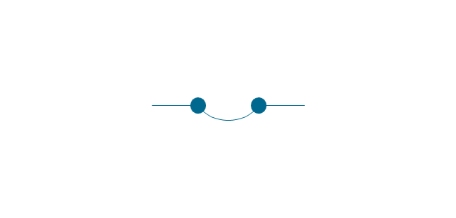
The vector stencils library "Switches and relays" contains 58 symbols of electrical contacts, switches, relays, circuit breakers, selectors, connectors, disconnect devices, switching circuits, current regulators, and thermostats for electrical devices.
"In electrical engineering, a switch is an electrical component that can break an electrical circuit, interrupting the current or diverting it from one conductor to another.
The most familiar form of switch is a manually operated electromechanical device with one or more sets of electrical contacts, which are connected to external circuits. Each set of contacts can be in one of two states: either "closed" meaning the contacts are touching and electricity can flow between them, or "open", meaning the contacts are separated and the switch is nonconducting. The mechanism actuating the transition between these two states (open or closed) can be either a "toggle" (flip switch for continuous "on" or "off") or "momentary" (push-for "on" or push-for "off") type.
A switch may be directly manipulated by a human as a control signal to a system, such as a computer keyboard button, or to control power flow in a circuit, such as a light switch. Automatically operated switches can be used to control the motions of machines, for example, to indicate that a garage door has reached its full open position or that a machine tool is in a position to accept another workpiece. Switches may be operated by process variables such as pressure, temperature, flow, current, voltage, and force, acting as sensors in a process and used to automatically control a system. ... A switch that is operated by another electrical circuit is called a relay. Large switches may be remotely operated by a motor drive mechanism. Some switches are used to isolate electric power from a system, providing a visible point of isolation that can be padlocked if necessary to prevent accidental operation of a machine during maintenance, or to prevent electric shock." [Switch. Wikipedia]
"A relay is an electrically operated switch. Many relays use an electromagnet to mechanically operate a switch, but other operating principles are also used, such as solid-state relays. Relays are used where it is necessary to control a circuit by a low-power signal (with complete electrical isolation between control and controlled circuits), or where several circuits must be controlled by one signal. The first relays were used in long distance telegraph circuits as amplifiers: they repeated the signal coming in from one circuit and re-transmitted it on another circuit. Relays were used extensively in telephone exchanges and early computers to perform logical operations.
A type of relay that can handle the high power required to directly control an electric motor or other loads is called a contactor. Solid-state relays control power circuits with no moving parts, instead using a semiconductor device to perform switching. Relays with calibrated operating characteristics and sometimes multiple operating coils are used to protect electrical circuits from overload or faults; in modern electric power systems these functions are performed by digital instruments still called "protective relays"." [Relay. Wikipedia]
The shapes example "Design elements - Switches and relays" was drawn using the ConceptDraw PRO diagramming and vector drawing software extended with the Electrical Engineering solution from the Engineering area of ConceptDraw Solution Park.
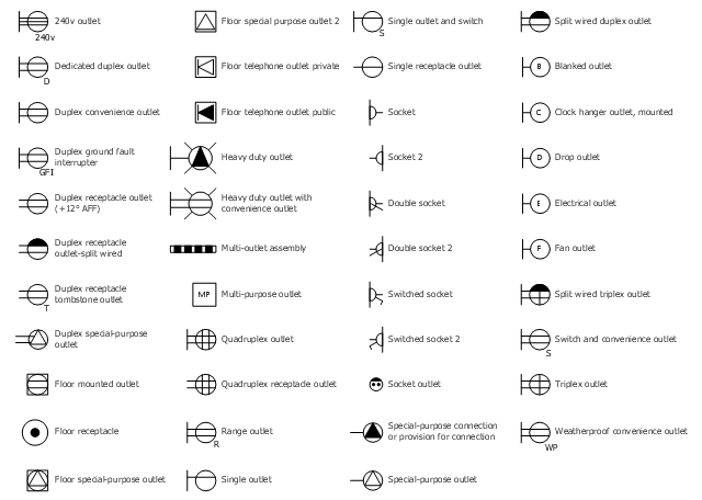
The vector stencil library "RCP-Electrical outlets" contains 43 socket symbols.
Use it to design your reflected ceiling plan with ConceptDraw DIAGRAM software.
"An electrical outlet or receptacle is a socket that connects an electrical device to an electricity supply. In buildings, electrical outlets are usually installed in the wall, although they can also be installed in the floor. Occasionally, they are found in the ceiling for powering devices such as garage door openers or neon signs in storefront windows. Different countries often have different outlet types and voltages. Adapters are available to convert between the different types." [Electrical outlet. Simple Wikipedia]
The receptacle symbols example "Design Elements - RCP-Electrical outlets" is included in Reflected Ceiling Plans solution from the Building Plans area of ConceptDraw Solution Park.
Mechanical Drawing Symbols
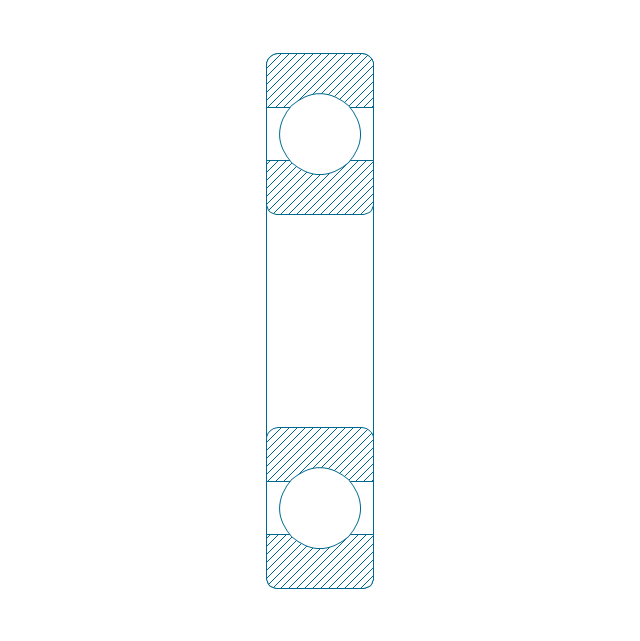
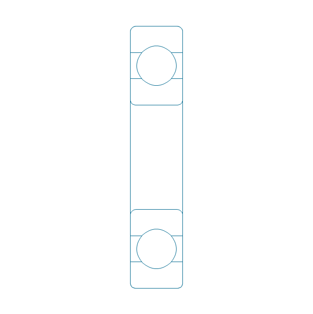
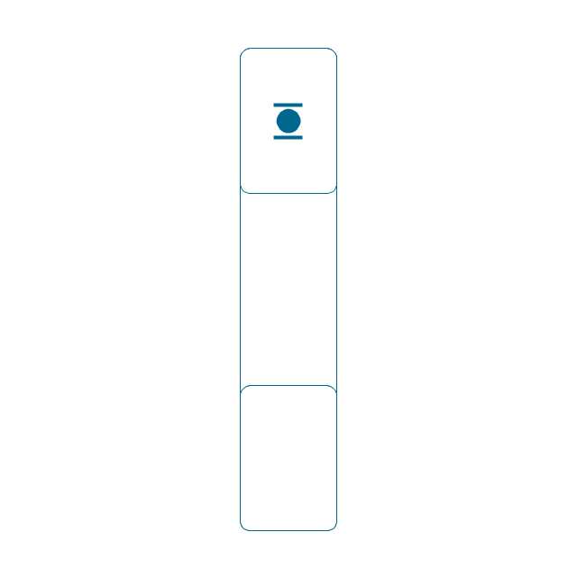
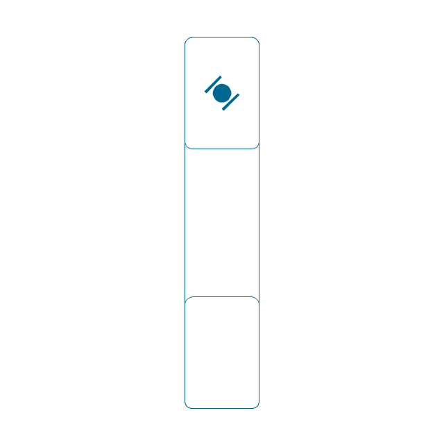
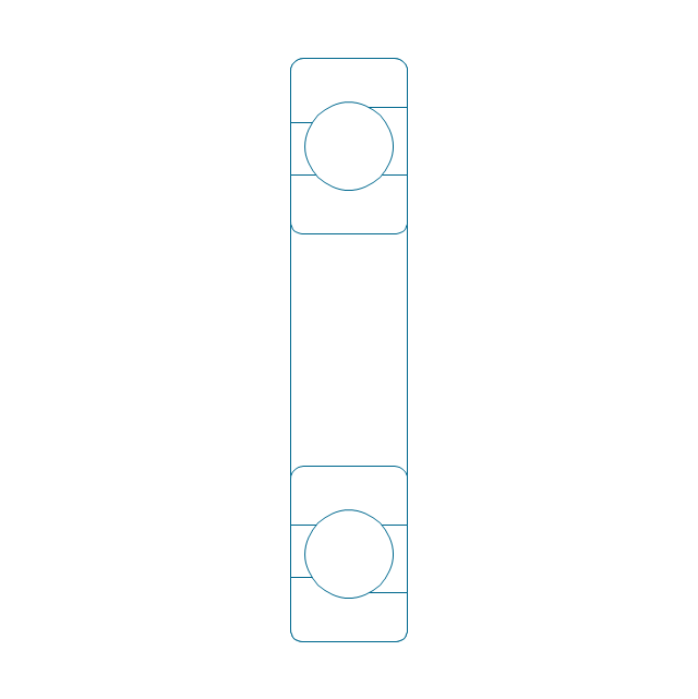
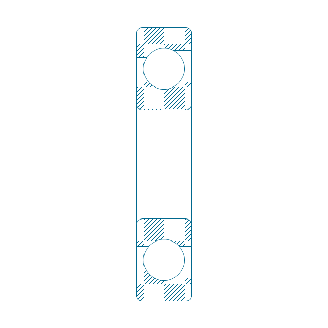
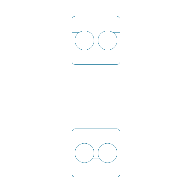
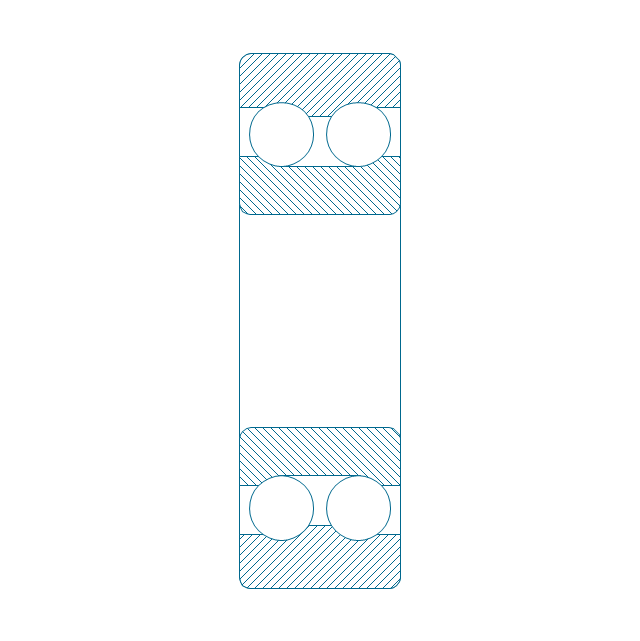
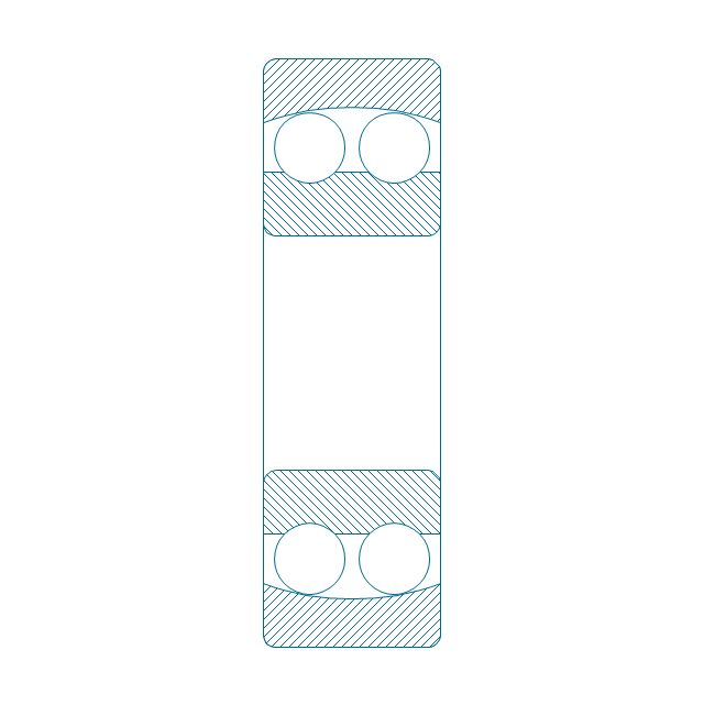
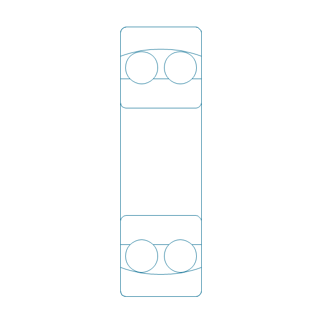
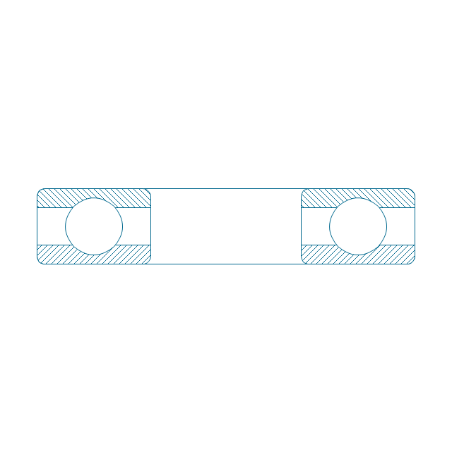
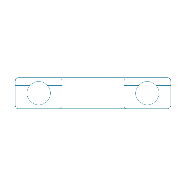
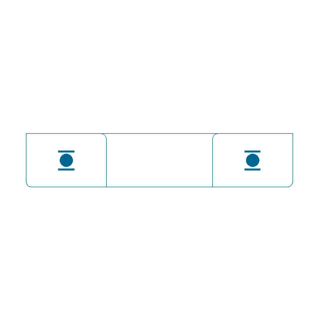
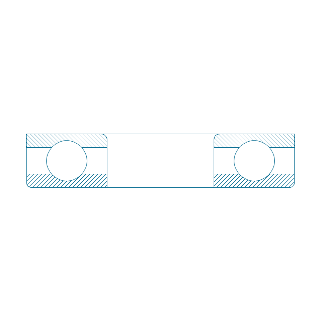
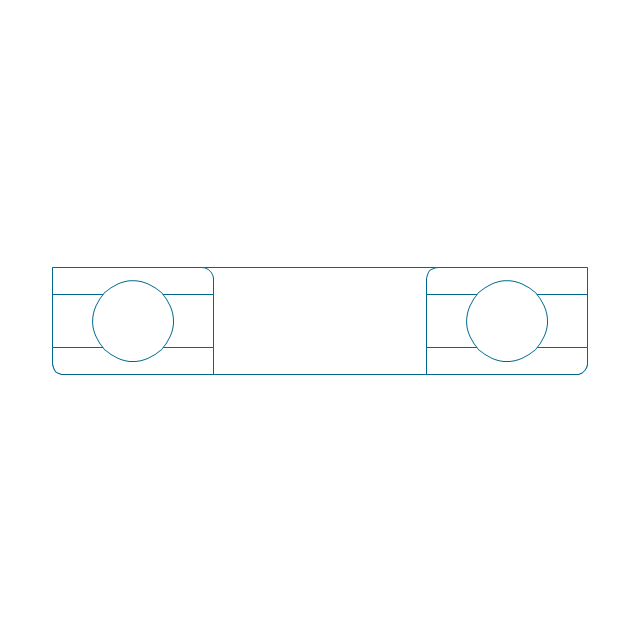
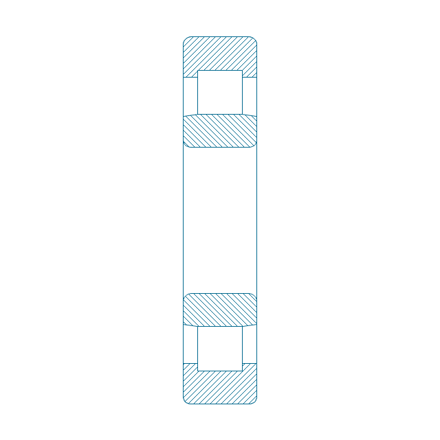
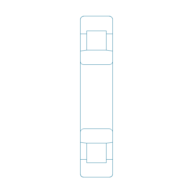
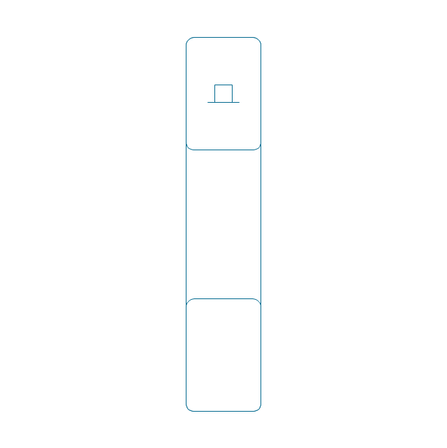
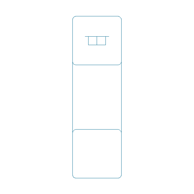
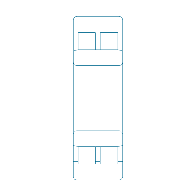
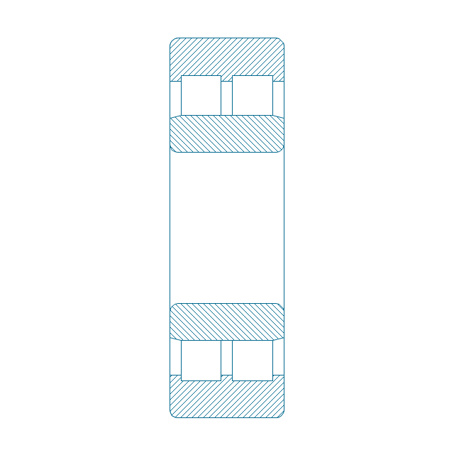
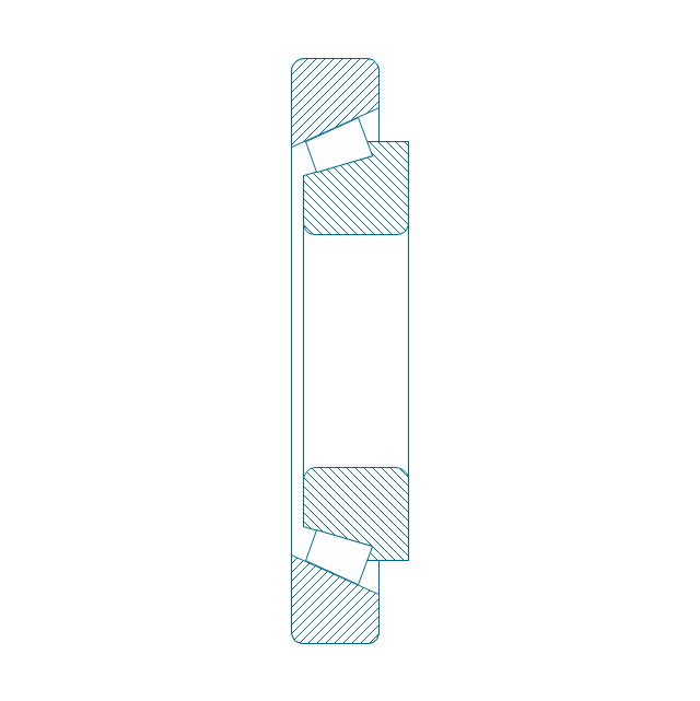
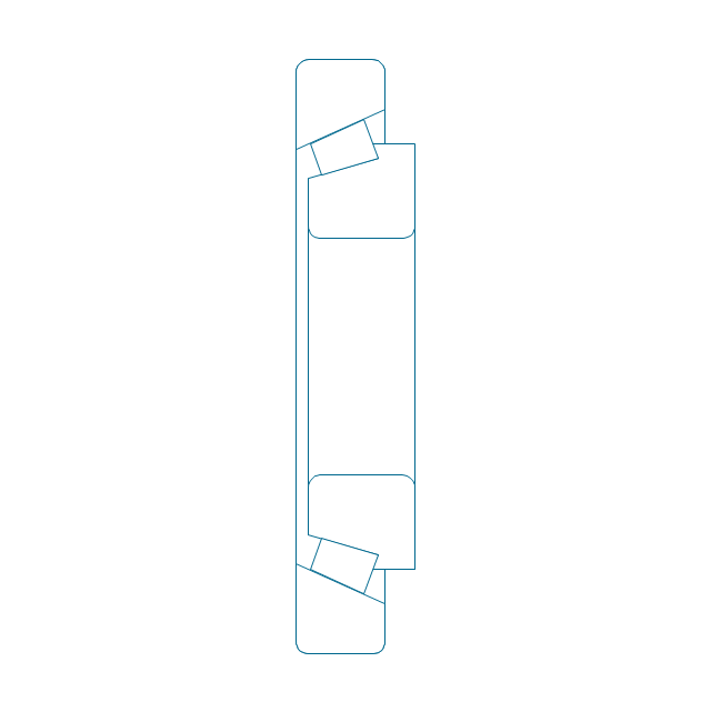
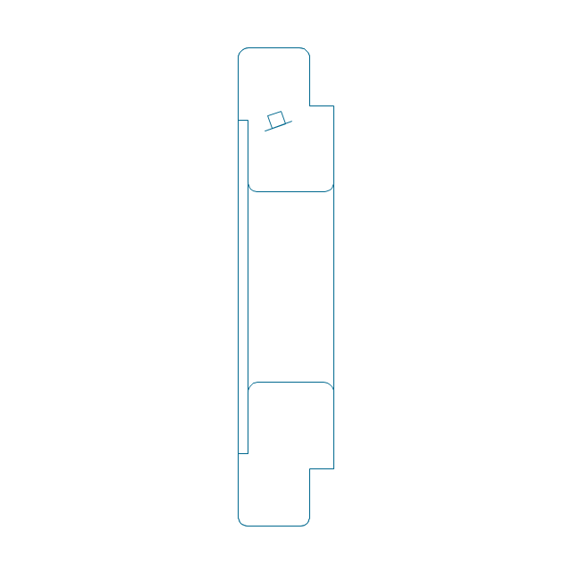
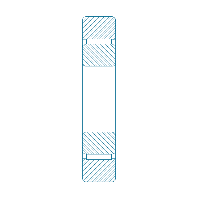
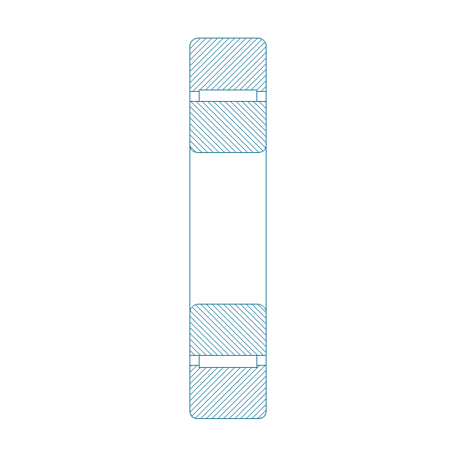
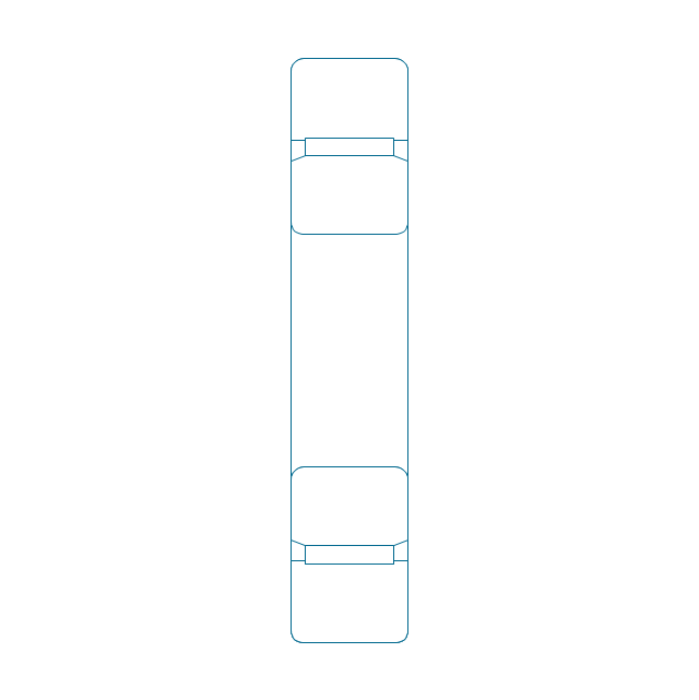
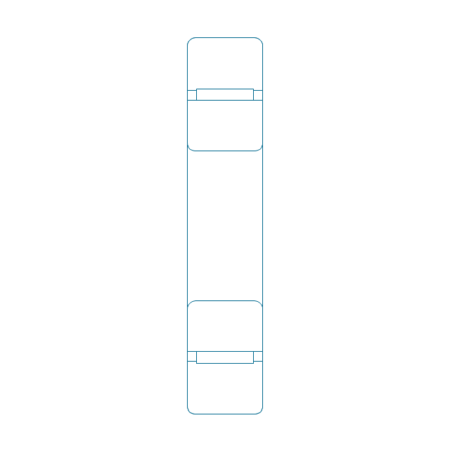
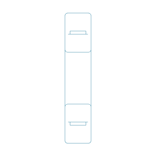
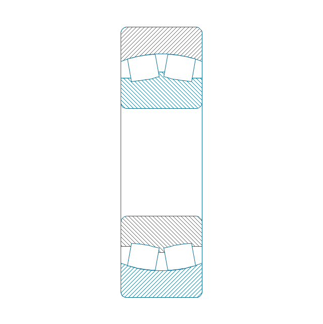
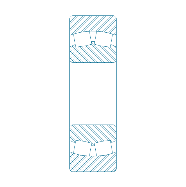
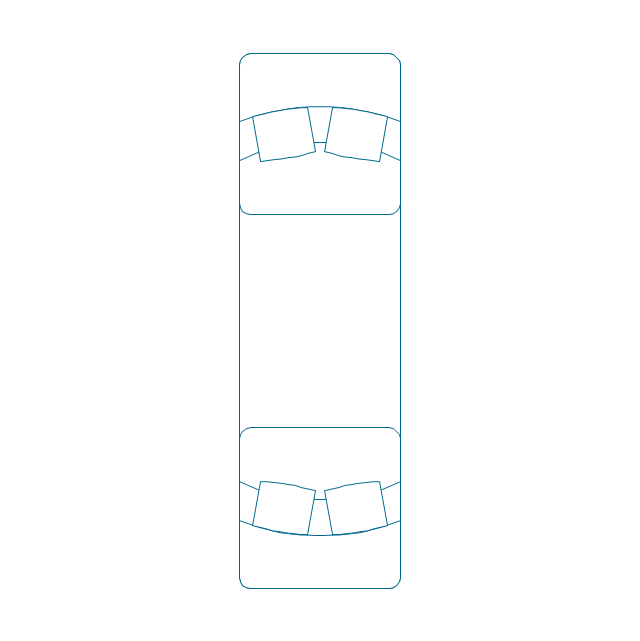
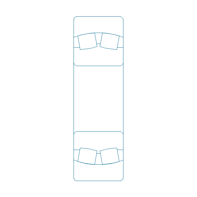
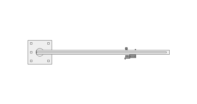
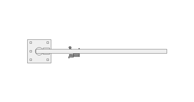
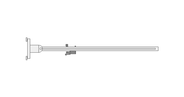
Mechanical Drawings are the special type of technical diagrams that visualize the structure of complex systems and illustrate the information about ventilation, heating, air conditioning, i.e. HVAC systems. These drawings are created on the base of floor plans and reflected ceiling plans, and then become an obligatory part of construction project which is needed directly for construction a building and for receiving a permit on it. Mechanical drawings and diagrams help effectively represent construction, technical and engineering solutions, and also schematics of different mechanical equipment. ConceptDraw DIAGRAM ector drawing software enhanced with Mechanical Engineering solution from Engineering area of ConceptDraw Solution Park provides wide set of effective drawing tools, predesigned mechanical drawing symbols, templates, samples and examples. Use of standardized and recognized mechanical vector symbols helps you design understandable mechanical drawings, diagrams and mechanical engineering schematics.The vector stencils library "Bearings" contains 59 symbols of ball bearings, roller bearings, shafts, springs, gears, hooks, spindles, and keys.
Use it to design engineering drawings of machine tools and mechanical devices in the ConceptDraw PRO diagramming and vector drawing software extended with the Mechanical Engineering solution from the Engineering area of ConceptDraw Solution Park.
www.conceptdraw.com/ solution-park/ engineering-mechanical
Electrical Symbols — Rotating Equipment
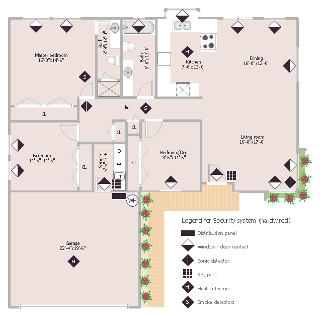
Electrical rotating machines, such as motors and generators, are vital assets for any power plant or large industrial company. An electric motor is an electrical machine that converts electrical energy into mechanical energy. The reverse of this would be the conversion of mechanical energy into electrical energy and is done by an electric generator. In normal motoring mode, most electric motors operate through the interaction between an electric motor's magnetic field and winding currents to generate force within the motor. In certain applications, such as in the transportation industry with traction motors, electric motors can operate in both motoring and generating or braking modes to also produce electrical energy from mechanical energy. 26 libraries of the Electrical Engineering Solution of ConceptDraw DIAGRAM make your electrical diagramming simple, efficient, and effective. You can simply and quickly drop the ready-to-use objects from libraries into your document to create the electrical diagram.This sample was created on the base of the floor plan with security system device symbols from the website of the California State University, Sacramento. [imet.csus.edu/ imet1/ denyer/ mhs_ denyer/ drafting/ arch_ ch_ 31/ 31-28.jpg]
Legend for the security system hardware includes distribution panel, window-door contact, sonic detector, key pads, heat detectors, smoke detectors.
The example "Security system floor plan" was created using the ConceptDraw PRO diagramming and vector drawing software extended with the Security and Access Plans solution from the Building Plans area of ConceptDraw Solution Park.
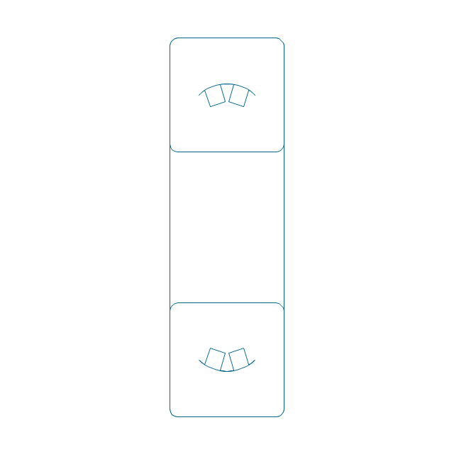
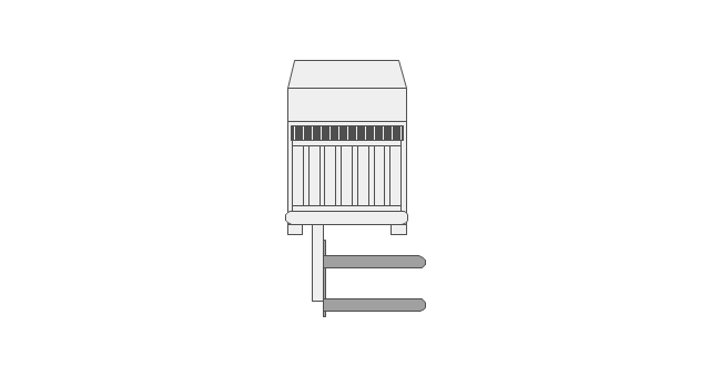
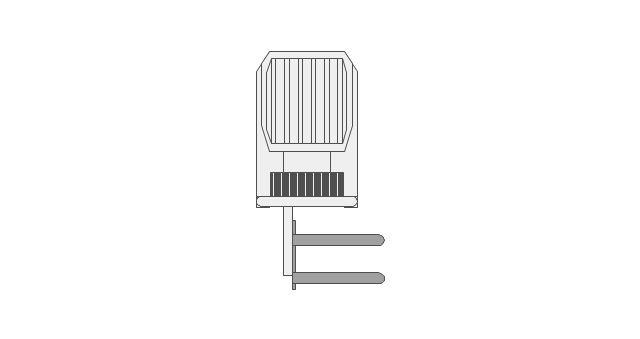
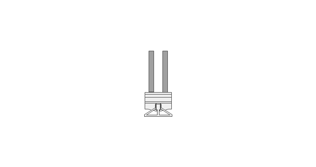
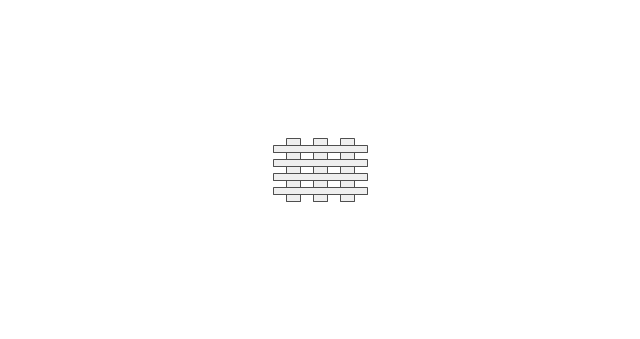
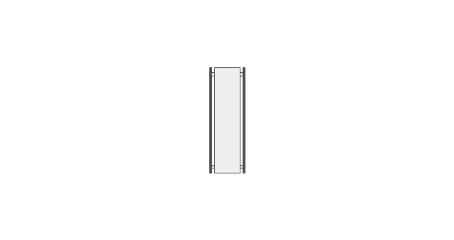
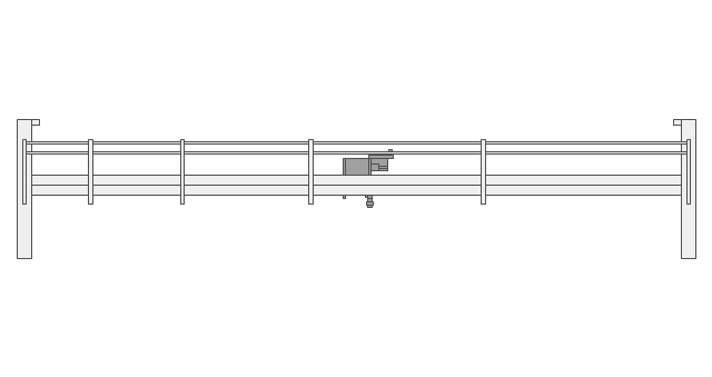
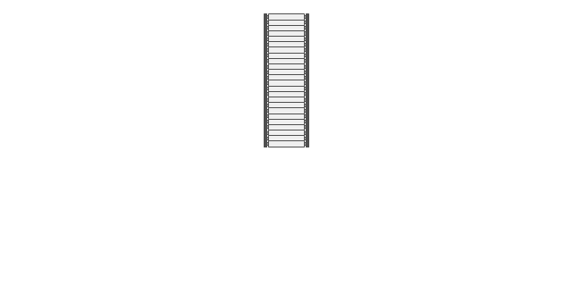
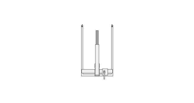
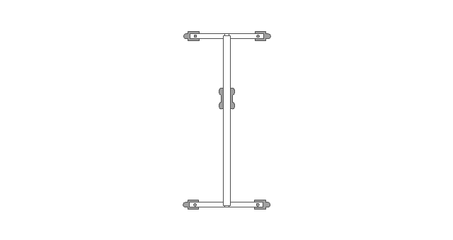
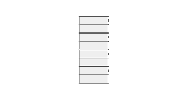
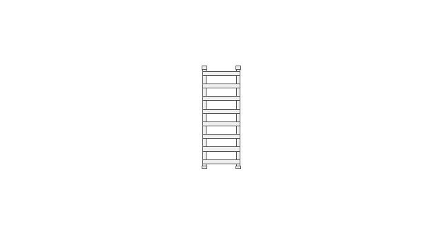
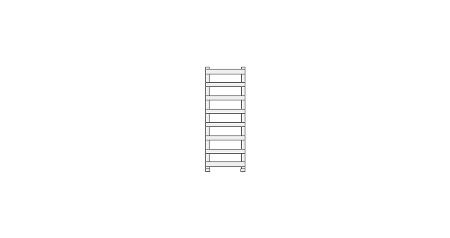
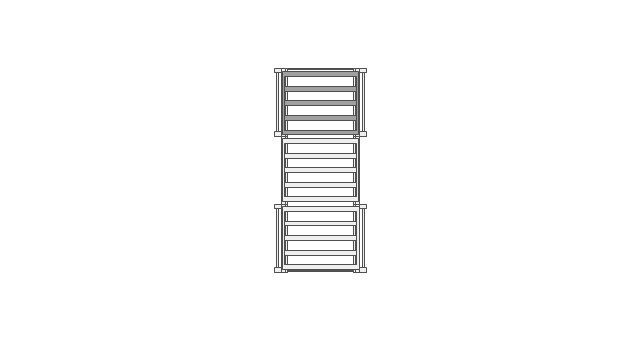
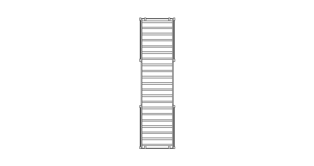
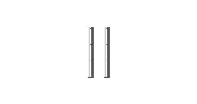
The vector stencils library "Storage and distribution" contains 24 symbols of storage and distribution equipment.
Use it for drawing plant design plans and equipment layouts in the ConceptDraw PRO diagramming and vector drawing software extended with the Plant Layout Plans solution from the Building Plans area of ConceptDraw Solution Park.
www.conceptdraw.com/ solution-park/ building-plant-layout-plans
Use it for drawing plant design plans and equipment layouts in the ConceptDraw PRO diagramming and vector drawing software extended with the Plant Layout Plans solution from the Building Plans area of ConceptDraw Solution Park.
www.conceptdraw.com/ solution-park/ building-plant-layout-plans
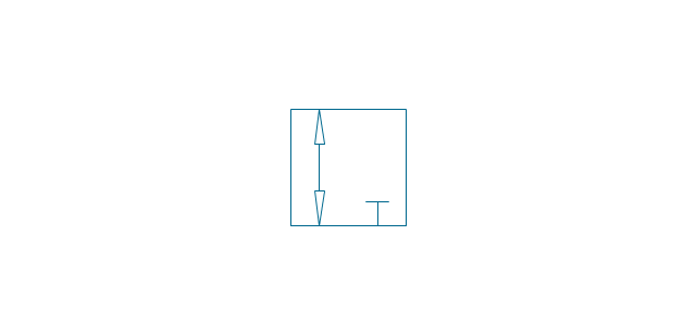
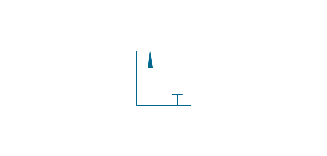
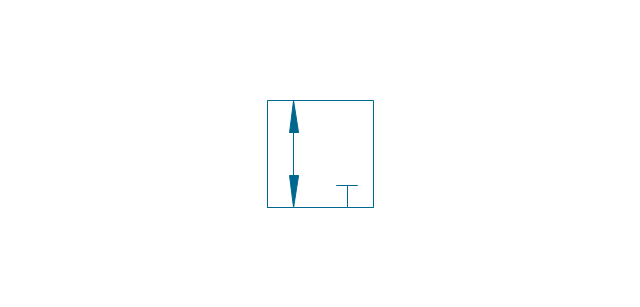
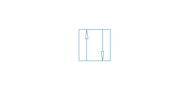
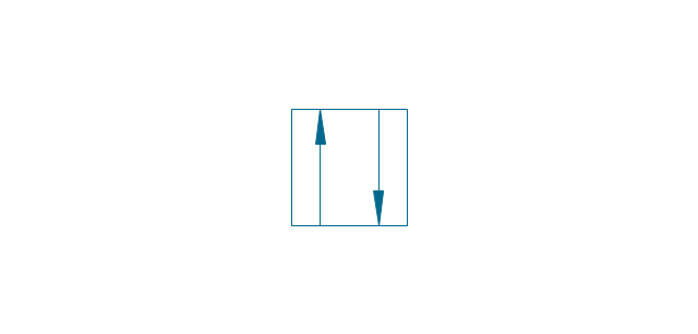
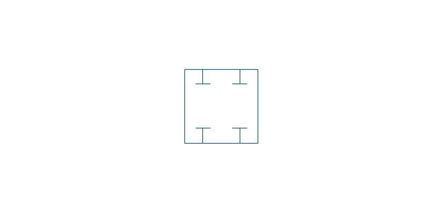
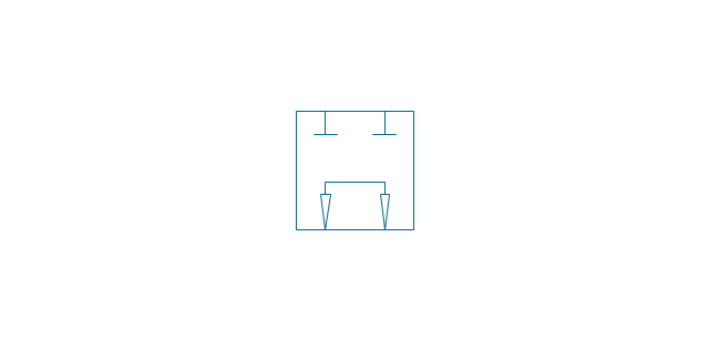
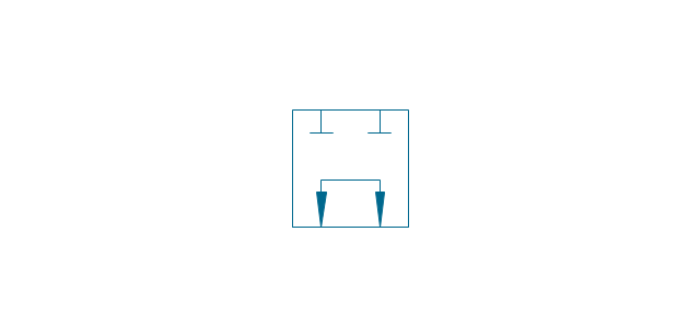
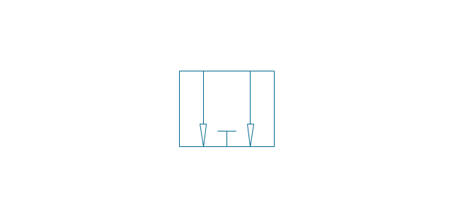
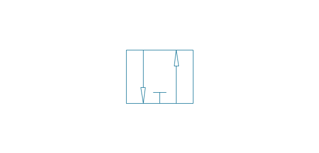
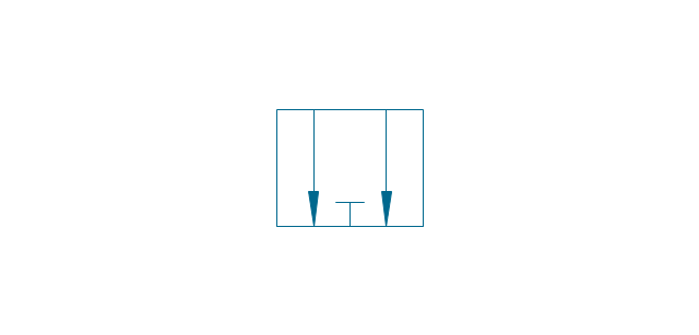
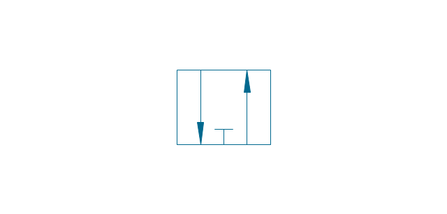
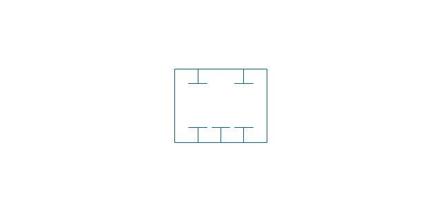
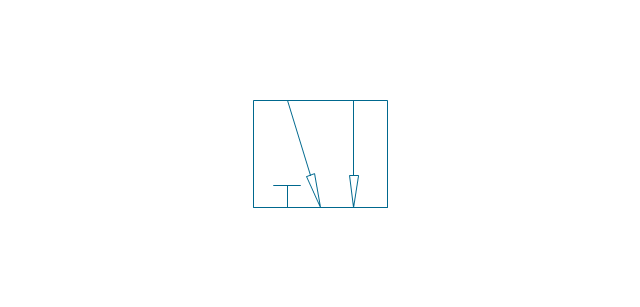
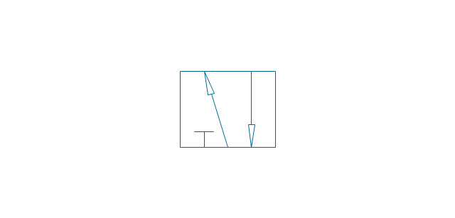
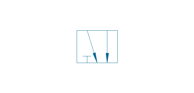
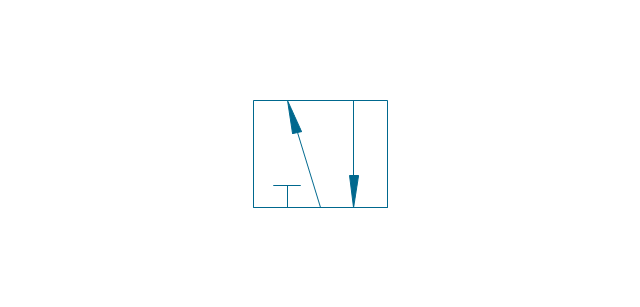
The vector stencils library "Valve assembly" contains 141 symbols of pressure and flow regulators, flow direction indicators, controls, and symbols to design flow paths of control valves in fluid power systems.
Use these valve assembly shapes to design the engineering drawings of hydraulic and pneumatic valve assemblies
in the ConceptDraw PRO diagramming and vector drawing software extended with the Mechanical Engineering solution from the Engineering area of ConceptDraw Solution Park.
www.conceptdraw.com/ solution-park/ engineering-mechanical
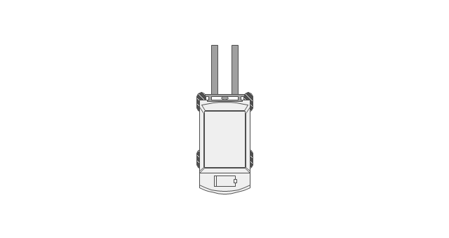
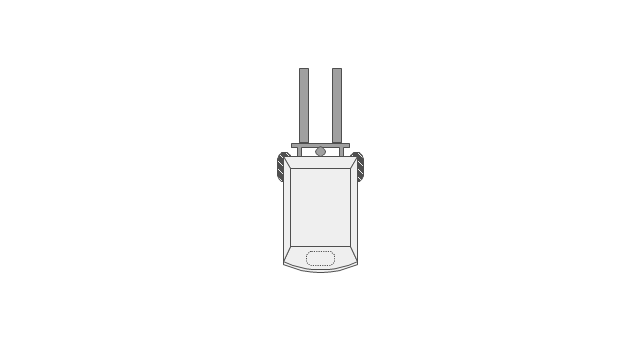
The vector stencils library "Telecommunication networks" contains 32 clipart images of telecommunication network devices and equipment for drawing telecom network diagrams.
"A telecommunications network is a collection of terminal nodes, links and any intermediate nodes which are connected so as to enable telecommunication between the terminals.
The transmission links connect the nodes together. The nodes use circuit switching, message switching or packet switching to pass the signal through the correct links and nodes to reach the correct destination terminal.
Each terminal in the network usually has a unique address so messages or connections can be routed to the correct recipients. The collection of addresses in the network is called the address space." [Telecommunications network. Wikipedia]
The clip art example "Telecommunication networks - Vector stencils library" was created using the ConceptDraw PRO diagramming and vector drawing software extended with the Telecommunication Network Diagrams solution from the Computer and Networks area of ConceptDraw Solution Park.
 Plant Layout Plans
Plant Layout Plans solution can be used for power plant design and plant layout design, for making the needed building plant plans and plant layouts looking professionally good. Having the newest plant layout software, the plant design solutions and in particular the ConceptDraw’s Plant Layout Plans solution, including the pre-made templates, examples of the plant layout plans, and the stencil libraries with the design elements, the architects, electricians, interior designers, builders, telecommunications managers, plant design engineers, and other technicians can use them to create the professionally looking drawings within only a few minutes.
The vector stencils library "Storage and distribution" contains 24 symbols of storage and distribution equipment.
Use it for drawing plant design plans and equipment layouts in the ConceptDraw PRO diagramming and vector drawing software extended with the Plant Layout Plans solution from the Building Plans area of ConceptDraw Solution Park.
www.conceptdraw.com/ solution-park/ building-plant-layout-plans
Use it for drawing plant design plans and equipment layouts in the ConceptDraw PRO diagramming and vector drawing software extended with the Plant Layout Plans solution from the Building Plans area of ConceptDraw Solution Park.
www.conceptdraw.com/ solution-park/ building-plant-layout-plans
- Roll Up Door Symbol Floor Plan
- Garage Door Symbol Floor Plan
- Roll Up Garage Door Floor Plan Symbol
- Roller Conveyor Symbols
- Floor Plans | Roll Up Garage Door Symbol Blueprint
- Design elements - Doors and windows | Doors - Vector stencils ...
- | Sans 0143 Roll Up Garage Door Symbol On Floor Plan
- Floor Plans | Directional Maps | Design elements - Shipping and ...
- Light Switch Symbol Floor Plan
- Switch Symbol Floor Plan
- Garage Door Symbol In House Plan
- Conventional Symbols In Engineering Drawing On Bearings
- Switches - Vector stencils library | Electrical and telecom - Vector ...
- Mechanical Drawing Symbols | Design elements - Bearings ...
- Mechanical Drawing Symbols | Design elements - Bearings ...
- Engineering Drawing Symbol Single Switch Door
- Symbol Of Master Switch
- Floor Plan Symbol Of A Shelf
- Weatherproof Switch Symbol
- Design elements - Switches and relays | What Is The Symbol Of A ...






-bearings---vector-stencils-library.png--diagram-flowchart-example.png)
-bearings---vector-stencils-library.png--diagram-flowchart-example.png)
-bearings---vector-stencils-library.png--diagram-flowchart-example.png)


-bearings---vector-stencils-library.png--diagram-flowchart-example.png)


-bearings---vector-stencils-library.png--diagram-flowchart-example.png)




-valve-assembly---vector-stencils-library.png--diagram-flowchart-example.png)
-valve-assembly---vector-stencils-library.png--diagram-flowchart-example.png)
-valve-assembly---vector-stencils-library.png--diagram-flowchart-example.png)
-valve-assembly---vector-stencils-library.png--diagram-flowchart-example.png)
-valve-assembly---vector-stencils-library.png--diagram-flowchart-example.png)
-valve-assembly---vector-stencils-library.png--diagram-flowchart-example.png)
-valve-assembly---vector-stencils-library.png--diagram-flowchart-example.png)
-valve-assembly---vector-stencils-library.png--diagram-flowchart-example.png)
-valve-assembly---vector-stencils-library.png--diagram-flowchart-example.png)
-valve-assembly---vector-stencils-library.png--diagram-flowchart-example.png)
-valve-assembly---vector-stencils-library.png--diagram-flowchart-example.png)
-valve-assembly---vector-stencils-library.png--diagram-flowchart-example.png)
-valve-assembly---vector-stencils-library.png--diagram-flowchart-example.png)
-valve-assembly---vector-stencils-library.png--diagram-flowchart-example.png)
-valve-assembly---vector-stencils-library.png--diagram-flowchart-example.png)
-valve-assembly---vector-stencils-library.png--diagram-flowchart-example.png)
-valve-assembly---vector-stencils-library.png--diagram-flowchart-example.png)
-valve-assembly---vector-stencils-library.png--diagram-flowchart-example.png)
-valve-assembly---vector-stencils-library.png--diagram-flowchart-example.png)
-valve-assembly---vector-stencils-library.png--diagram-flowchart-example.png)
-valve-assembly---vector-stencils-library.png--diagram-flowchart-example.png)
-valve-assembly---vector-stencils-library.png--diagram-flowchart-example.png)
-valve-assembly---vector-stencils-library.png--diagram-flowchart-example.png)
-valve-assembly---vector-stencils-library.png--diagram-flowchart-example.png)


















-valve-assembly---vector-stencils-library.png--diagram-flowchart-example.png)

-valve-assembly---vector-stencils-library.png--diagram-flowchart-example.png)





-valve-assembly---vector-stencils-library.png--diagram-flowchart-example.png)
-valve-assembly---vector-stencils-library.png--diagram-flowchart-example.png)


-valve-assembly---vector-stencils-library.png--diagram-flowchart-example.png)


