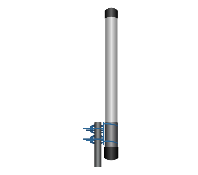
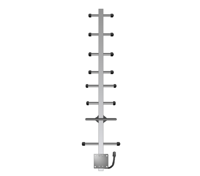
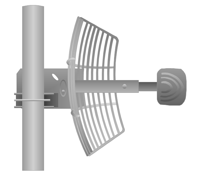
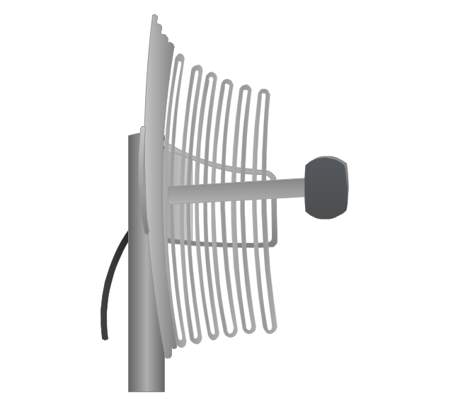
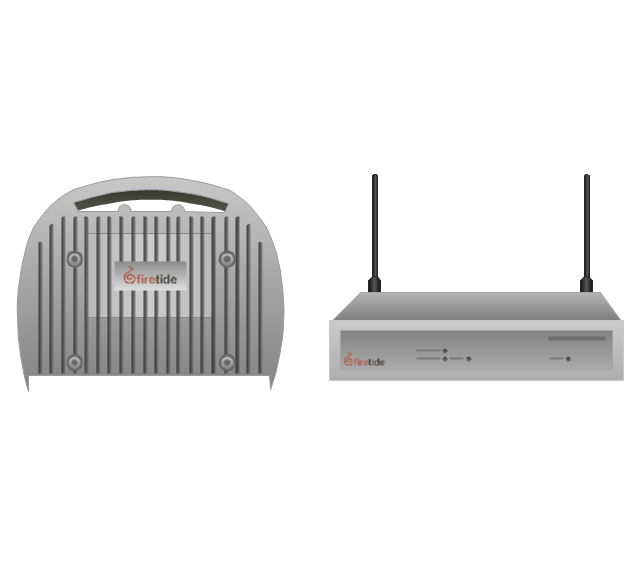
The vector stencils library "Telecom equipment" contains 11 hardware clipart icons of telecommunication devices for drawing computer network diagrams and equipment layouts.
"In telecommunication, a communications system is a collection of individual communications networks, transmission systems, relay stations, tributary stations, and data terminal equipment (DTE) usually capable of interconnection and interoperation to form an integrated whole. The components of a communications system serve a common purpose, are technically compatible, use common procedures, respond to controls, and operate in union. Telecommunications is a method of communication." [Communications system. Wikipedia]
"A basic telecommunication system consists of three primary units that are always present in some form: (1) A transmitter that takes information and converts it to a signal. (2) A transmission medium, also called the "physical channel" that carries the signal. ... (3) A receiver that takes the signal from the channel and converts it back into usable information." [Telecommunication. Wikipedia]
The clip art example "Telecom equipment - Vector stencils library" was created using the ConceptDraw PRO diagramming and vector drawing software extended with the Telecommunication Network Diagrams solution from the Computer and Networks area of ConceptDraw Solution Park.
Wiring Diagrams with ConceptDraw DIAGRAM
A Wiring Diagram is a comprehensive schematic that depicts the electrical circuit system, shows all the connectors, wiring, signal connections (buses), terminal boards between electrical or electronic components and devices of the circuit. Wiring Diagram illustrates how the components are connected electrically and identifies the wires by colour coding or wire numbers. These diagrams are necessary and obligatory for identifying and fixing faults of electrical or electronic circuits, and their elimination. For designing Wiring Diagrams are used the standardized symbols representing electrical components and devices. ConceptDraw Solution Park offers the Electrical Engineering solution from the Engineering area with 26 libraries of graphics design elements and electrical schematic symbols for easy drawing various Wiring Diagrams, Electrical Circuit and Wiring Blueprints, Electrical and Telecom schematics of any complexity, Electrical Engineering Diagrams, Power Systems Diagrams, Repair Diagrams, Maintenance Schemes, etc. in ConceptDraw DIAGRAM software.- Telecommunication Network Diagrams | Telecommunication ...
- Electrical Drawing Software | How To use House Electrical Plan ...
- Telecom equipment - Vector stencils library | Telecom equipment ...
- Stakeholder Onion Diagrams | Telecom equipment - Vector stencils ...
- Providing telecom services - Cross-functional flowchart | Telecom ...
- Example Of Equipment With Telecom Network
- Telecom equipment - Vector stencils library | Telecommunication ...
- Telecom equipment - Vector stencils library | Electrical and Telecom ...
- Telecom equipment - Vector stencils library | Design Elements ...
- Telecom equipment - Vector stencils library | Cross-Functional ...
- Digital Communications Network. Computer and Network Examples ...
- Telecom equipment - Vector stencils library | Telecommunication ...
- Telecommunication Network Diagrams | Telecommunication ...
- Telecom equipment - Vector stencils library | Entity-Relationship ...
- Telecom equipment - Vector stencils library | Network Diagramming ...
- Telecom equipment - Vector stencils library | Design Elements ...
- Copying Service Process Flowchart. Flowchart Examples | Process ...
- Telecom equipment - Vector stencils library | Telecommunication ...
- How To use Electrical and Telecom Plan Software | Electric and ...
- Communications - Vector stencils library | Telecom equipment ...





-telecom-equipment---vector-stencils-library.png--diagram-flowchart-example.png)
