HelpDesk
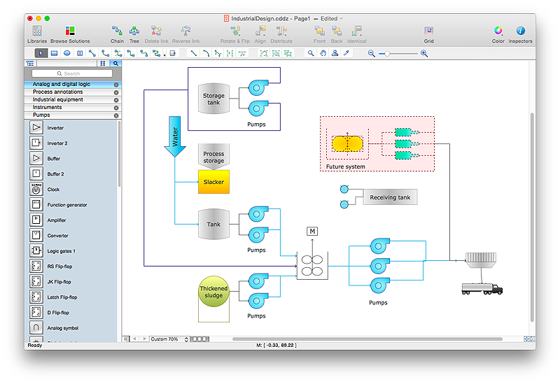
How to Draw a Process Flow Diagram in ConceptDraw PRO
Process Flow diagrams are used in chemical and process engineering to show the flow of chemicals and the equipment involved in the process. When it comes to creating a process flow diagram, it's important to use software that is capable of describing a wide range of processes, using techniques and graphical notation that are easily recognized by engineering workers. An ideal drawing platform will utilize functions that can cope with the output of a high volume of engineering processes, that may change rapidly from development to implementation stages. ConceptDraw PRO, with the extended functionality of the Chemical and Process Engineering Diagrams solution, is the ideal medium for creating designs of this type. The Chemical and Process Engineering Diagrams solution complements this feature with a library of selected icons to represent various steps — all instantly recognizable and applicable to a wide user base. ConceptDraw PRO allows you to draw the Process Flow diagram easily using the set of special libraries.
 Plant Layout Plans
This solution extends ConceptDraw PRO v.9.5 plant layout software (or later) with process plant layout and piping design samples, templates and libraries of vector stencils for drawing Plant Layout plans. Use it to develop plant layouts, power plant desig
 Fishbone Diagram
Fishbone Diagrams solution extends ConceptDraw PRO software with templates, samples and library of vector stencils for drawing the Ishikawa diagrams for cause and effect analysis.
HelpDesk
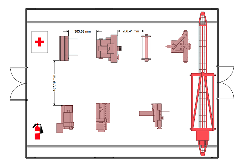
How to Create a Plant Layout Design
A plant construction process begins from a plant layout stage - an engineering stage used to design, analyze and finally choose the suitable configurations for a manufacturing plant. Plant Layout issues are core to any enterprise and are challenged in all types of manufacturing process. The sufficiency of layout influences the efficiency of subsequent operations. It is an important background for efficient manufacturing and also has a great deal with many questions. Once the place of the plant has been determined, the next important task before the management of the plant is to plan appropriate layout for the enterprise. Plant layout is used to create the most effective physical arrangement of machinery and equipment, with the plant building in such a manner so as to make quickest and cheapest way from a raw material to the shipment of the completed product Making a plan that shows the location of industrial equipment involves many different elements that can be managed using Con
 Manufacturing and Maintenance
Manufacturing and maintenance solution extends ConceptDraw PRO software with illustration samples, templates and vector stencils libraries with clip art of packaging systems, industrial vehicles, tools, resources and energy.
- Electrical Drawing Software | How To use House Electrical Plan ...
- Process Flowchart | Piping and Instrumentation Diagram Software ...
- What Are Tje Three Main Areas In Bubble Diagrams
- How To use House Electrical Plan Software | CAD Drawing Software ...
- Electrical Floor Plan
- How To use House Electrical Plan Software | CAD Drawing Software ...
- Factory layout floor plan | Piping and Instrumentation Diagram ...
- Electrical Drawing Software | CAD Drawing Software for Making ...
- Process Flowchart | Process Flow Diagram Symbols | Process ...
- How To use House Electrical Plan Software | Electric and Telecom ...
- Engineering | Electrical Drawing Software | How To use Electrical ...
- Flowcharts | What is a Diagram Area | Marketing Diagrams ...
- How To use House Electrical Plan Software | Electrical Diagram ...
- Manufacturing 8 Ms fishbone diagram - Template | Data Flow ...
- The Organizational Planning Process With Diagram
- Which Diagram Shows Only What The System Does
- Electrical Drawing Software | How To use House Electrical Plan ...
- Piping and instrumentation diagram template | Piping and ...
- How to Create a HR Process Flowchart Using ConceptDraw PRO ...
- Electrical Engineering | How to Create an Electrical Diagram Using ...

