Bubble diagrams in Landscape Design with ConceptDraw DIAGRAM
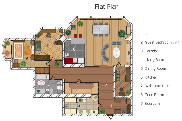
Bubble Diagrams are the charts with a bubble presentation of data with obligatory consideration of bubble's sizes. They are analogs of Mind Maps and find their application at many fields, and even in landscape design. At this case the bubbles are applied to illustrate the arrangement of different areas of future landscape design, such as lawns, flowerbeds, playgrounds, pools, recreation areas, etc. Bubble Diagram helps to see instantly the whole project, it is easy for design and quite informative, in most cases it reflects all needed information. Often Bubble Diagram is used as a draft for the future landscape project, on the first stage of its design, and in case of approval of chosen design concept is created advanced detailed landscape plan with specification of plants and used materials. Creation of Bubble Diagrams for landscape in ConceptDraw DIAGRAM software is an easy task thanks to the Bubble Diagrams solution from "Diagrams" area. You can use the ready scanned location plan as the base or create it easy using the special ConceptDraw libraries and templates.This flat design floor plan sample shows layout of furniture, kitchen equipment and bathroom appliance.
"An apartment (in American English) or flat in British English is a self-contained housing unit (a type of residential real estate) that occupies only part of a building. Such a building may be called an apartment building, apartment house (in American English), block of flats, tower block, high-rise or, occasionally mansion block (in British English), especially if it consists of many apartments for rent. In Scotland it is often called a tenement, which has a pejorative connotation elsewhere. Apartments may be owned by an owner/ occupier by leasehold tenure or rented by tenants (two types of housing tenure).
Apartments can be classified into several types. In North America the typical terms are a studio, efficiency or bachelor apartment (bedsit in the UK). These all tend to be the smallest apartments with the cheapest rents in a given area. This kind of apartment usually consists mainly of a large room which is the living, dining and bedroom combined. There are usually kitchen facilities as part of this central room, but the bathroom is a separate, smaller room.
Moving up from the bachelors/ efficiencies are one-bedroom apartments, in which one bedroom is separate from the rest of the apartment. Then there are two-bedroom, three-bedroom, etc. apartments. Small apartments often have only one entrance.
Large apartments often have two entrances, perhaps a door in the front and another in the back. Depending on the building design, the entrance doors may be directly to the outside or to a common area inside, such as a hallway. Depending on location, apartments may be available for rent furnished with furniture or unfurnished into which a tenant moves in with their own furniture." [Apartment. Wikipedia]
The example "Flat design floor plan" was created using the ConceptDraw PRO diagramming and vector drawing software extended with the Floor Plans solution from the Building Plans area of ConceptDraw Solution Park.
This cafe electrical floor plan sample shows the outlet and switch layout.
"An electrical drawing, is a type of technical drawing that shows information about power, lighting, and communication for an engineering or architectural project. Any electrical working drawing consists of "lines, symbols, dimensions, and notations to accurately convey an engineering's design to the workers, who install the electrical system on the job".
A complete set of working drawings for the average electrical system in large projects usually consists of:
(1) A plot plan showing the building's location and outside electrical wiring.
(2) Floor plans showing the location of electrical systems on every floor.
(3) Power-riser diagrams showing panel boards.
(4) Control wiring diagrams.
(5) Schedules and other information in combination with construction drawings.
Electrical drafters prepare wiring and layout diagrams used by workers who erect, install, and repair electrical equipment and wiring in communication centers, power plants, electrical distribution systems, and buildings." [Electrical drawing. Wikipedia]
The outlet and switch layout example "Cafe electrical floor plan" was created using the ConceptDraw PRO diagramming and vector drawing software extended with the Electric and Telecom Plans solution from the Building Plans area of ConceptDraw Solution Park.
 Network Layout Floor Plans
Network Layout Floor Plans solution extends ConceptDraw DIAGRAM software functionality with powerful tools for quick and efficient documentation the network equipment and displaying its location on the professionally designed Network Layout Floor Plans. Never before creation of Network Layout Floor Plans, Network Communication Plans, Network Topologies Plans and Network Topology Maps was not so easy, convenient and fast as with predesigned templates, samples, examples and comprehensive set of vector design elements included to the Network Layout Floor Plans solution. All listed types of plans will be a good support for the future correct cabling and installation of network equipment.
"A fast casual restaurant is a type of restaurant that does not offer full table service, but promises a higher quality of food and atmosphere than a fast food restaurant. In the US, it is a relatively new and growing concept positioned between fast food and casual dining." [Fast casual restaurant. Wikipedia]
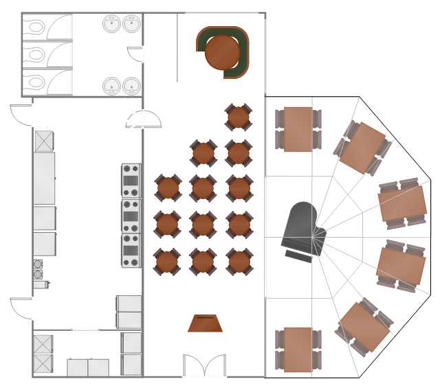
The example "Restaurant floor plan" was created using the ConceptDraw PRO diagramming and vector drawing software extended with the Cafe and Restaurant solution from the Building Plans area of ConceptDraw Solution Park.
The example "Restaurant floor plan" was created using the ConceptDraw PRO diagramming and vector drawing software extended with the Cafe and Restaurant solution from the Building Plans area of ConceptDraw Solution Park.
- Kinds Of Wall Symbol In Floor Plan
- Creative classroom floor plan | Classroom furniture and equipment ...
- Flat design floor plan | Bachelor Type Flat Floor Plan
- Flat design floor plan | Classroom floor plan | Rolling Door And ...
- Doors Vector Plan
- Network Layout Floor Plans | Ethernet local area network layout floor ...
- Cafe electrical floor plan | Design elements - Outlets | Show A ...
- Network Layout Floor Plans | Design elements - Network layout ...
- How To Create Restaurant Floor Plan in Minutes | Cafe and ...
- What Type Of Floorplan Is Suitable To Prevent
- How To Create Restaurant Floor Plan in Minutes | Design elements ...
- Network Layout Floor Plans | Design elements - Network layout ...
- Restaurant Floor Plans Samples | How To Create Restaurant Floor ...
- Flat design floor plan | Plumbing and Piping Plans | How to Draw a ...
- Flat design floor plan | House floor plan | Floor Plans | Bathroom ...
- Design elements - Walls, shell and structure | Floor Plans | Design ...
- Cafe and Restaurant Floor Plans | How To Create Restaurant Floor ...
- Flat design floor plan | How To use Kitchen Design Software ...
- Warehouse layout floor plan | Warehouse with conveyor system ...
- Fast casual restaurant floor plan | Design elements - Cafe and ...


