Basic Flowchart Symbols and Meaning
Flowcharts are the best for visually representation the business processes and the flow of a custom-order process through various departments within an organization. ConceptDraw PRO diagramming and vector drawing software extended with Flowcharts solution offers the full set of predesigned basic flowchart symbols which are gathered at two libraries: Flowchart and Flowcharts Rapid Draw. Among them are: process, terminator, decision, data, document, display, manual loop, and many other specific symbols. The meaning for each symbol offered by ConceptDraw gives the presentation about their proposed use in professional Flowcharts for business and technical processes, software algorithms, well-developed structures of web sites, Workflow diagrams, Process flow diagram and correlation in developing on-line instructional projects or business process system. Use of ready flow chart symbols in diagrams is incredibly useful - you need simply drag desired from the libraries to your document and arrange them in required order. There are a few serious alternatives to Visio for Mac, one of them is ConceptDraw PRO. It is one of the main contender with the most similar features and capabilities.
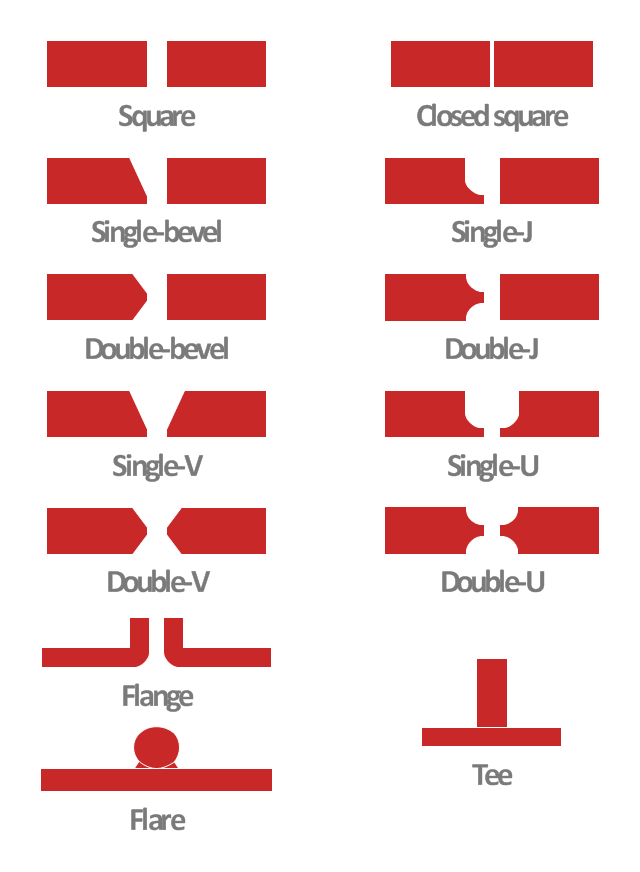
This engineering drawing shows different types of geometry of butt welds.
"Welds can be geometrically prepared in many different ways. The five basic types of weld joints are the butt joint, lap joint, corner joint, edge joint, and T-joint (a variant of this last is the cruciform joint). Other variations exist as well - for example, double-V preparation joints are characterized by the two pieces of material each tapering to a single center point at one-half their height. Single-U and double-U preparation joints are also fairly common - instead of having straight edges like the single-V and double-V preparation joints, they are curved, forming the shape of a U. Lap joints are also commonly more than two pieces thick - depending on the process used and the thickness of the material, many pieces can be welded together in a lap joint geometry." [Welding. Wikipedia]
This engineering drawing example was redesigned using the ConceptDraw PRO diagramming and vector drawing software from the Wikimedia Commons file: Butt Weld Geometry.GIF.
[commons.wikimedia.org/ wiki/ File:Butt_ Weld_ Geometry.GIF]
The engineering drawing example "Butt weld geometry" is included in the Mechanical Engineering solution from the Engineering area of ConceptDraw Solution Park.
- Common joint types | Welded joints types | Butt weld geometry ...
- Welding symbols | Welded joints types | Butt weld geometry | Edge ...
- Examples Of Corner Joint
- Butt weld geometry | Welded joints types | Common joint types ...
- Edge Joint Drawing
- Double V Butt Joint Drawing
- How to Draw Geometric Shapes in ConceptDraw PRO ...
- Types Of Diagrams In Geometry
- Examples Of A Corner Joint
- Examples Of Corner Welding Joint
- Butt Joint Diagram Com
- Welded Joint Diagram
- Butt Joint Diagrams
- Double U Butt Joints Drawing
- Technical drawing - Machine parts assembling | Engineering ...
- Welded joints types | Butt weld geometry | Common joint types ...
- Welded joints types | Common joint types | Mechanical Engineering ...
- Welded joints types | Butt weld geometry | Design elements ...
- Butt weld geometry | Design elements - Welding | Draw The Different ...
- Butt weld geometry | Welding symbols | Elements location of a ...

