Electrical Schematics

This vector stencils library contains 12 object schematic symbols.
Use it to design your IDEF3 diagrams with ConceptDraw PRO diagramming and vector drawing tools.
The vector stencils library "IDEF3 object schematic symbols" is included in the IDEF Business Process Diagrams solution from the Business Processes area of ConceptDraw Solution Park.
Use it to design your IDEF3 diagrams with ConceptDraw PRO diagramming and vector drawing tools.
The vector stencils library "IDEF3 object schematic symbols" is included in the IDEF Business Process Diagrams solution from the Business Processes area of ConceptDraw Solution Park.
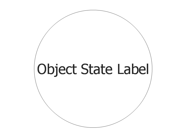
Object
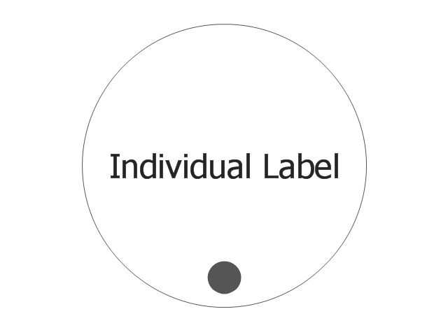
Individual
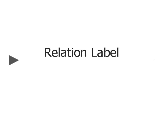
Weak Transition Link

Strong Transition Link

n-Place 1st-order Relation
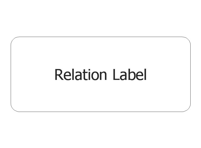
2-Place 2nd-order Relation
AND Junction (object)
-vector-stencils-library---idef3-object-schematic-symbols.png--diagram-flowchart-example.png)
OR Junction (object)
-vector-stencils-library---idef3-object-schematic-symbols.png--diagram-flowchart-example.png)
XOR Junction (object)
-vector-stencils-library---idef3-object-schematic-symbols.png--diagram-flowchart-example.png)
Connecting arrow
Connecting line

Temporal Indeterminacy Marker

This vector stencils library contains 12 process schematic symbols.
Use it to design your IDEF3 diagrams with ConceptDraw PRO diagramming and vector drawing tools.
The vector stencils library "IDEF3 process schematic symbols" is included in the IDEF Business Process Diagrams solution from the Business Processes area of ConceptDraw Solution Park.
Use it to design your IDEF3 diagrams with ConceptDraw PRO diagramming and vector drawing tools.
The vector stencils library "IDEF3 process schematic symbols" is included in the IDEF Business Process Diagrams solution from the Business Processes area of ConceptDraw Solution Park.
Unit of Behavior (UOB)
-vector-stencils-library---idef3-process-schematic-symbols.png--diagram-flowchart-example.png)
Simple Precedence Link

General Constraint Precedence Link

Direction Constraint Precedence Link

Opposite Direction Constraint Precedence Link
Both Directions Constraint Precedence Link

Relational Link

AND Junction (process)
-vector-stencils-library---idef3-process-schematic-symbols.png--diagram-flowchart-example.png)
OR Junction (process)
-vector-stencils-library---idef3-process-schematic-symbols.png--diagram-flowchart-example.png)
Synchronous AND Junction
Synchronous OR Junction

XOR Junction

Making Mechanical Diagram

Electrical Symbols, Electrical Schematic Symbols

The vector stencils library "IDEF3 process schematic symbols" contains 12 shapes: unit of behavior (UOB), links, junctions, .
Use it to design your IDEF3 process schematic diagrams.
"Process schematics tend to be the most familiar and broadly used component of the IDEF3 method. These schematics provide a visualization mechanism for processcentered descriptions of a scenario. The graphical elements that comprise process schematics include Unit of Behavior (UOB) boxes, precedence links, junctions, referents, and notes. The building blocks here are:
- Unit of Behavior (UOB) boxes.
- Links: Links are the glue that connect UOB boxes to form representations of dynamic processes.
- Simple Precedence Links: Precedence links express temporal precedence relations between instances of one UOB and those of another.
- Activation Plots: Activation plots are used to represent activations.
- Dashed Links: Dashed links carry no predefined semantics.
- Link Numbers: All links have an elaboration and unique link numbers.
Activation Semantics for Nonbranching Process Schematics.
- Junctions: Junctions in IDEF3 provide a mechanism to specify the logic of process branching.
- UOB Decompositions: Elaborations capture and structure detailed knowledge about processes.
- UOB Reference Numbering Scheme: A UOB box number is assigned to each UOB box in an IDEF3 Process Description.
- Partial Descriptions: UOB boxes are joined together by links. Because of the description capture focus of IDEF3, it is possible to conceive of UOBs without links to other parts of an IDEF3 schematic.
- Referents: Referents enhance understanding, provide additional meaning, and simplify the construction (i.e., minimize clutter) of both process schematics and object schematics." [IDEF3. Wikipedia]
The shapes example "Design elements - IDEF3 process schematic symbols" was created using the ConceptDraw PRO diagramming and vector drawing software extended with the solution "IDEF Business Process Diagrams" from the area "Business Processes" of ConceptDraw Solution Park.
IDEF3 business process diagram

Electrical Schematic

Block Diagram Creator

How To use House Electrical Plan Software


Building Drawing Software for Designing Plumbing


Mechanical Engineering

The vector stencils library "IDEF3 object schematic symbols" contains 12 shapes: objects, links, relations, junctions, connection arrow and line, temporal indeterminacy marker. Use it to design your IDEF3 object schematic diagrams.
"Object Schematics.
IDEF offers a series of building blocks to express detailed object-centered process information; that is, information about how objects of various kinds are transformed into other kinds of things through a process, or how objects of a given kind change states through a process.
- Objects : An object of a certain kind, like a chassis, will be represented simply by a circle containing an appropriate label.
- Object States : A certain kind of object being in a certain state will be represented by a circle with a label that captures the kind itself and a corresponding state, representing thereby the type, or class, of objects that are in that state.
- Object schematics : The construction of complex representations built from kind symbols and object state symbols.
- Transition Schematics : The first and most basic construct is the basic state transition schematic or simply, transition schematic." [IDEF3. Wikipedia]
The shapes example "Design elements - IDEF3 object schematic symbols" was created using the ConceptDraw PRO diagramming and vector drawing software extended with the solution "IDEF Business Process Diagrams" from the area "Business Processes" of ConceptDraw Solution Park.
IDEF3 object schematic symbols

Geo Map - Asia - Turkmenistan

Cisco Network Topology

Mechanical Drawing Software

Local area network (LAN). Computer and Network Examples
 diagram")

Electrical Symbols — Transformers and Windings

Piping and Instrumentation Diagram Software

Network Diagram Software Home Area Network

HelpDesk
How to Create a CCTV Diagram

- Design elements - IDEF3 process schematic symbols | Vector ...
- Laboratory equipment - Vector stencils library | Network Diagram ...
- Vector stencils library - IDEF3 object schematic symbols | Design ...
- Vector stencils library - IDEF3 process schematic symbols | Vector ...
- Final object schematic - IDEF3 diagram | Vector stencils library ...
- Mechanics - Vector stencils library | Physics | Physics Symbols ...
- GPRS network diagram | Telecommunication networks - Vector ...
- Design elements - IDEF3 process schematic symbols | IDEF ...
- Vector stencils library - IDEF3 process schematic symbols
- Amine treating unit schematic diagram | Heating equipment - Vector ...
- Lighting - Vector stencils library | Design elements - Lighting ...
- How to create an IDEF3 diagram using ConceptDraw PRO | Vector ...
- Electrical and telecom - Vector stencils library | Plug Or Outlet ...
- Vector stencils library - IDEF3 object schematic symbols
- Process Flow Diagram Symbols | Design elements - Heating ...
- Electrical Symbols, Electrical Diagram Symbols | Electrical Symbols ...
- Retract resistor check valve application | Valves - Vector stencils ...
- Catabolism schematic - Biochemical diagram | Glycolysis overview ...
- Hydraulic 4-ported 3-position valve template - Win | Valves - Vector ...