How To use Appliances Symbols for Building Plan

How To use House Electrical Plan Software


Symbol for Pool Table for Floor Plans

The vector stencils library "Network layout floorplan" contain 34 symbol icons for drawing computer network floor plans and communication equipment and cabling layouts.
"Networking hardware may also be known as network equipment or computer networking devices. Units which are the last receiver or generate data are called hosts or data terminal equipment.
All these terms refer to devices facilitating the use of a computer network. Specifically, they mediate data in a computer network. ...
Typically, networking hardware includes gateways, routers, network bridges, switches, hubs, and repeaters. But it also includes hybrid network devices such as multilayer switches, protocol converters, bridge routers, proxy servers, firewalls, network address translators, multiplexers, network interface controllers, wireless network interface controllers, modems, ISDN terminal adapters, line drivers, wireless access points, networking cables and other related hardware.
The most common kind of networking hardware today is a copper-based Ethernet adapter because of its standard inclusion on most modern computer systems. Wireless networking has, however, become increasingly popular, especially for portable and handheld devices.
Other hardware prevalent in computer networking includes data center equipment (such as file servers, database servers and storage areas), network services (such as DNS, DHCP, email, etc.) as well as devices which assure content delivery." [Networking hardware. Wikipedia]
The shapes example "Design elements - Network layout floorplan" was created using the ConceptDraw PRO diagramming and vector drawing software extended with the Network Layout Floor Plans solution from the Computer and Networks area of ConceptDraw Solution Park.
Network layout floor plan symbols

The design elements library Walls, shell and structure contains 29 symbols of structural elements: walls, rooms, windows, doors, pillars.
Use the vector stencils library Walls, shell and structure to draw the floor plans and other architectural drawings, blueprints, home and building interior design, space layout plans, construction and house framing diagrams using the ConceptDraw PRO diagramming and vector drawing software.
"A wall is a horizontal structure, usually solid, that defines and sometimes protects an area. Most commonly, a wall delineates a building and supports its superstructure, separates space in buildings into sections, or protects or delineates a space in the open air. There are three principal types of structural walls: building walls, exterior boundary walls, and retaining walls.
Building walls have one main purpose: to support roofs and ceilings. Such walls most often have three or more separate components. In today's construction, a building wall will usually have the structural elements (such as 2×4 studs in a house wall), insulation, and finish elements or surface (such as drywall or panelling). In addition, the wall may house various types of electrical wiring or plumbing. Electrical outlets are usually mounted in walls.
Building walls frequently become works of art externally and internally, such as when featuring mosaic work or when murals are painted on them; or as design foci when they exhibit textures or painted finishes for effect.
In architecture and civil engineering, the term curtain wall refers to the facade of a building which is not load-bearing but functions as decoration, finish, front, face, or history preservation." [Wall. Wikipedia]
This shapes library Walls, shell and structure is provided by the Floor Plans solution from the Building Plans area of ConceptDraw Solution Park.

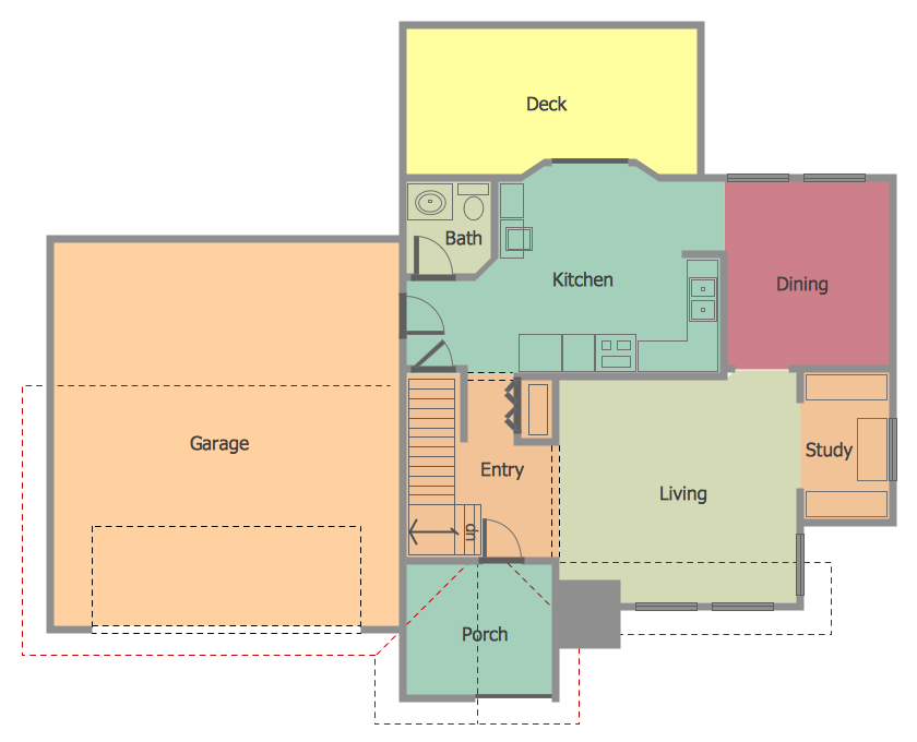
How To Make a Floor Plan
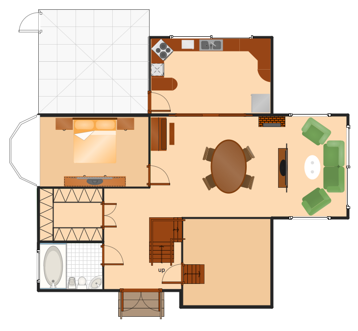
Create Floor Plan
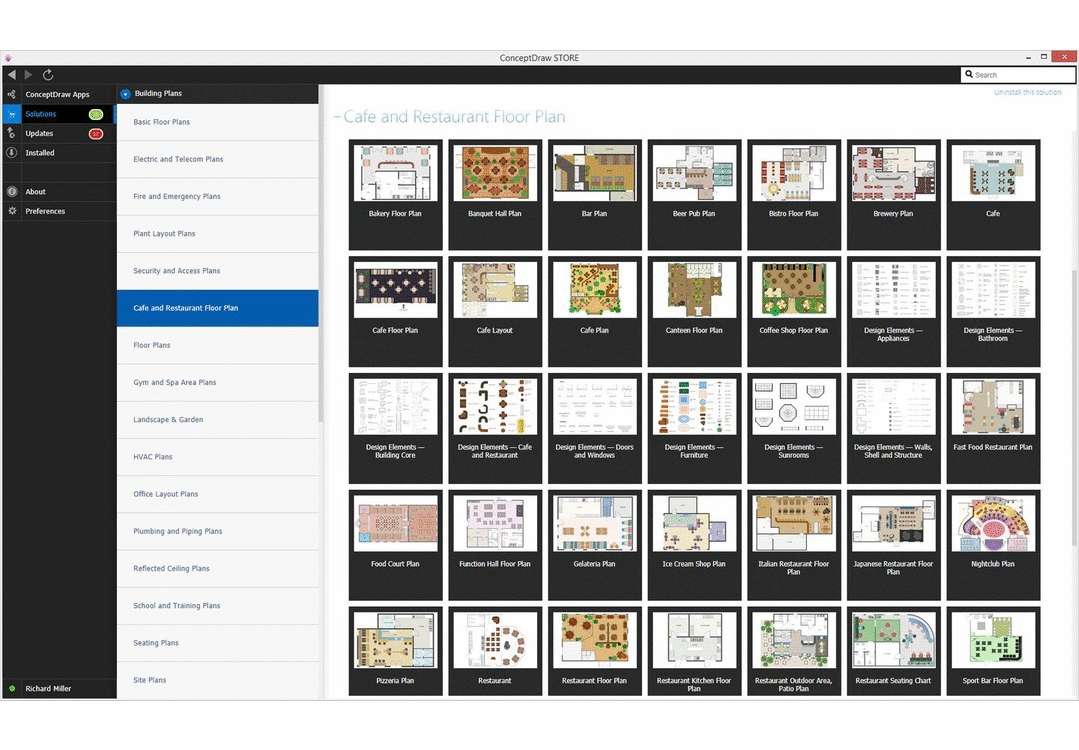
How to create Cafe Floor Plan Design
This cafe electrical floor plan sample shows the outlet and switch layout.
"An electrical drawing, is a type of technical drawing that shows information about power, lighting, and communication for an engineering or architectural project. Any electrical working drawing consists of "lines, symbols, dimensions, and notations to accurately convey an engineering's design to the workers, who install the electrical system on the job".
A complete set of working drawings for the average electrical system in large projects usually consists of:
(1) A plot plan showing the building's location and outside electrical wiring.
(2) Floor plans showing the location of electrical systems on every floor.
(3) Power-riser diagrams showing panel boards.
(4) Control wiring diagrams.
(5) Schedules and other information in combination with construction drawings.
Electrical drafters prepare wiring and layout diagrams used by workers who erect, install, and repair electrical equipment and wiring in communication centers, power plants, electrical distribution systems, and buildings." [Electrical drawing. Wikipedia]
The outlet and switch layout example "Cafe electrical floor plan" was created using the ConceptDraw PRO diagramming and vector drawing software extended with the Electric and Telecom Plans solution from the Building Plans area of ConceptDraw Solution Park.
Outlet and switch layout

Create Floor Plans Easily with ConceptDraw DIAGRAM


- Kinds Of Wall Symbol In Floor Plan
- Curtain Wall Symbol And Floor Plan Symbols
- Glass Wall Floor Plan Symbol
- Glass Wall On Floor Plan
- Floor Plan Symbol Of A Shelf
- Room Divider Floor Plan Symbol
- Half Wall Floor Plan Symbol
- Symbol Of Electrical Wiring Wall Bracket
- Design elements - Walls , shell and structure | Air Curtain Symbol
- Load Bearing Wall Symbol