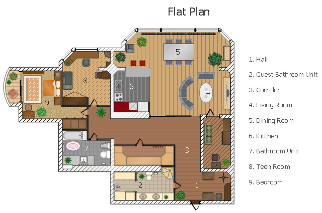
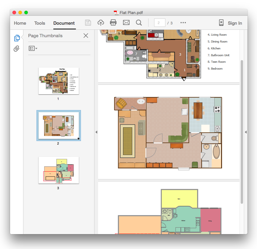
This flat design floor plan sample shows layout of furniture, kitchen equipment and bathroom appliance.
"An apartment (in American English) or flat in British English is a self-contained housing unit (a type of residential real estate) that occupies only part of a building. Such a building may be called an apartment building, apartment house (in American English), block of flats, tower block, high-rise or, occasionally mansion block (in British English), especially if it consists of many apartments for rent. In Scotland it is often called a tenement, which has a pejorative connotation elsewhere. Apartments may be owned by an owner/ occupier by leasehold tenure or rented by tenants (two types of housing tenure).
Apartments can be classified into several types. In North America the typical terms are a studio, efficiency or bachelor apartment (bedsit in the UK). These all tend to be the smallest apartments with the cheapest rents in a given area. This kind of apartment usually consists mainly of a large room which is the living, dining and bedroom combined. There are usually kitchen facilities as part of this central room, but the bathroom is a separate, smaller room.
Moving up from the bachelors/ efficiencies are one-bedroom apartments, in which one bedroom is separate from the rest of the apartment. Then there are two-bedroom, three-bedroom, etc. apartments. Small apartments often have only one entrance.
Large apartments often have two entrances, perhaps a door in the front and another in the back. Depending on the building design, the entrance doors may be directly to the outside or to a common area inside, such as a hallway. Depending on location, apartments may be available for rent furnished with furniture or unfurnished into which a tenant moves in with their own furniture." [Apartment. Wikipedia]
The example "Flat design floor plan" was created using the ConceptDraw PRO diagramming and vector drawing software extended with the Floor Plans solution from the Building Plans area of ConceptDraw Solution Park.
The vector stencils library "Network layout floorplan" contain 34 symbol icons for drawing computer network floor plans and communication equipment and cabling layouts.
"Networking hardware may also be known as network equipment or computer networking devices. Units which are the last receiver or generate data are called hosts or data terminal equipment.
All these terms refer to devices facilitating the use of a computer network. Specifically, they mediate data in a computer network. ...
Typically, networking hardware includes gateways, routers, network bridges, switches, hubs, and repeaters. But it also includes hybrid network devices such as multilayer switches, protocol converters, bridge routers, proxy servers, firewalls, network address translators, multiplexers, network interface controllers, wireless network interface controllers, modems, ISDN terminal adapters, line drivers, wireless access points, networking cables and other related hardware.
The most common kind of networking hardware today is a copper-based Ethernet adapter because of its standard inclusion on most modern computer systems. Wireless networking has, however, become increasingly popular, especially for portable and handheld devices.
Other hardware prevalent in computer networking includes data center equipment (such as file servers, database servers and storage areas), network services (such as DNS, DHCP, email, etc.) as well as devices which assure content delivery." [Networking hardware. Wikipedia]
The shapes example "Design elements - Network layout floorplan" was created using the ConceptDraw PRO diagramming and vector drawing software extended with the Network Layout Floor Plans solution from the Computer and Networks area of ConceptDraw Solution Park.
HelpDesk
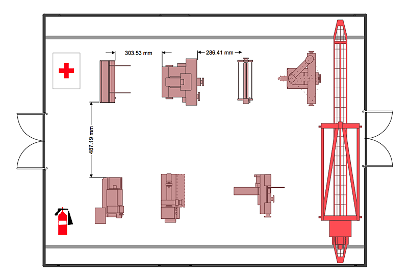
How to Create a Plant Layout Design
A plant construction process begins from a plant layout stage - an engineering stage used to design, analyze and finally choose the suitable configurations for a manufacturing plant. Plant Layout issues are core to any enterprise and are challenged in all types of manufacturing process. The sufficiency of layout influences the efficiency of subsequent operations. It is an important background for efficient manufacturing and also has a great deal with many questions. Once the place of the plant has been determined, the next important task before the management of the plant is to plan appropriate layout for the enterprise. Plant layout is used to create the most effective physical arrangement of machinery and equipment, with the plant building in such a manner so as to make quickest and cheapest way from a raw material to the shipment of the completed product Making a plan that shows the location of industrial equipment involves many different elements that can be managed using ConHelpDesk
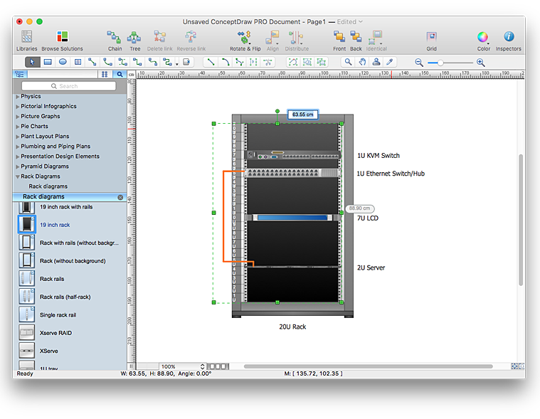
How to Resize Objects in ConceptDraw PRO
When creating diagram using ConceptDraw PRO, you can select, move, resize and rotate objects. After selecting an object (or objects) in a document, you can change it position, resize it or move an object to the desired position. The sizes of objects in ConceptDraw PRO can be changed by simple dragging, or you can set a particular size of any object. Using ConceptDraw PRO, you can re-size an object on the page using the absolute measurements instead of a mouse. You can make quick work of designing complex drawing using a combination of different-sized items.The vector stencils library "Lighting" contains 55 symbols of lighting devices and equipment.
Use these shapes for drawing lighting design floor plans, circuit schematic and wiring diagrams, cabling layouts, and reflected ceiling plans in the ConceptDraw PRO diagramming and vector drawing software.
The vector stencils library "Lighting" is included in the Electric and Telecom Plans solution from the Building Plans area of ConceptDraw Solution Park.
The vector stencils library "Electrical and telecom" contains 83 symbols of electrical and telecommunication equipment.
Use these shapes for drawing electrical and telecom system design floor plans, cabling layout schemes, and wiring diagrams in the ConceptDraw PRO diagramming and vector drawing software.
The vector stencils library "Electrical and telecom" is included in the Electric and Telecom Plans solution from the Building Plans area of ConceptDraw Solution Park.
 HVAC Plans
Use HVAC Plans solution to create professional, clear and vivid HVAC-systems design plans, which represent effectively your HVAC marketing plan ideas, develop plans for modern ventilation units, central air heaters, to display the refrigeration systems for automated buildings control, environmental control, and energy systems.
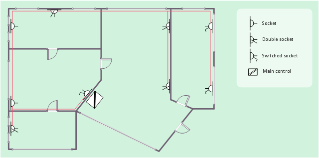
This electrical floot plan sample shows the Power socket outlet layout.
"The term plug is in general and technical use in all forms of English, common alternatives being power plug, electric plug, and (in the UK) plug top. The normal technical term (in both British and International English) for an AC power socket is socket-outlet, but in non-technical common use a number of other terms are used. In British English the general term is socket, but there are numerous common alternatives, including power point, plug socket, wall socket, and wall plug. In American English receptacle and outlet are common, sometimes with qualifiers such as wall outlet, electrical outlet and electrical receptacle, all of these sometimes to be found in the same document. A socket may be surrounded by a decorative and/ or protective cover called a wall plate, face plate, outlet cover, socket cover, or wall cover. In some designs this is an integral piece with the socket itself, bought and installed as a single unit." [AC power plugs and sockets. Wikipedia]
The electrical floot plan example "Power socket outlet layout" was created using the ConceptDraw PRO diagramming and vector drawing software extended with the Electric and Telecom Plans solution from the Building plans area of ConceptDraw Solution Park.
HelpDesk
How To Convert a Floor Plan to Adobe PDF Using ConceptDraw PRO
ConceptDraw PRO allows you to easy share your building plans between different computers with different operating systems and applications using it's export capabilities.You can get clear floor plan in pdf format and avoid any problems while communicating it with your Customers and Contractors.- How To use House Electrical Plan Software | Design elements ...
- Flat design floor plan | Building Plan Software . Building Plan ...
- Hold Open Unit
- How To use House Electrical Plan Software | Design elements ...
- Symbol Plan Of A Built In Wall Units
- How To use Kitchen Design Software | How to Draw a Flat ...
- How To use House Electrical Plan Software | Electrical and telecom ...
- Cabinets and bookcases - Vector stencils library | Cabinet Design ...
- How To use Landscape Design Software | How To Create Home ...
- CAD Drawing Software for Making Mechanic Diagram and Electrical ...
- Flat design floor plan | How To use Kitchen Design Software | Create ...
- How To use House Electrical Plan Software | Design elements ...
- How To use House Electrical Plan Software | Interior Design Office ...
- Office furniture - Vector stencils library | Building Drawing Software ...
- Lighting and switch layout | Lighting and switch layout | Design ...
- Cabinet Design Software | Cabinets and bookcases - Vector stencils ...
- How To use House Electrical Plan Software | Design elements ...
- Rack Diagrams | Network Diagramming Software for Design Rack ...
- Cabinet Design Software | Interior Design Software . Building Plan ...
- How To use House Electrical Plan Software | How To Create ...
