- Electric and Telecom Plans Free
- Fire and Emergency Plans Free
- Floor Plans Free
- Plant Layout Plans Free
- School and Training Plans Free
- Seating Plans Free
- Security and Access Plans Free
- Site Plans Free
- Sport Field Plans Free
- Business Process Diagrams Free
- Business Process Mapping Free
- Classic Business Process Modeling Free
- Cross-Functional Flowcharts Free
- Event-driven Process Chain Diagrams Free
- IDEF Business Process Diagrams Free
- Logistics Flow Charts Free
- Workflow Diagrams Free
- ConceptDraw Dashboard for Facebook Free
- Mind Map Exchange Free
- MindTweet Free
- Note Exchange Free
- Project Exchange Free
- Social Media Response Free
- Active Directory Diagrams Free
- AWS Architecture Diagrams Free
- Cisco Network Diagrams Free
- Cisco Networking Free
- Cloud Computing Diagrams Free
- Computer Network Diagrams Free
- Google Cloud Platform Free
- Interactive Voice Response Diagrams Free
- Network Layout Floor Plans Free
- Network Security Diagrams Free
- Rack Diagrams Free
- Telecommunication Network Diagrams Free
- Vehicular Networking Free
- Wireless Networks Free
- Comparison Dashboard Free
- Composition Dashboard Free
- Correlation Dashboard Free
- Frequency Distribution Dashboard Free
- Meter Dashboard Free
- Spatial Dashboard Free
- Status Dashboard Free
- Time Series Dashboard Free
- Basic Circle-Spoke Diagrams Free
- Basic Circular Arrows Diagrams Free
- Basic Venn Diagrams Free
- Block Diagrams Free
- Concept Maps Free
- Family Tree Free
- Flowcharts Free
- Basic Area Charts Free
- Basic Bar Graphs Free
- Basic Divided Bar Diagrams Free
- Basic Histograms Free
- Basic Line Graphs Free
- Basic Picture Graphs Free
- Basic Pie Charts Free
- Basic Scatter Diagrams Free
- Aerospace and Transport Free
- Artwork Free
- Audio, Video, Media Free
- Business and Finance Free
- Computers and Communications Free
- Holiday Free
- Manufacturing and Maintenance Free
- Nature Free
- People Free
- Presentation Clipart Free
- Safety and Security Free
- Audio and Video Connectors Free
- Basic Circuit Diagrams Free
- Chemical and Process Engineering Free
- Digital Electronics Free
- Electrical Engineering Free
- Electron Tube Circuits Free
- Fault Tree Analysis Diagrams Free
- GHS Hazard Pictograms Free
- Home Automation and Wiring Free
- Mechanical Engineering Free
- Specification and Description Language (SDL) Free
- Transport Hazard Pictograms Free
- Data-driven Infographics Free
- Pictorial Infographics Free
- Spatial Infographics Free
- Typography Infographics Free
- Calendars Free
- Decision Making Free
- Enterprise Architecture Diagrams Free
- Fishbone Diagrams Free
- Organizational Charts Free
- Plan-Do-Check-Act (PDCA) Free
- Seven Management and Planning Tools Free
- SWOT and TOWS Matrix Diagrams Free
- Timeline Diagrams Free
- Australia Map Free
- Continent Maps Free
- Directional Maps Free
- Germany Map Free
- Metro Map Free
- UK Map Free
- USA Maps Free
- Customer Journey Mapping Free
- Marketing Diagrams Free
- Matrices Free
- Pyramid Diagrams Free
- Sales Dashboard Free
- Sales Flowcharts Free
- Target and Circular Diagrams Free
- Cash Flow Reports Free
- Current Activities Reports Free
- Custom Excel Report Free
- Knowledge Reports Free
- MINDMAP Reports Free
- Overview Reports Free
- PM Agile Free
- PM Dashboards Free
- PM Docs Free
- PM Easy Free
- PM Meetings Free
- PM Planning Free
- PM Presentations Free
- PM Response Free
- Resource Usage Reports Free
- Visual Reports Free
- House of Quality Free
- Quality Mind Map Free
- Total Quality Management TQM Diagrams Free
- Value Stream Mapping Free
- Android User Interface Free
- Data Flow Diagrams (DFD) Free
- Entity-Relationship Diagram (ERD) Free
- EXPRESS-G data Modeling Diagram Free
- IDEF0 Diagrams Free
- iPhone User Interface Free
- Jackson Structured Programming (JSP) Diagrams Free
- macOS User Interface Free
- Object-Role Modeling (ORM) Diagrams Free
- Rapid UML Free
- SYSML Free
- Website Wireframe Free
- Windows 10 User Interface Free
Cisco Networking
The Cisco Systems Company is a leader in production the multifarious network equipment, switches, routers, wireless communication devices, unified communications, video conferencing, means of network security and management. The high quality, reliability and functionality, advanced production technologies and unique features allowed the Cisco network equipment to gain the trust and love of many users all over the world.
The Cisco network equipment provides many series of devices including several devices' models that differ in their characteristics. The use of them helps in easy building the networks of different scale and purpose. The Cisco equipment allows creating the enterprise managed wireless networks of any complexity using the latest security standards.
Before proceeding to the equipment installation and connection various devices into a single system, it is recommended to not only thought-out the system's configuration, but also design its schematic. Having the detailed scheme, you can immediately start linking devices into the network, configuring switches and routers, connecting the network to the global network, and ensuring its security.
Cisco Networking solution extends the ConceptDraw DIAGRAM software functionality with properties of network diagramming and network modeling software. Solution provides the multifarious samples and large quantity of libraries with incredibly huge amount of complex predesigned vector design elements of standardized Cisco devices and equipment, such as CISCO servers, Cisco switches, Cisco Fabric Interconnects, Cisco Gateways, Access Servers, Cisco Optical NCS 1000, Cisco Optical NCS 2000, Cisco Optical NCS 4000, and Cisco Optical NCS 4200 devices, Cisco Physical Security, Cisco Service Exchange, Cisco Storage Networking, Cisco Unified Communications, Cisco Video, Cisco Wireless, and Cisco Application Networking Services equipment.
It is the best solution for the network administrators, network engineers and other IT professionals responsible for building, maintenance and administration of networks, allowing them to design Cisco computer network schematics, Models of the network devices’ interaction, Schemes of networks construction, of installation and configuration the Cisco equipment, Network infrastructure schematics, Cisco network designs, Network topology diagrams, Diagrams of managing network devices and ensuring security of network structures, facilitating search and elimination of troubleshoots in managed networks of the small and medium enterprises.
-
Install this solution Free -
What I need to get started -
Solution Requirements - This solution requires the following products to be installed:
ConceptDraw DIAGRAM v18 - This solution requires the following products to be installed:
-
Compatibility - Sonoma (14), Sonoma (15)
MS Windows 10, 11 - Sonoma (14), Sonoma (15)
-
Support for this Solution -
Helpdesk
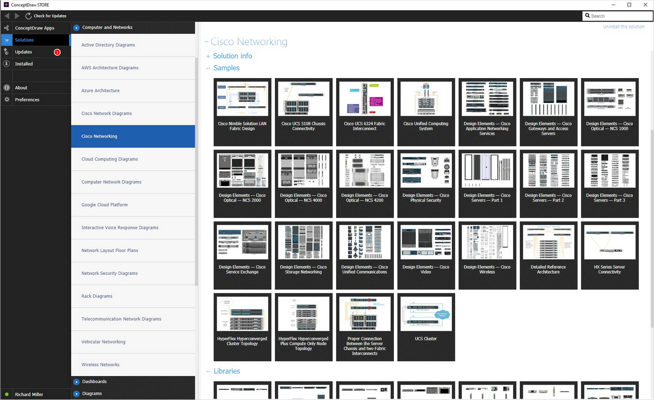
This solution contains 10 examples and 13 libraries containing 609 vector graphics, to allow you to create professional looking documents.
Design Elements — Cisco Application Networking Services
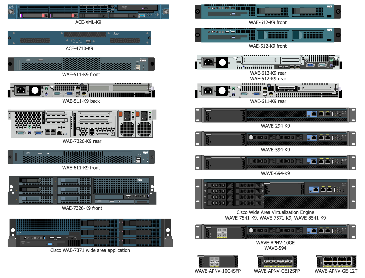
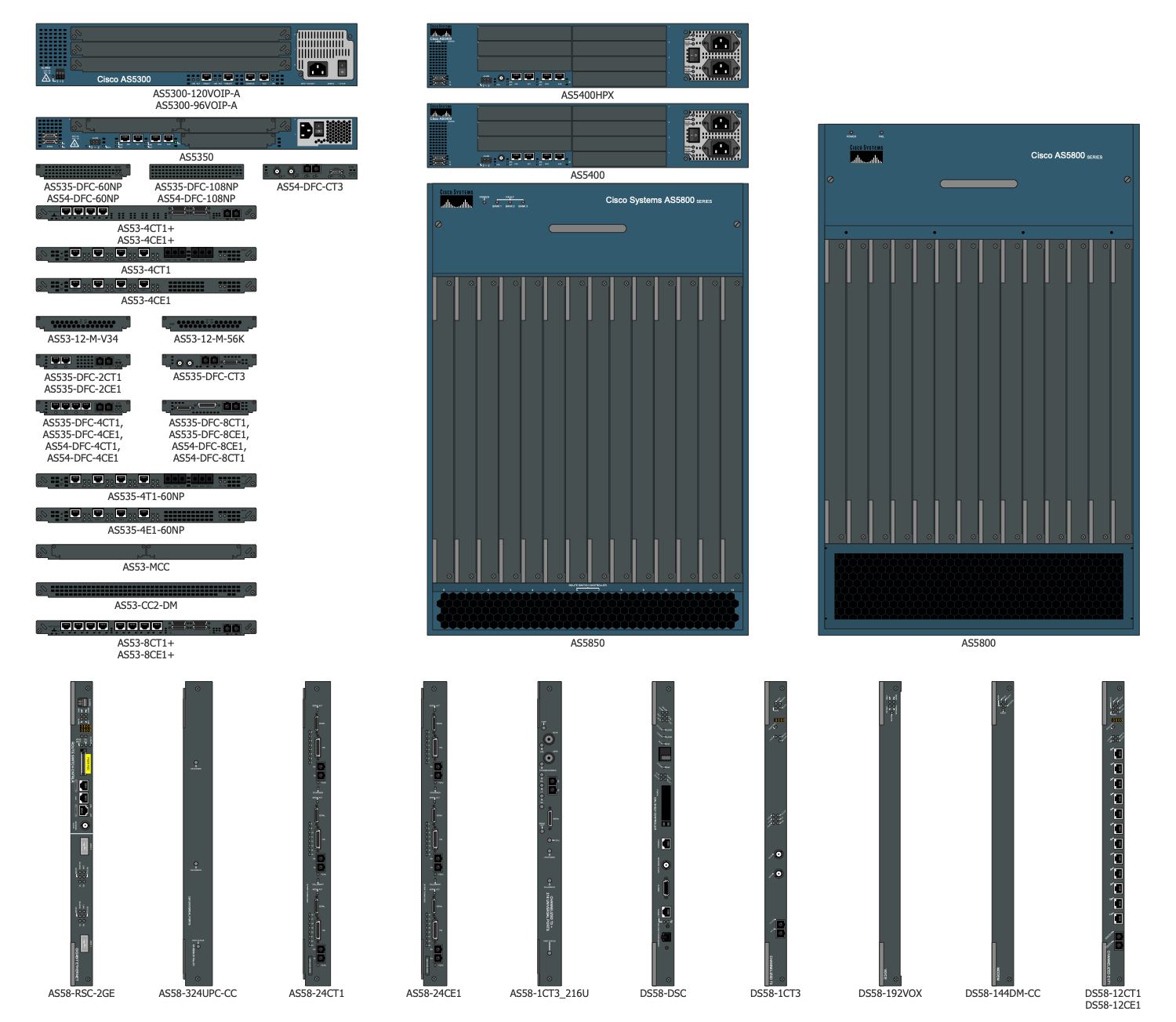
Design Elements — Cisco Gateways and Access Servers
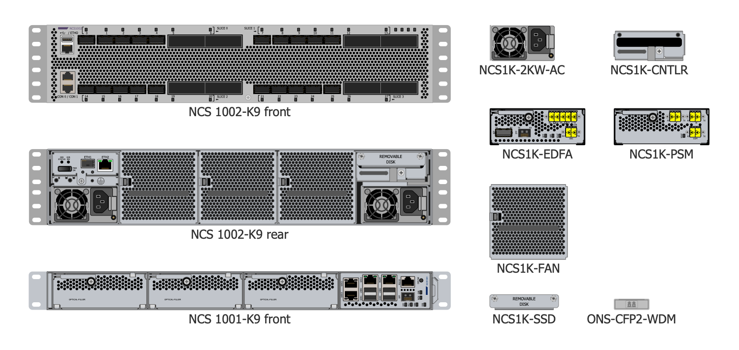
Design Elements — Cisco Optical NCS 1000
Design Elements — Cisco Optical NCS 2000
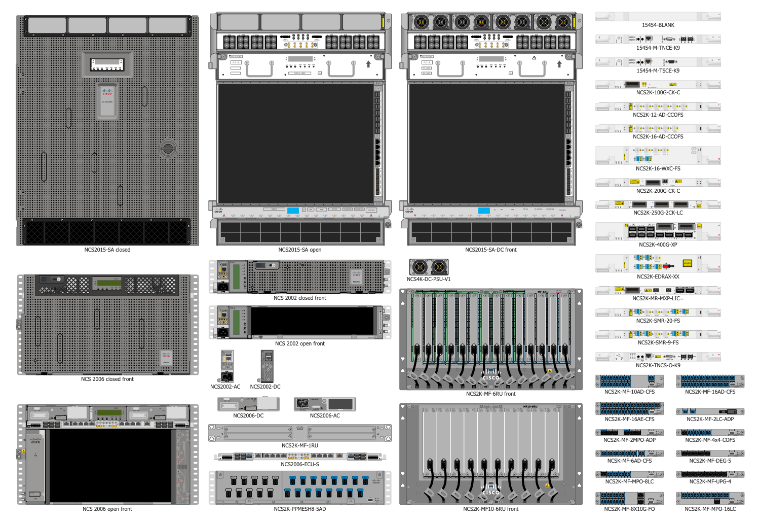
Design Elements — Cisco Optical NCS 4000
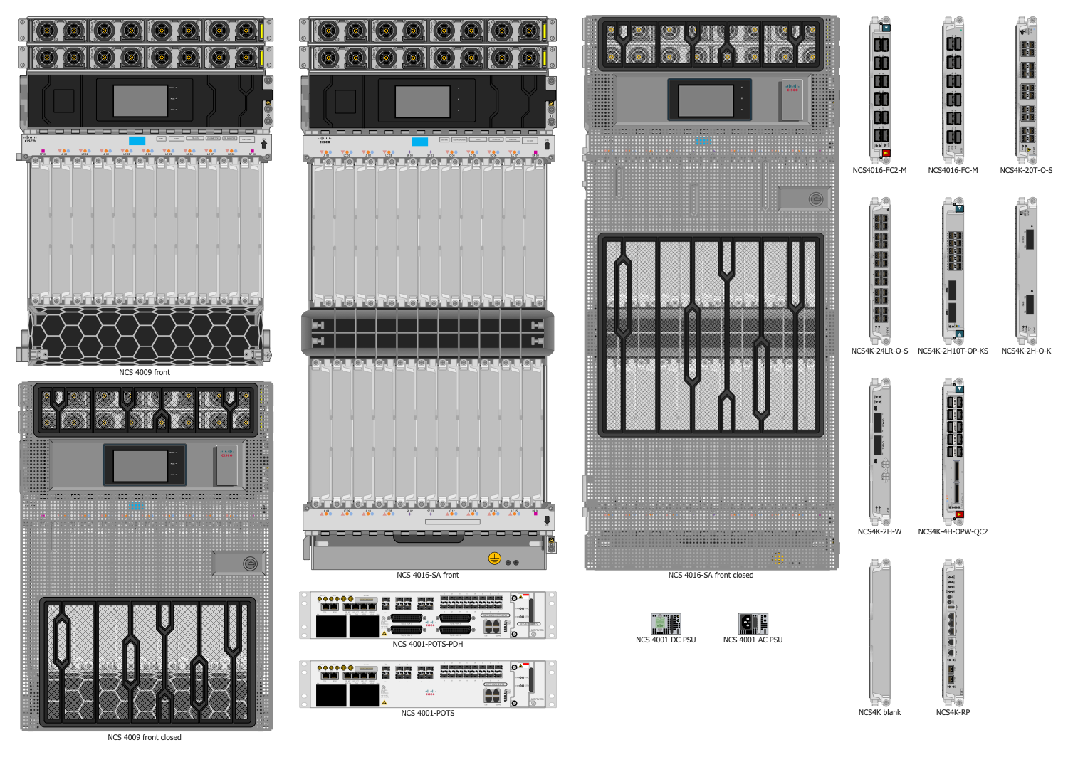
Design Elements — Cisco Optical NCS 4200
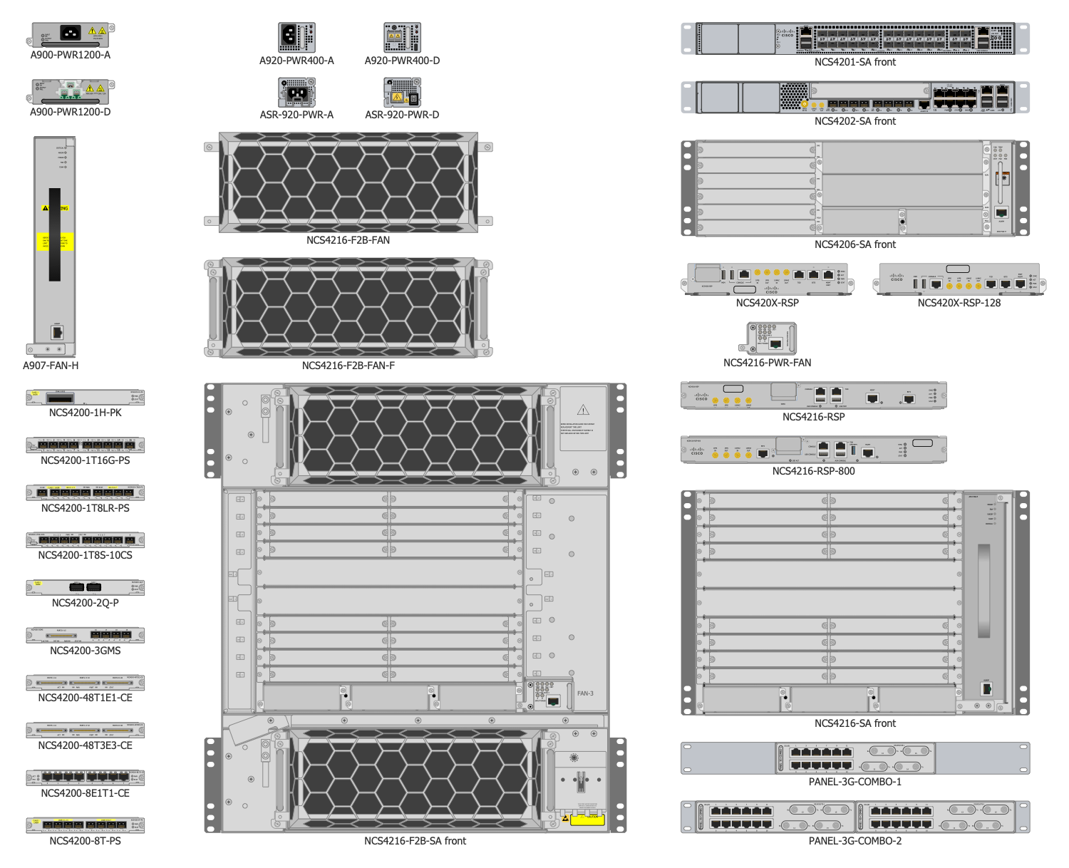
Design Elements — Cisco Physical Security
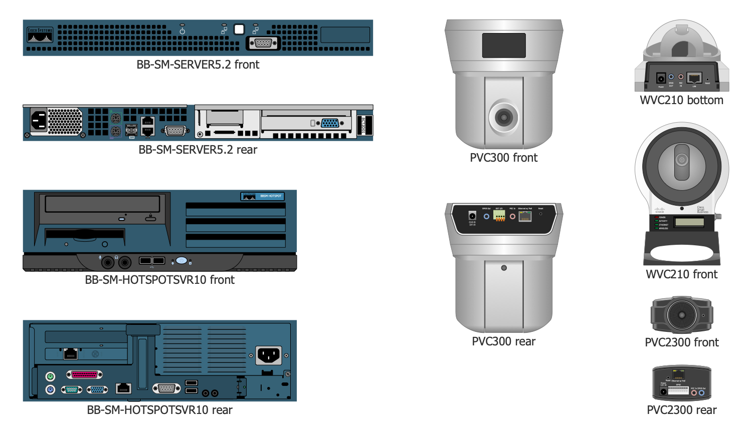
Design Elements — Cisco Servers, Part 1
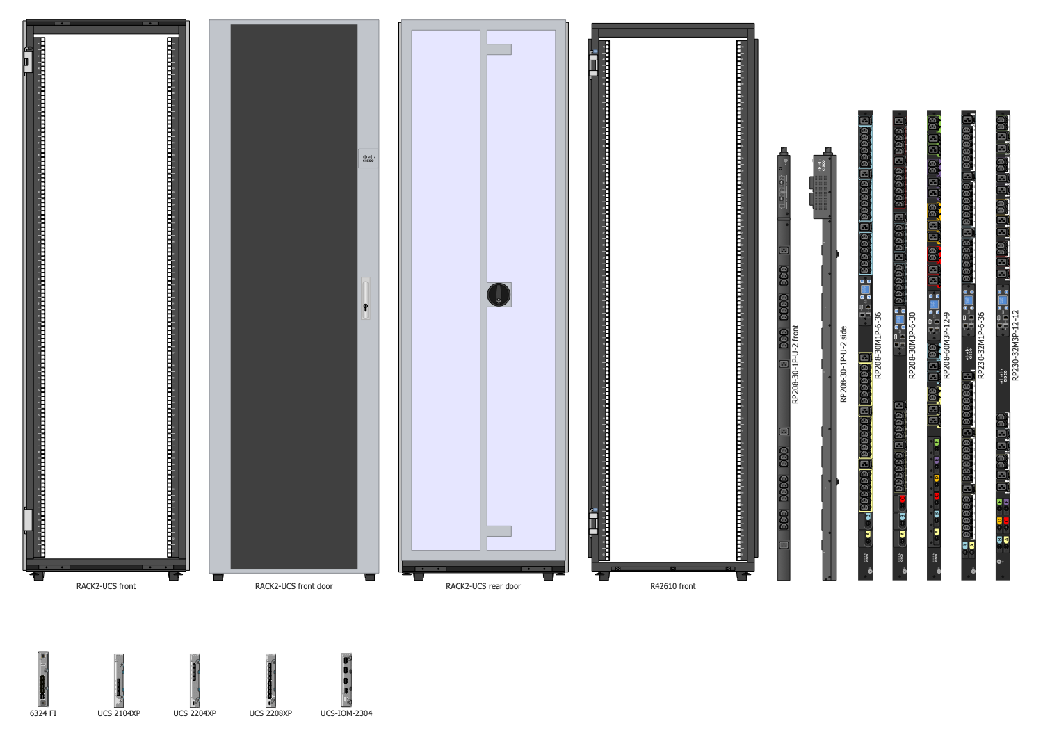
Design Elements — Cisco Servers, Part 2
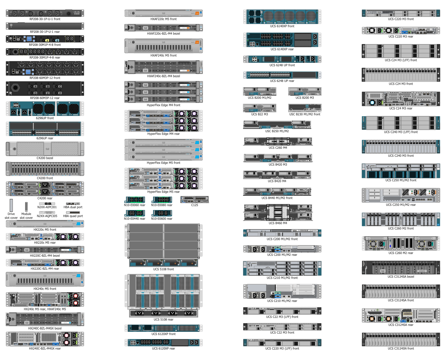
Design Elements — Cisco Servers, Part 3
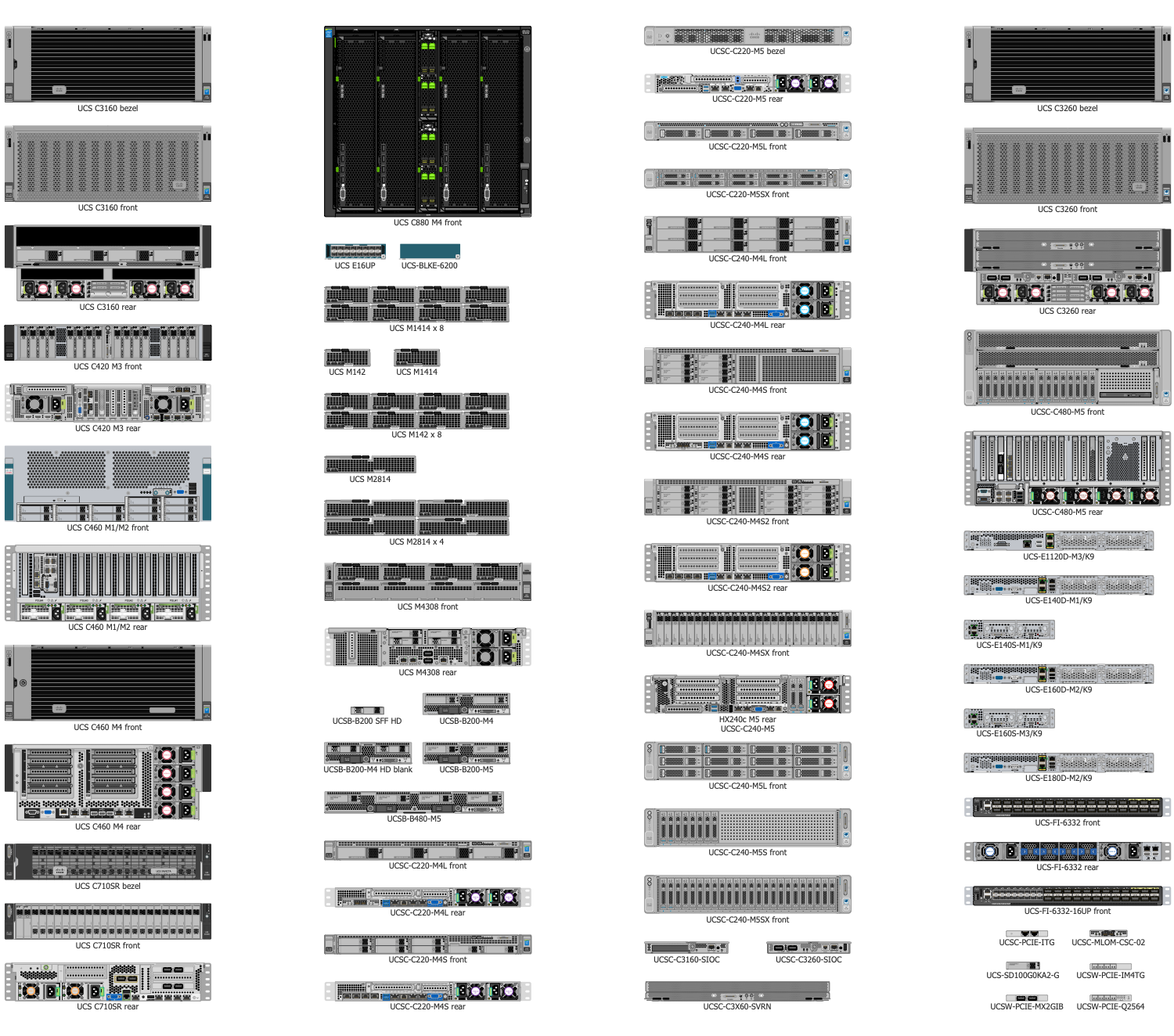
Design Elements — Cisco Service Exchange
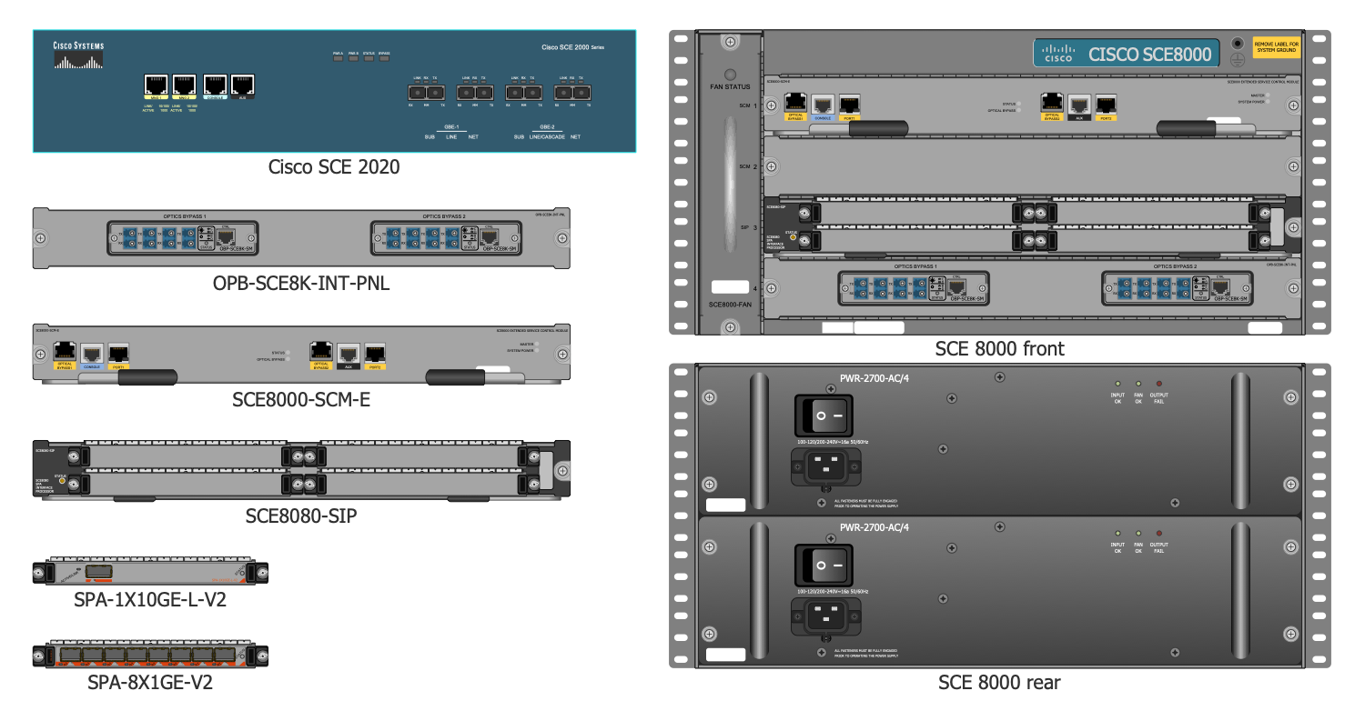
Design Elements — Cisco Storage Networking
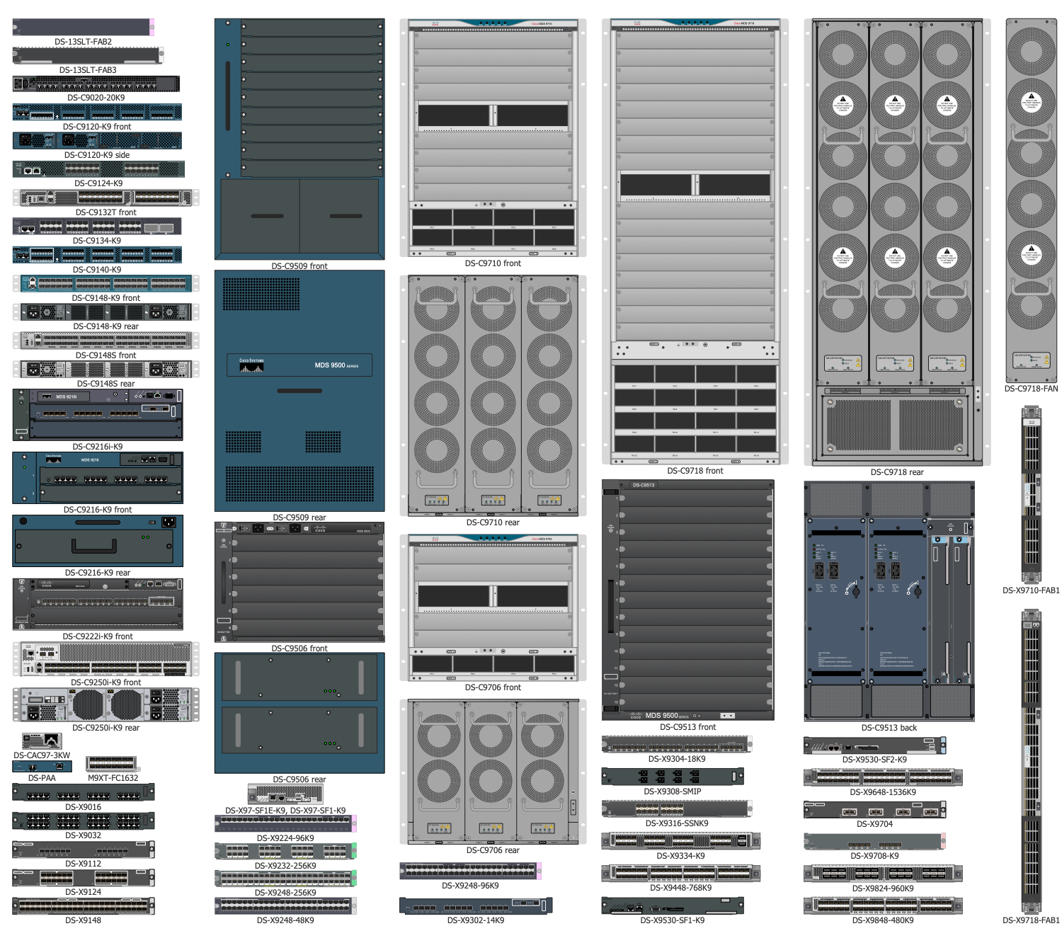
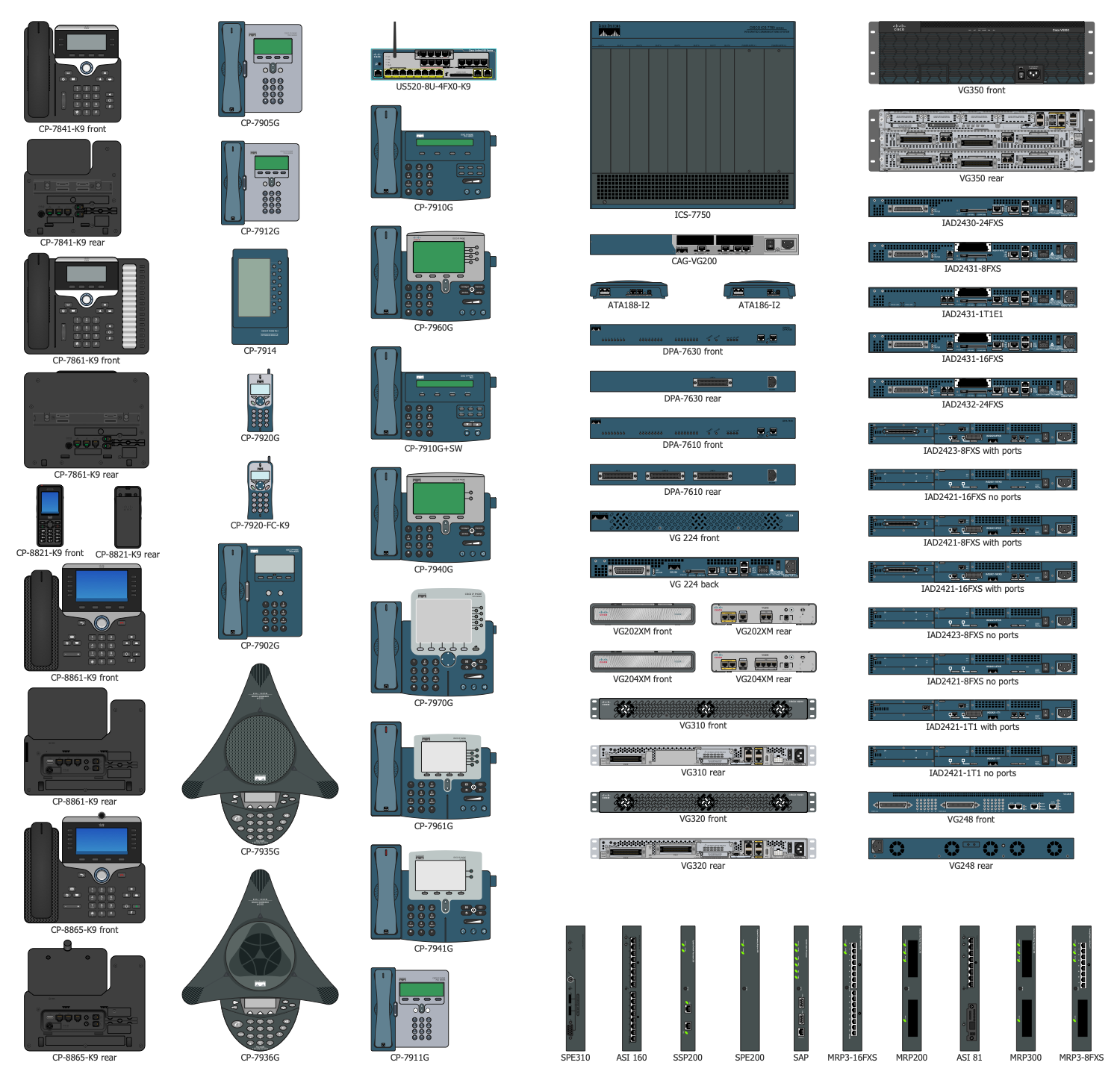
Design Elements — Cisco Unified Communications
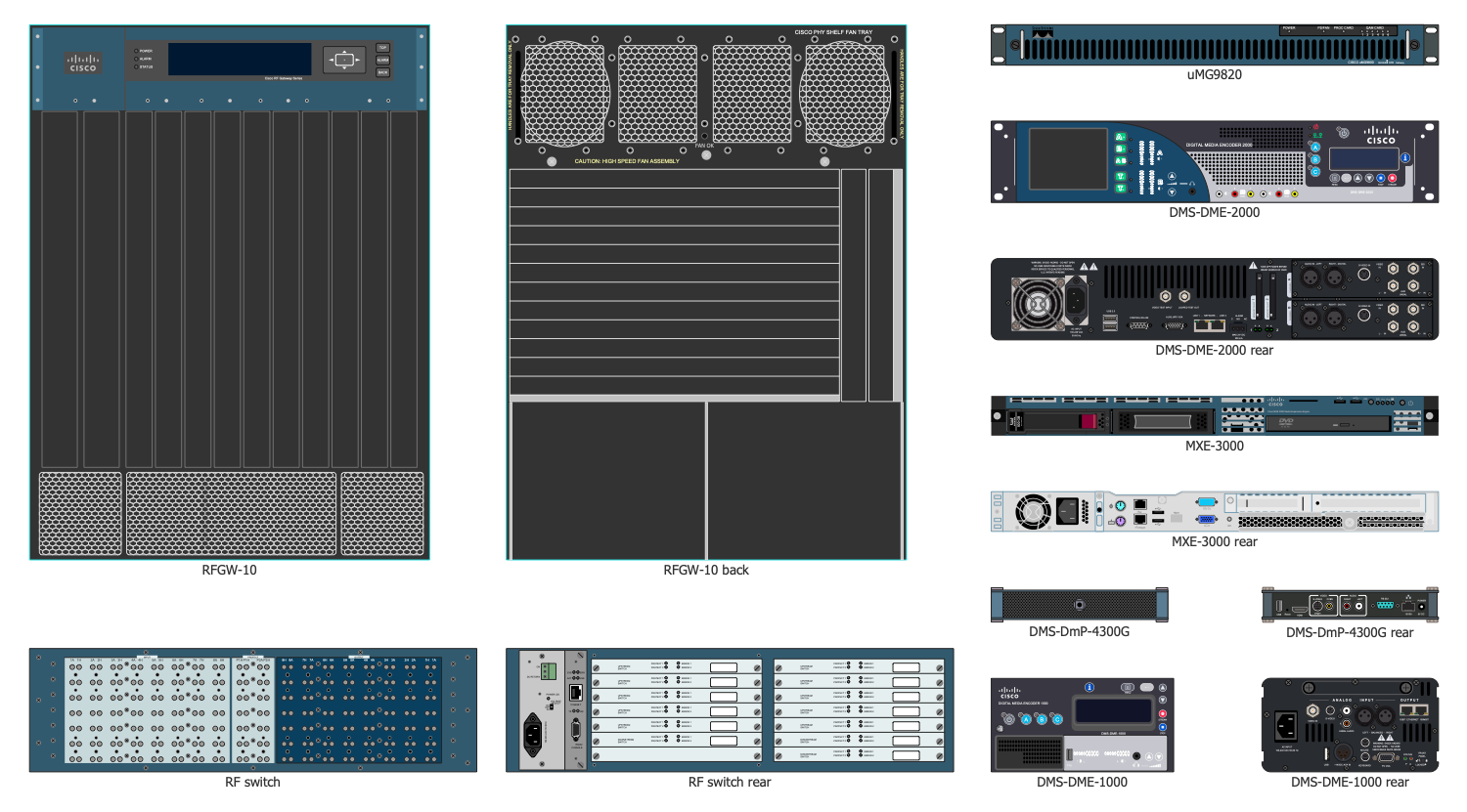
Design Elements — Cisco Video
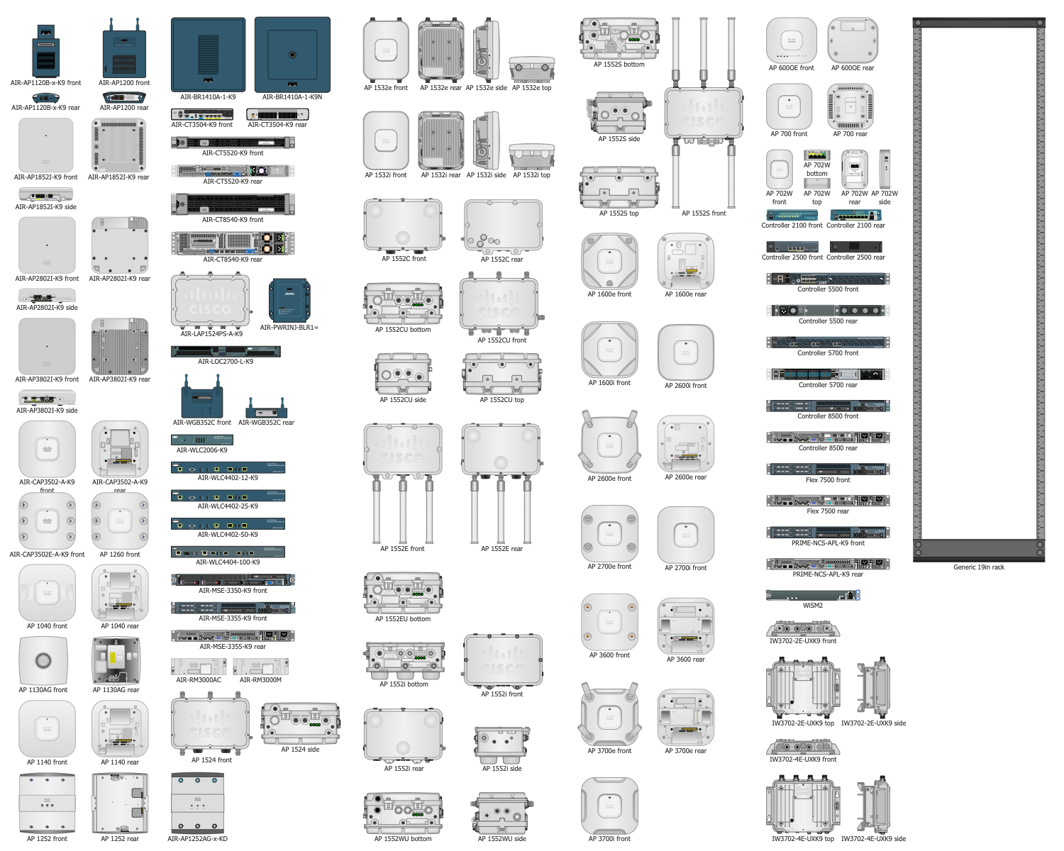
Design Elements — Cisco Wireless
Examples
There are a few samples that you see on this page which were created in the ConceptDraw DIAGRAM application by using the Cisco Networking solution. Some of the solution's capabilities as well as the professional results which you can achieve are all demonstrated here on this page.
All source documents are vector graphic documents which are always available for modifying, reviewing and/or converting to many different formats, such as MS PowerPoint, PDF file, MS Visio, and many other graphic ones from the ConceptDraw Solution Park or ConceptDraw STORE. The Cisco Networking solution is available to all ConceptDraw DIAGRAM users to get installed and used while working in the ConceptDraw DIAGRAM diagramming and drawing software.
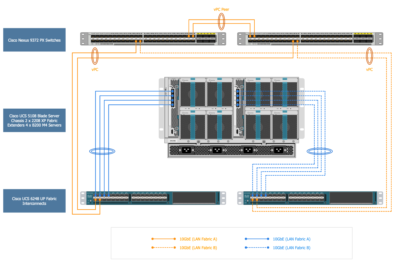
Example 1: Cisco Nimble Solution LAN Fabric Design
This diagram was created in ConceptDraw DIAGRAM using the composition of libraries from the Cisco Networking Solution. An experienced user spent 10 minutes creating this sample.
This sample represents the Cisco Nimble Solution LAN Fabric Design. It is a connectivity diagram created on the base of "Cisco-Nimble Solution LAN Fabric Design" illustration for the article "Cisco-Nimble Solution on Cisco UCS and Nimble AF5000 with Citrix XenDesktop 7.11VDI 5000 Seat Deployment with Graphics Support". This LAN network provides the network attainability to the applications that are hosted on the Cisco UCS servers in data centers. The presented infrastructure includes two Cisco Nexus 9372 PX Switches that are deployed in NX-OS standalone mode, the Cisco UCS 5108 Blade Server, Chassis 2x2208 XP Fabric, Extenders 4xB200 M4 Severs, and two Cisco UCS 6248 UP Fabric Interconnects. The Cisco Nexus switches use the Virtual Port Channels (vPCs) and are connected to the ports on the Cisco Fabric Interconnects with the 10Gbps links. The bandwidth of 20Gbps is provided through the Nexus switches, the VLAN trunking is switched on the links, the jumbo frames are also available.
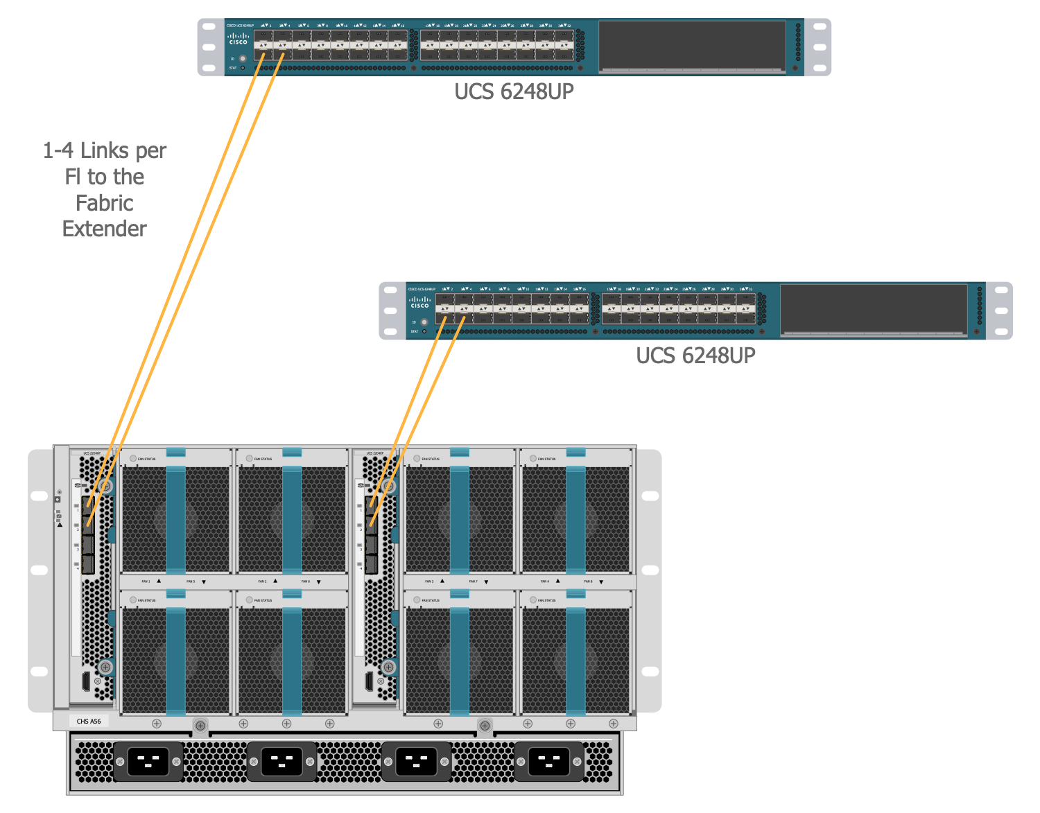
Example 2: Cisco UCS 5108 Chassis Connectivity
This diagram was created in ConceptDraw DIAGRAM using the composition of libraries from the Cisco Networking Solution. An experienced user spent 5 minutes creating this sample.
This Cisco networking diagram shows the connectivity diagram sample designed basing on the "Cisco UCS 5108 Chassis Connectivity" image published as an illustration for the article "Cisco HyperFlex Hyperconverged System with 1000 XenDesktop 7 Seats". The Cisco HyperFlex is a system that includes the communication pathways falling into four defined zones, such as the Management Zone, VM Zone, Storage Zone, and VMotion Zone. The Cisco UCS 5108 server chassis is the base for deployment the Cisco unified computing platforms, the main task of which is to provide a high scalability and configuration flexibility. The Cisco UCS 5108 Chassis supports 40 Gigabit Ethernet ports and the bandwidth of input/output data up to 80 Gbps for each slot of the server. Up to four servers can be installed to it. The 2x Cisco UCS 2208XP extender or FEX installed at the back of the blade chassis is managed as an extender to the Fabric Interconnect switch.
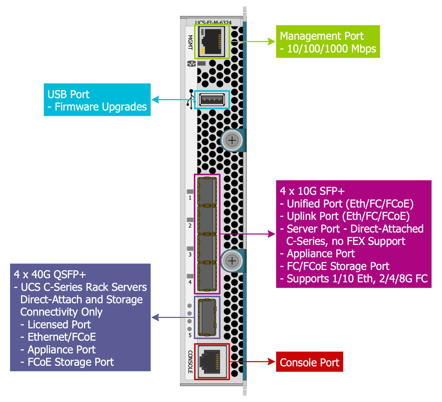
Example 3: Cisco UCS 6324 Fabric Interconnect
This diagram was created in ConceptDraw DIAGRAM using the composition of libraries from the Cisco Networking Solution. An experienced user spent 5 minutes creating this sample.
This connectivity diagram sample demonstrates the structure of the Cisco UCS 6324 Fabric Interconnect. It is based on the same-named figure from the article "FlexPod with Cisco UCS Mini Design Guide" and now is designed by means of ConceptDraw DIAGRAM software tools. The Cisco UCS 6324 Fabric Interconnect looks like a regular switch in servers' chassis and can be installed into the Cisco UCS 5108 instead of the Fabric Extender (FEX). Cisco UCS 6324 Fabric Interconnect lets extend the Cisco UCS architecture to the environment with requirements for the smaller domains. It provides the maximally simplified server-to-server connection and building the 10G Ethernet networks. Being capable to connect from 1 up to 15 servers, even within a limited space, the Cisco UCS 6324 Fabric Interconnect architecture is actively used on the client's territory, in the small offices and branch offices, for construction the models with minimal requirements for remote sites and systems.
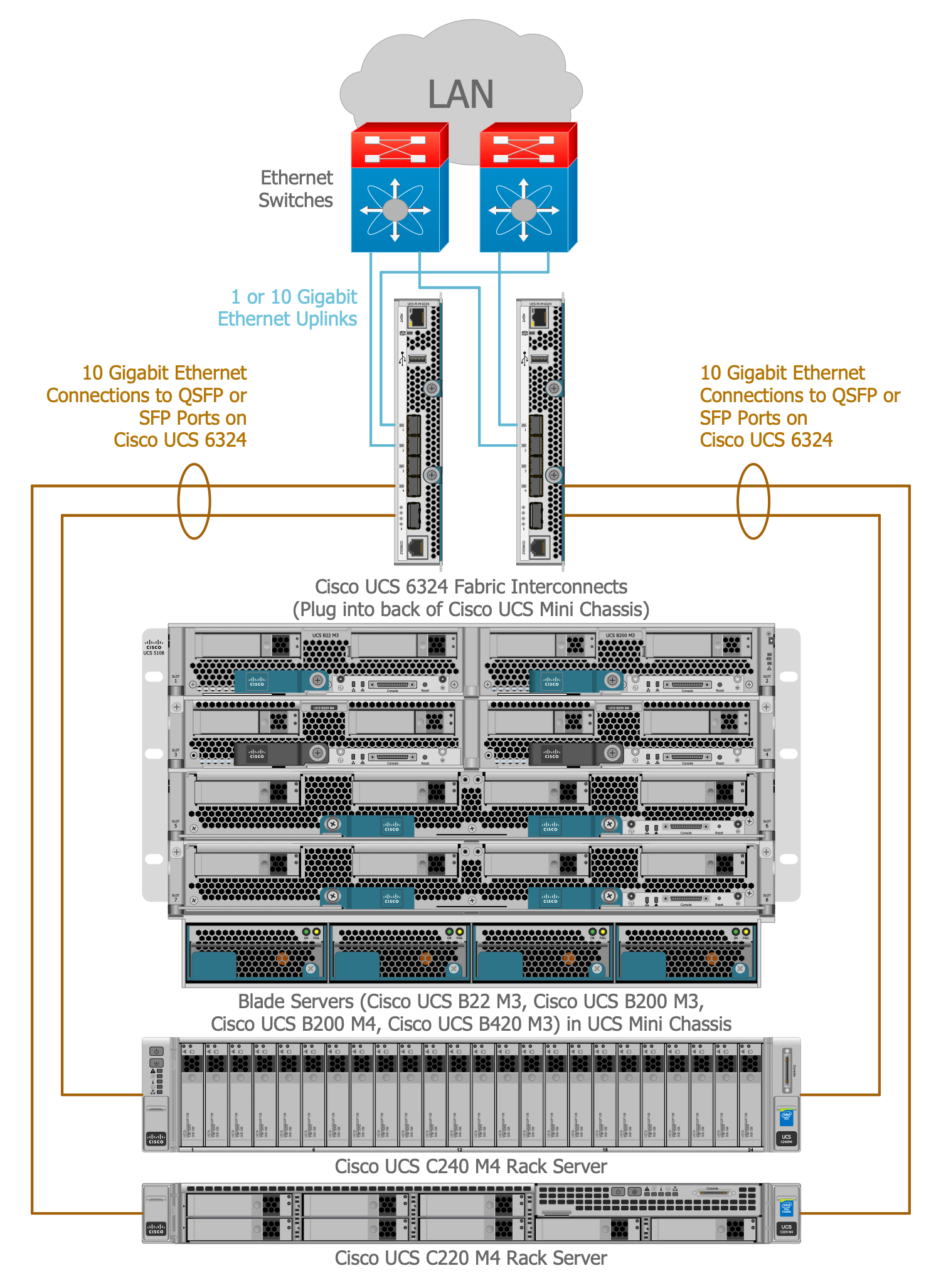
Example 4: Cisco Unified Computing System
This diagram was created in ConceptDraw DIAGRAM using the composition of libraries from the Cisco Networking Solution. An experienced user spent 10 minutes creating this sample.
This sample represents the Cisco Unified Computing System. It was constructed on the base of the "Cisco Unified Computing System is a Highly Available Cohesive Architecture" illustration from the "FlexPod with Cisco UCS Mini Design Guide". The Cisco Unified Computing System or Cisco UCS is a large data center platform of the next generation, which unites together the networking, computing, storage access, and virtualization resources, making a unified cohesive system. It is the best way to reduce the TCO (total cost of ownership) and simultaneously to increase business agility. A given system is a multi-chassis platform, integrated and scalable, all resources of which are shared in a unified management domain. The system works on the x86-architecture servers, has a low-latency and lets constructing a lossless 10 Gigabit Ethernet unified network. The Cisco UCS 6324 Fabric Interconnects are installed at the back of the Cisco UCS Mini Chassis. There are included the blade servers in UCS Mini Chassis and the Rack servers.
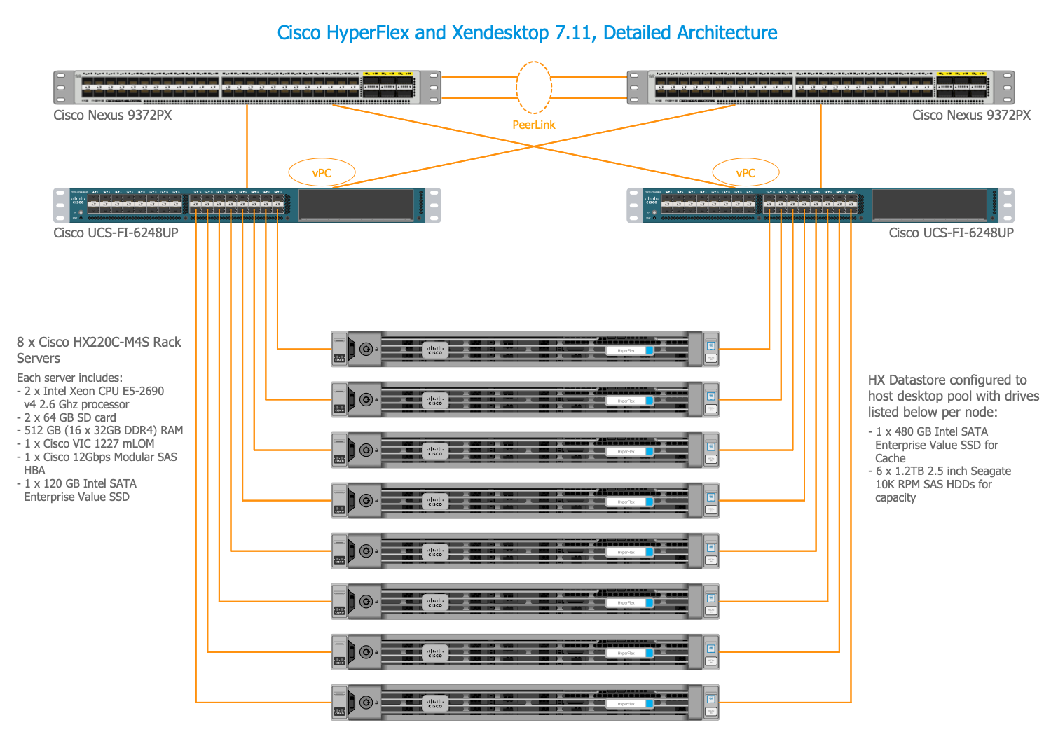
Example 5: Detailed Reference Architecture
This diagram was created in ConceptDraw DIAGRAM using the composition of libraries from the Cisco Networking Solution. An experienced user spent 10 minutes creating this sample.
This diagram sample demonstrates the detailed reference architecture of the Cisco HyperFlex and Xendesktop 7.11. It was designed in ConceptDraw DIAGRAM basing on the image "Detailed reference Architecture with Physical Hardware Cabling Configured to Enable the Solution" illustrating the "Cisco HyperFlex Hyperconverged System with 1000 XenDesktop7 Seats" article. This architecture includes two Cisco Nexus 9372PX Layer 2 Access Switches, two Cisco UCS-FI-6248UP devices, Eight Cisco UCS HX220c-M4S Rack servers with 2 x Intel Xeon CPU E5-2690 v4 2.6 GHz processor, 2 x 64 Gb SD card, 512 Gb (16 x 32 Gb DDR4) RAM, 1 x Cisco VIC 1227 mLOM, 1 x Cisco 12 Gbps Modular SAS HBA, 1 x 120 Gb Intel SATA Enterprise Value SSD, and HX Datastore configured to host desktop pool with drives listed below per node: 1 x 480 Gb Intel SATA Enterprise Value SSD for Cache, 6 x 1.2 Tb 2,5 inch HDDs for capacity.
Example 6: HX Series Server Connectivity
This diagram was created in ConceptDraw DIAGRAM using the composition of libraries from the Cisco Networking Solution. An experienced user spent 5 minutes creating this sample.
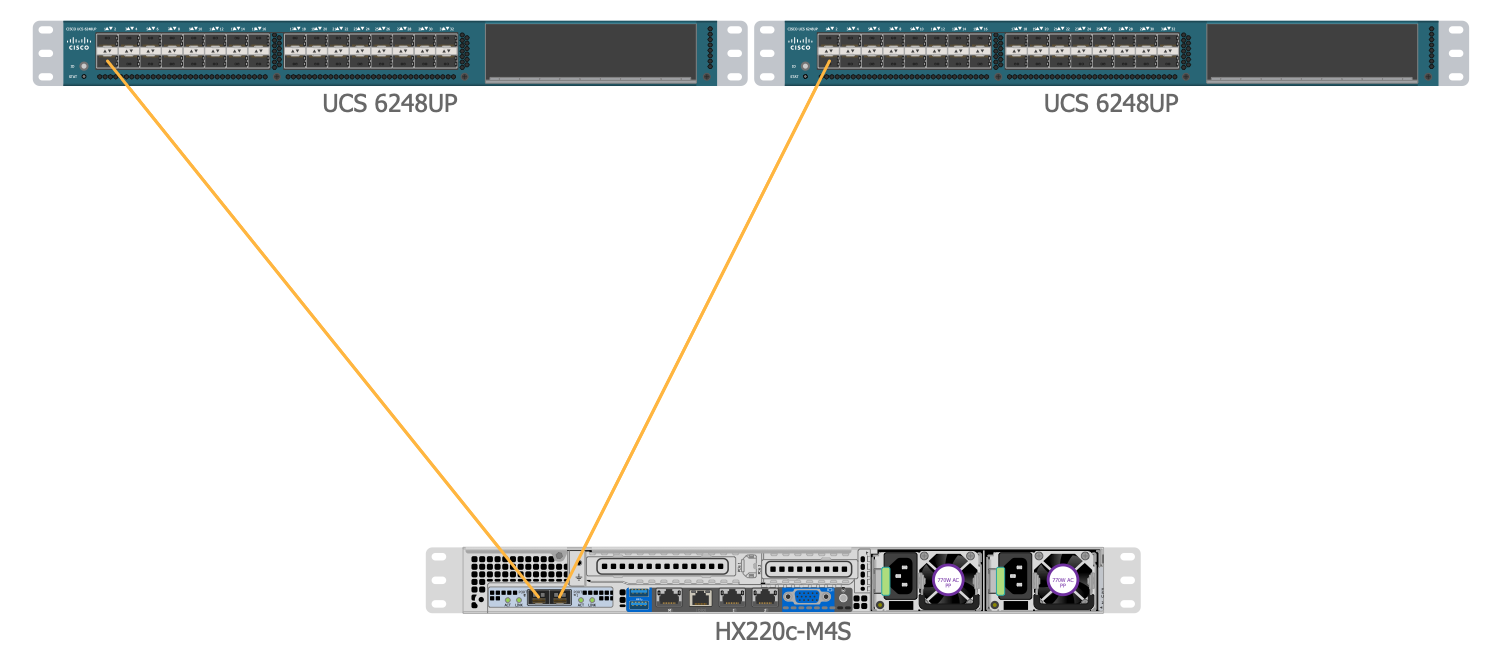
This connectivity diagram sample depicts the HX Series Server Connectivity. Being constructed on the base of the "HX-Series Server Connectivity" schematic from the article "Cisco HyperFlex Hyperconverged System with 1000 XenDesktop 7 Seats", this diagram is strict, clear, and scalable due to the used pre-made vector objects from the ConceptDraw’s Cisco Networking solution. There are depicted two UCS 6248UP switches connected with the HX220c-M4S server. The similar servers of the HX-Series are typically connected directly to the Cisco UCS Fabric Interconnects. This option is convenient for managing the HX-Series rack-mount servers using a single cable for both data traffic and management traffic. Use the ConceptDraw DIAGRAM software to model physical topologies, to design the systems' configurations, and to depict architectures with the use of internationally recognized Cisco network devices and equipment in minutes and without efforts. Place the elements sequentially and maintain the distances between them to keep the clarity of the image.
Example 7: UCS Cluster
This diagram was created in ConceptDraw DIAGRAM using the composition of libraries from the Cisco Networking Solution. An experienced user spent 5 minutes creating this sample.
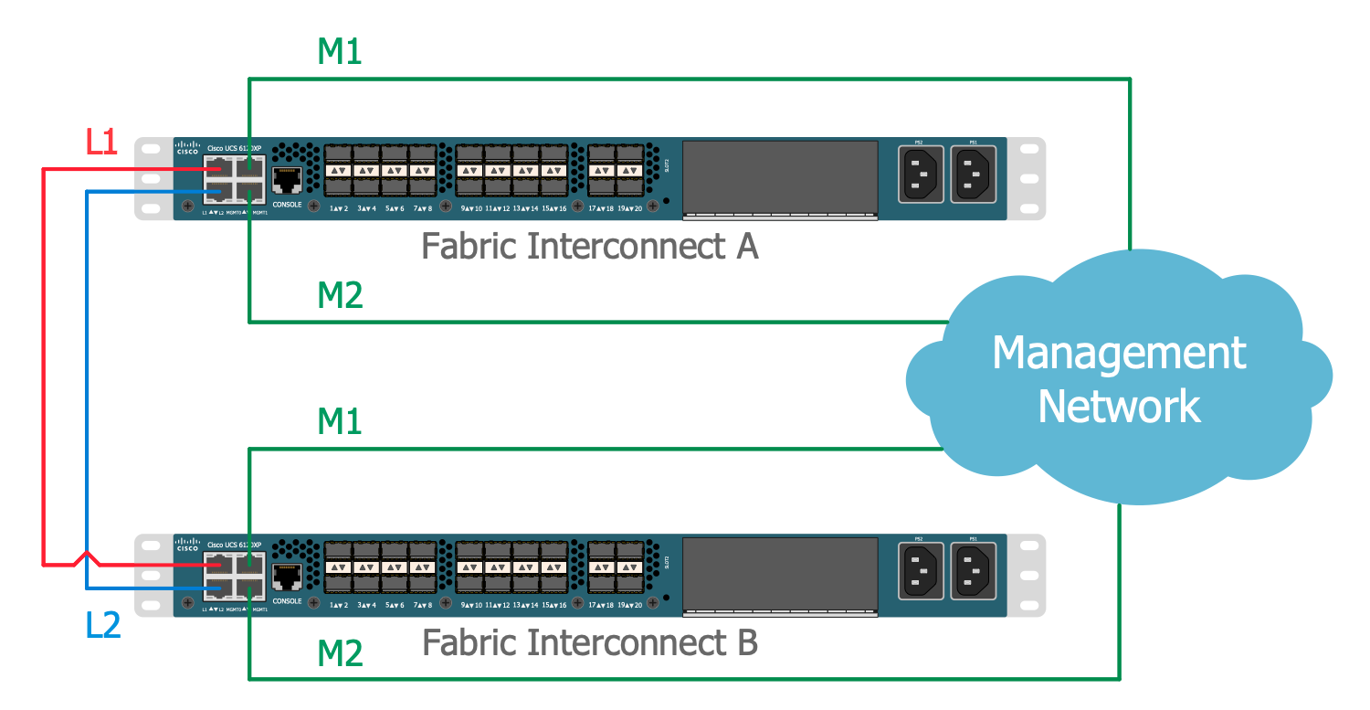
This connectivity diagram sample illustrates the structure of the UCS Cluster. The scheme is based on the "UCS Cluster" illustration made for the "Cisco Virtualized Multi-Tenant Data Center, Version 1.1, Design and Deployment Guide". The Cisco UCS (Unified Computing System) is a range of rack-mount and blade servers. There are two Fabric Interconnects (FIs) on the diagram, which are joined into a cluster. These Cisco Fabric Interconnects are connected with Ethernet cables between the L1 and L2 ports, on the diagram they are differentiated by colors — red and blue. These interconnections provide well-coordinated work of the Fabric Interconnects, if one of them will become unavailable, another one will receive an alert of failure and will take management automatically. So, the Fabric Interconnects continuously monitor the statuses of each other. ConceptDraw DIAGRAM software and the Cisco Networking solution's range of vector design elements are the best help in designing similar diagrams.
Example 8: Proper Connection Between the Server Chassis and two Fabric Interconnects
This diagram was created in ConceptDraw DIAGRAM using the composition of libraries from the Cisco Networking Solution. An experienced user spent 10 minutes creating this sample.
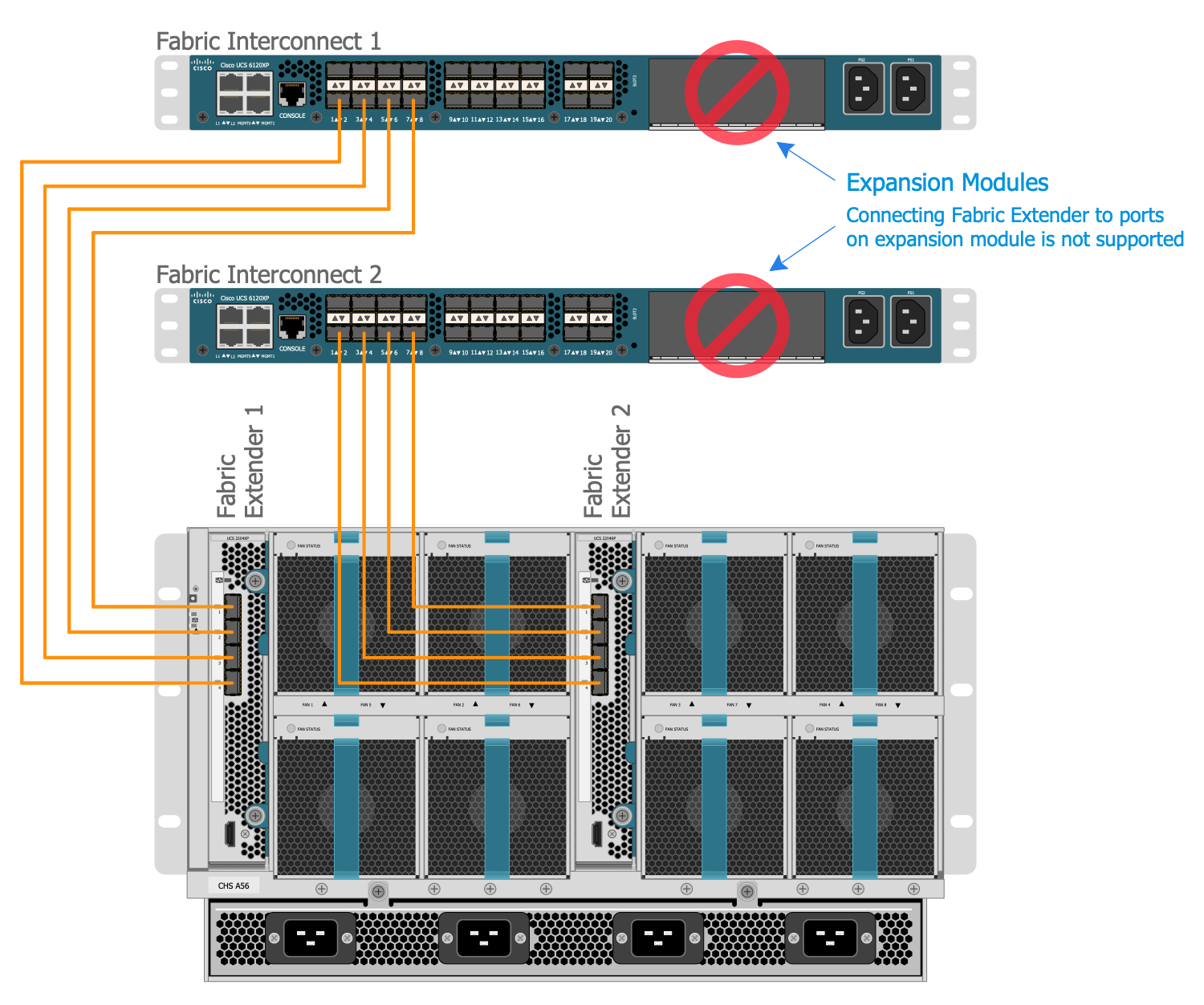
This diagram depicts the proper connection between the Server Chassis and two Fabric Interconnects, which was designed on the base of the "Proper Connection Between the Server Chassis and two UCS6100 Series Fabric Interconnects" illustration published at the article "Cisco Virtualized Multi-Tenant Data Center, Version 1.1, Design and Deployment Guide". Two Fabric Extenders placed at the back of the Blade Server Chassis provide four 10 GE ports each one and are connected to the corresponding separate Fabric Interconnects with ensuring the redundancy and bandwidth aggregation. There are highlighted the expansion modules, connecting Fabric Extender to ports on the expansion module is not supported. The abundance of ConceptDraw tools and vector design elements lets construct the complex accurate diagrams, supply them with the textual descriptions, bright arrows and signs with exhaustive comments, you can add an explaining legend, and other elements you need to make your diagrams the most comprehensible.
Example 9: HyperFlex Hyperconverged Plus Compute Only Node Topology
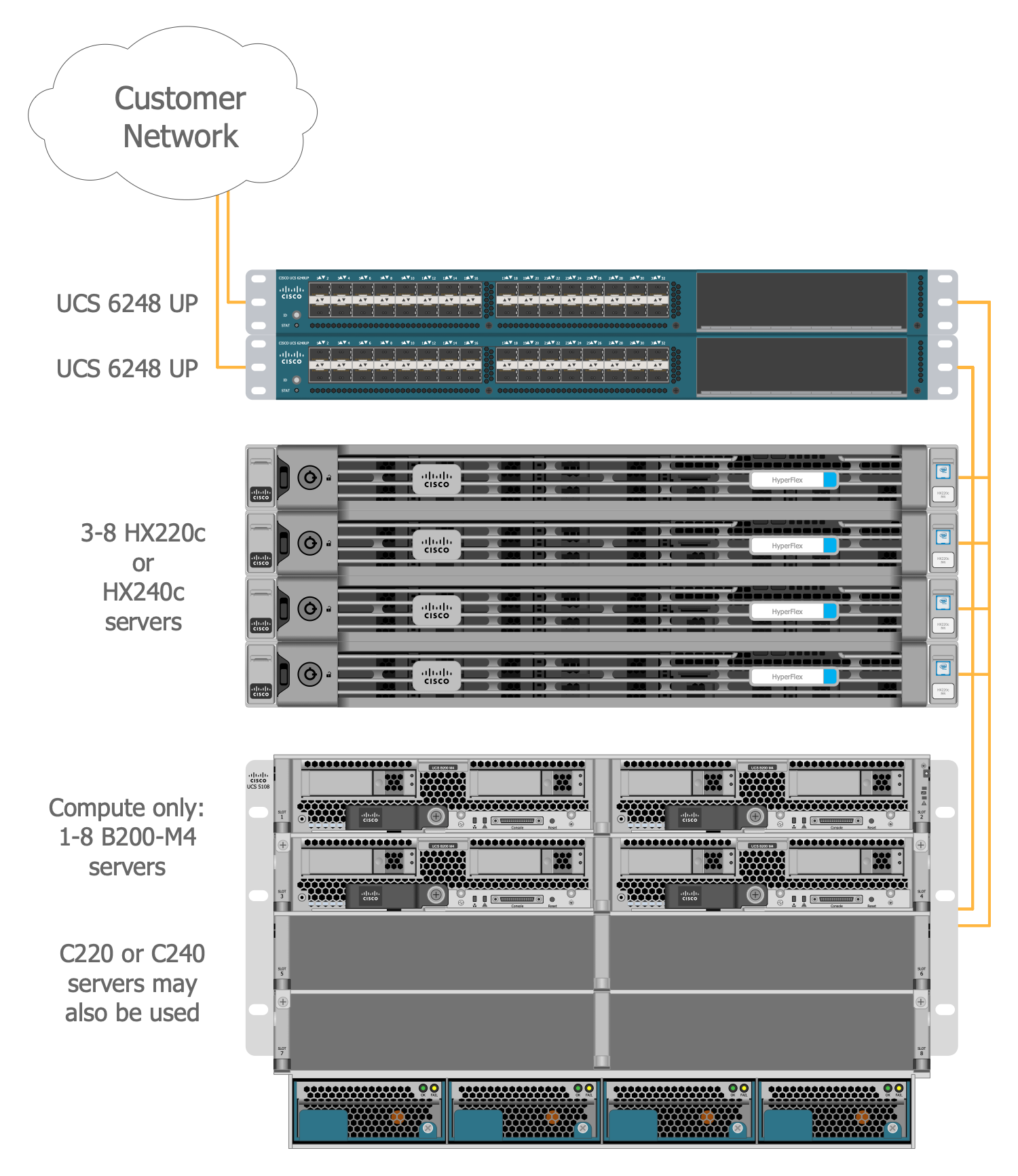
This diagram was created in ConceptDraw DIAGRAM using the composition of libraries from the Cisco Networking Solution. An experienced user spent 10 minutes creating this sample.
This physical topology diagram is a sample of the HyperFlex Hyperconverged Plus Compute Only Node Topology. It was drawn on the base of the same-named illustration from the article "Cisco HyperFlex Hyperconverged System with 1000 XenDesktop 7 Seats". You can see that the Cisco HyperFlex system includes several components: a pair of Cisco UCS 6248UP Fabric Interconnects, from 3 up to 8 HX-Series rack-mount servers per cluster, these can be HX220c or HX240c servers. The minimal quantity of servers that can be added per cluster is 3 and 8 is their allowable maximum. There are also used from 3 to 8 Cisco UCS B200-M4 blade servers. Cisco UCS C240 and C220 servers can be additionally used for extension the compute resources. ConceptDraw DIAGRAM enhanced with Cisco Networking solution tools is perfect diagramming software to represent different configurations and architectures using the Cisco equipment represented by the ready-made ConceptDraw vector design elements.
Example 10: HyperFlex Hyperconverged Cluster Topology
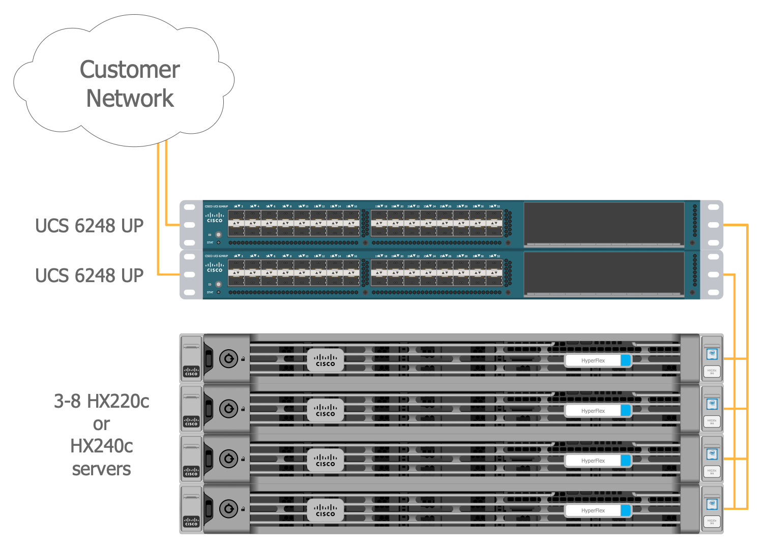
This diagram was created in ConceptDraw DIAGRAM using the composition of libraries from the Cisco Networking Solution. An experienced user spent 5 minutes creating this sample.
This physical topology diagram sample represents the HyperFlex Hyperconverged Cluster Topology. It was drawn by means of ConceptDraw tools on the base of the "HyperFlex Hyperconverged Cluster Topology" image published at the "Cisco HyperFlex Hyperconverged System with 1000 XenDesktop 7 Seats" article. The Cisco HyperFlex is the newest hyper-converged system that allows solving the problems of high complexity of the fault-tolerant data center systems and corporate infrastructures. It integrates the computing infrastructure, virtual machines, and storage into a single fault-tolerant and high-performance infrastructure. The Cisco HyperFlex system structure depicted on this sample includes a pair of Cisco UCS 6248UP Fabric Interconnects and from 3 to 8 HX-Series rack mount servers (HX220c or HX240c). It is a perfect switching solution, universal and supporting any IP / FC / FCoE / iSCS protocol, the Cisco UCS Manager control system is installed on it. The Cisco UCS 5108 Blade chassis can be added for providing additional compute resources in hybrid clusters.
Inside
What I Need to Get Started
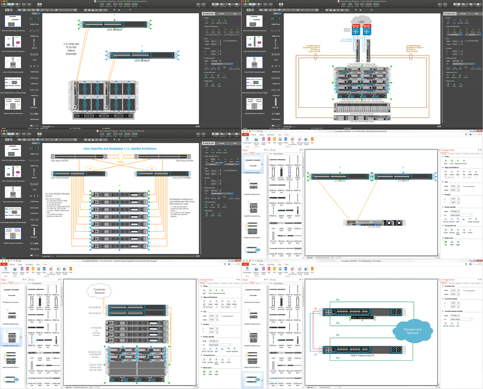
Both ConceptDraw DIAGRAM diagramming and drawing software and the Cisco Networking solution can help creating the cisco network diagrams you need. The Cisco Networking solution can be found in the Computer and Networks area of ConceptDraw STORE application that can be downloaded from this site. Make sure that both ConceptDraw DIAGRAM and ConceptDraw STORE applications are installed on your computer before you get started.
How to install
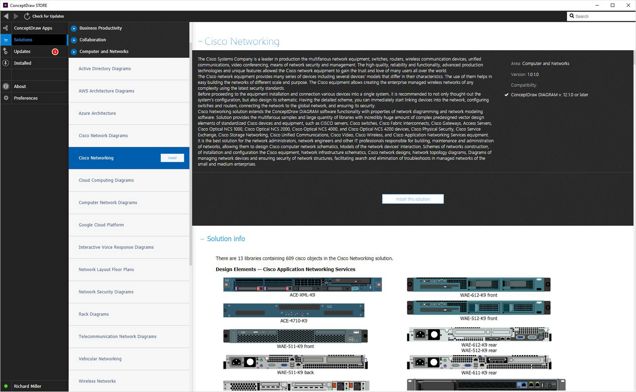
After ConceptDraw STORE and ConceptDraw DIAGRAM are downloaded and installed, you can install the Cisco Network Diagraming from the ConceptDraw STORE.
Start using
To make sure that you are doing it all right, use the pre-designed symbols from the stencil libraries from the solution to make your drawings look smart and professional. Also, the pre-made examples from this solution can be used as drafts so your own drawings can be based on them. Using the samples, you can always change their structures, colors and data.
