- Electric and Telecom Plans Free
- Fire and Emergency Plans Free
- Floor Plans Free
- Plant Layout Plans Free
- School and Training Plans Free
- Seating Plans Free
- Security and Access Plans Free
- Site Plans Free
- Sport Field Plans Free
- Business Process Diagrams Free
- Business Process Mapping Free
- Classic Business Process Modeling Free
- Cross-Functional Flowcharts Free
- Event-driven Process Chain Diagrams Free
- IDEF Business Process Diagrams Free
- Logistics Flow Charts Free
- Workflow Diagrams Free
- ConceptDraw Dashboard for Facebook Free
- Mind Map Exchange Free
- MindTweet Free
- Note Exchange Free
- Project Exchange Free
- Social Media Response Free
- Active Directory Diagrams Free
- AWS Architecture Diagrams Free
- Azure Architecture Free
- Cisco Network Diagrams Free
- Cisco Networking Free
- Cloud Computing Diagrams Free
- Computer Network Diagrams Free
- Google Cloud Platform Free
- Interactive Voice Response Diagrams Free
- Network Layout Floor Plans Free
- Network Security Diagrams Free
- Rack Diagrams Free
- Telecommunication Network Diagrams Free
- Vehicular Networking Free
- Wireless Networks Free
- Comparison Dashboard Free
- Composition Dashboard Free
- Correlation Dashboard Free
- Frequency Distribution Dashboard Free
- Meter Dashboard Free
- Spatial Dashboard Free
- Status Dashboard Free
- Time Series Dashboard Free
- Basic Circle-Spoke Diagrams Free
- Basic Circular Arrows Diagrams Free
- Basic Venn Diagrams Free
- Block Diagrams Free
- Concept Maps Free
- Family Tree Free
- Flowcharts Free
- Basic Area Charts Free
- Basic Bar Graphs Free
- Basic Divided Bar Diagrams Free
- Basic Histograms Free
- Basic Line Graphs Free
- Basic Picture Graphs Free
- Basic Pie Charts Free
- Basic Scatter Diagrams Free
- Aerospace and Transport Free
- Artwork Free
- Audio, Video, Media Free
- Business and Finance Free
- Computers and Communications Free
- Holiday Free
- Manufacturing and Maintenance Free
- Nature Free
- People Free
- Presentation Clipart Free
- Safety and Security Free
- Analog Electronics Free
- Audio and Video Connectors Free
- Basic Circuit Diagrams Free
- Chemical and Process Engineering Free
- Digital Electronics Free
- Electrical Engineering Free
- Electron Tube Circuits Free
- Electronic Block Diagrams Free
- Fault Tree Analysis Diagrams Free
- GHS Hazard Pictograms Free
- Home Automation and Wiring Free
- Mechanical Engineering Free
- One-line Diagrams Free
- Power Сircuits Free
- Specification and Description Language (SDL) Free
- Telecom and AV Circuits Free
- Transport Hazard Pictograms Free
- Data-driven Infographics Free
- Pictorial Infographics Free
- Spatial Infographics Free
- Typography Infographics Free
- Calendars Free
- Decision Making Free
- Enterprise Architecture Diagrams Free
- Fishbone Diagrams Free
- Organizational Charts Free
- Plan-Do-Check-Act (PDCA) Free
- Seven Management and Planning Tools Free
- SWOT and TOWS Matrix Diagrams Free
- Timeline Diagrams Free
- Australia Map Free
- Continent Maps Free
- Directional Maps Free
- Germany Map Free
- Metro Map Free
- UK Map Free
- USA Maps Free
- Customer Journey Mapping Free
- Marketing Diagrams Free
- Matrices Free
- Pyramid Diagrams Free
- Sales Dashboard Free
- Sales Flowcharts Free
- Target and Circular Diagrams Free
- Cash Flow Reports Free
- Current Activities Reports Free
- Custom Excel Report Free
- Knowledge Reports Free
- MINDMAP Reports Free
- Overview Reports Free
- PM Agile Free
- PM Dashboards Free
- PM Docs Free
- PM Easy Free
- PM Meetings Free
- PM Planning Free
- PM Presentations Free
- PM Response Free
- Resource Usage Reports Free
- Visual Reports Free
- House of Quality Free
- Quality Mind Map Free
- Total Quality Management TQM Diagrams Free
- Value Stream Mapping Free
- Astronomy Free
- Biology Free
- Chemistry Free
- Language Learning Free
- Mathematics Free
- Physics Free
- Piano Sheet Music Free
- Android User Interface Free
- Class Hierarchy Tree Free
- Data Flow Diagrams (DFD) Free
- DOM Tree Free
- Entity-Relationship Diagram (ERD) Free
- EXPRESS-G data Modeling Diagram Free
- IDEF0 Diagrams Free
- iPhone User Interface Free
- Jackson Structured Programming (JSP) Diagrams Free
- macOS User Interface Free
- Object-Role Modeling (ORM) Diagrams Free
- Rapid UML Free
- SYSML Free
- Website Wireframe Free
- Windows 10 User Interface Free
Cisco Network Diagrams
Cisco is an American multinational company, one of the largest in the world dealing in a field of high technologies, development and selling the network equipment, mainly intended for the large organizations and telecommunication companies, which is also specialized in certification of computer network engineers. Cisco maintains the leadership in different segments, such as routing, switching, IP communications, unified communications, wireless networking, network security, video systems and applied networking services. The Cisco services, solutions, equipment, and resources are widely used for designing and deployment the computer networks, allowing the individuals, companies, and even the whole cities, regions and countries to improve the quality of services, to increase the productivity and competitiveness. Cisco provides a huge range of hardware for construction of the information networks and ensuring the access to them, as well as the Cisco IOS operating system, which provides support for the network services and applications, technical support, maintenance services and optimization of network operation. Cisco uses the set of its own brand networking symbols, which are globally recognized, easy identifiable and generally accepted as standard. The Cisco icons and Cisco network symbols are used for construction different Cisco Network Diagrams, Cisco networks designs and Network topology diagrams visualizing computer network topologies, Cisco network equipment arrangement and connections.
Cisco Network Diagrams solution extends ConceptDraw DIAGRAM with the best characteristics of network diagramming software. It includes numerous samples, templates and libraries of built-in standardized vector Cisco network icons and Cisco symbols of computers, network devices, network appliances and other Cisco network equipment to help network engineers, network designers, network and system administrators, and other IT professionals and corporate IT departments to diagram efficiently the network infrastructure, to visualize computer networks topologies, to design Cisco computer networks, and to create professional-looking Cisco Computer network diagrams, Cisco network designs and schematics, Network maps, and Network topology diagrams in minutes.
-
Install this solution Free -
What I need to get started -
Solution Requirements - This solution requires the following products to be installed:
ConceptDraw DIAGRAM v18 - This solution requires the following products to be installed:
-
Compatibility - Sonoma (14), Sonoma (15)
MS Windows 10, 11 - Sonoma (14), Sonoma (15)
-
Support for this Solution -
Helpdesk
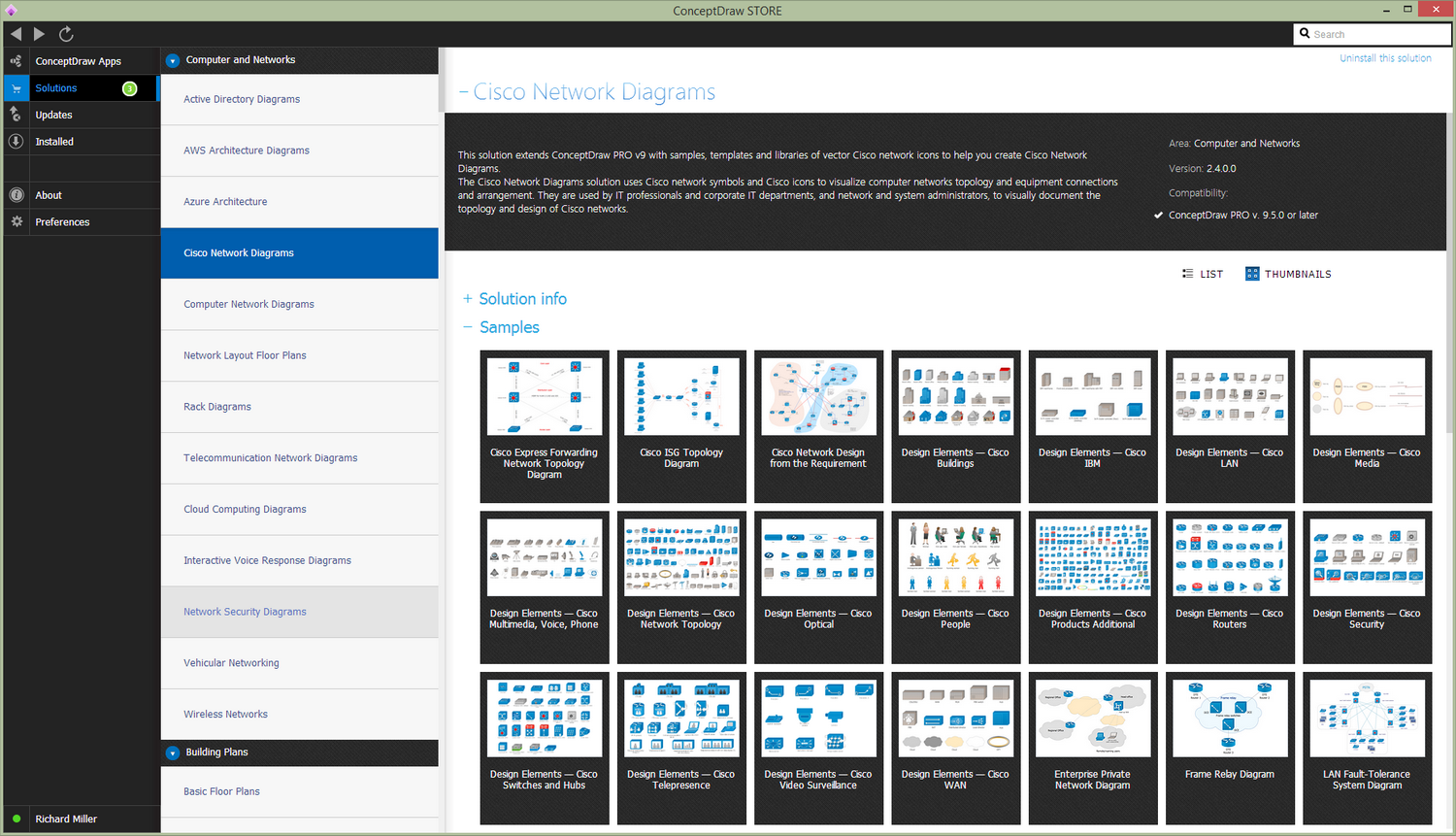
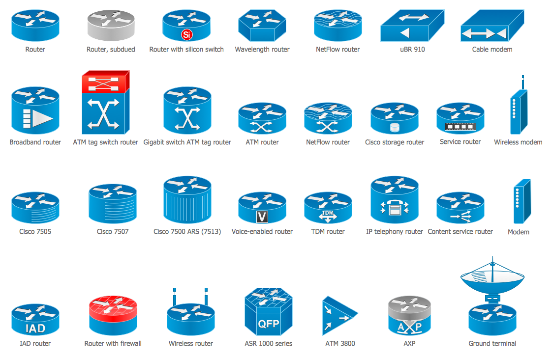
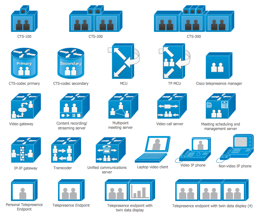
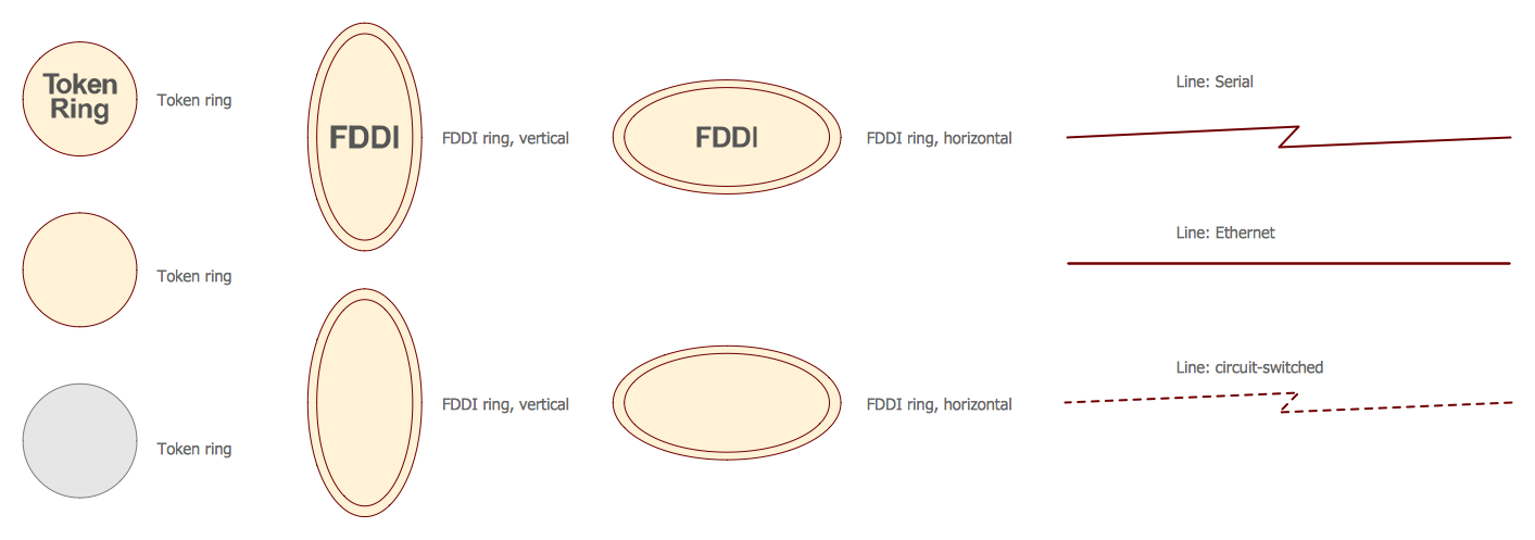
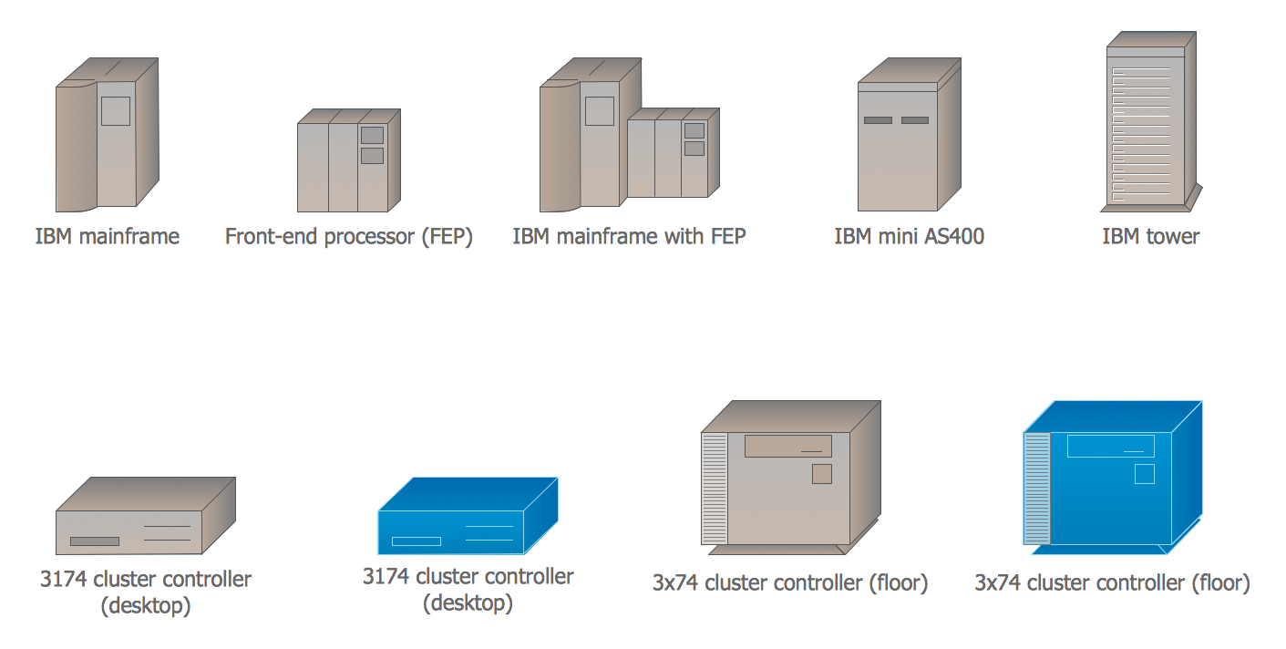
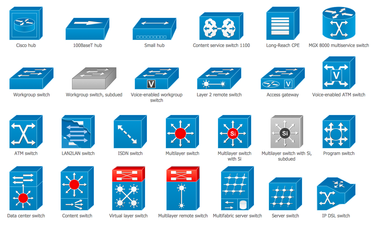
There are 15 libraries containing 508 cisco objects in the Cisco Network Diagrams solution.
Design Elements — Cisco Switches & Hubs
Examples
There are a few samples that you see on this page which were created in the ConceptDraw DIAGRAM application by using the Cisco Network Diagrams solution. Some of the solution's capabilities as well as the professional results which you can achieve are all demonstrated here on this page.
All source documents are vector graphic documents which are always available for modifying, reviewing and/or converting to many different formats, such as MS PowerPoint, PDF file, MS Visio, and many other graphic ones from the ConceptDraw Solution Park or ConceptDraw STORE. The Cisco Network Diagrams solution is available to all ConceptDraw DIAGRAM users to get installed and used while working in the ConceptDraw DIAGRAM diagramming and drawing software.
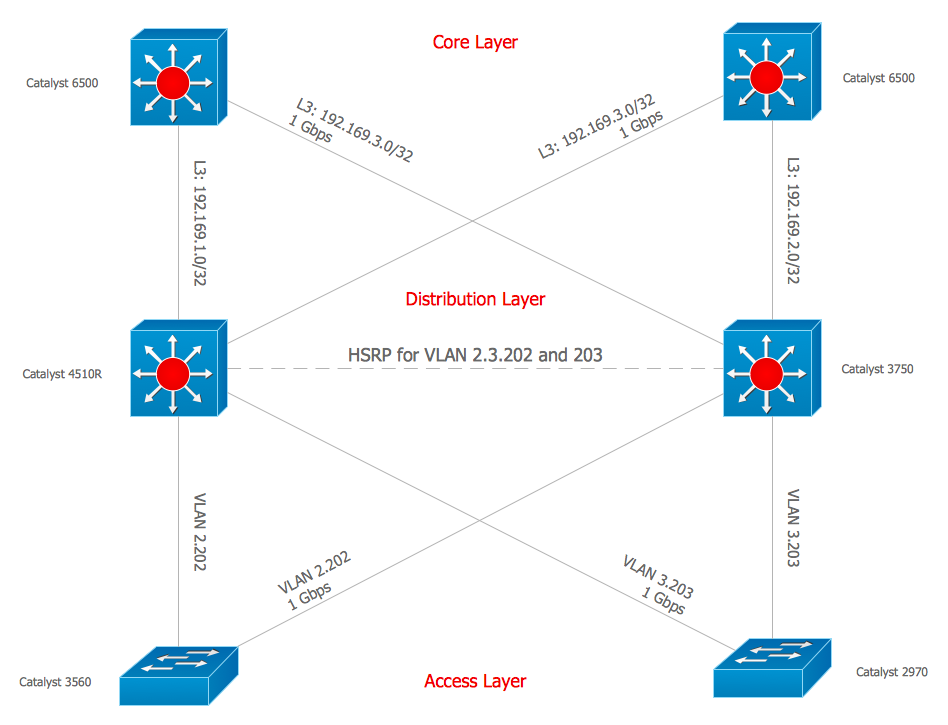
Example 1: Cisco Express Forwarding Network Topology Diagram
This example was created in ConceptDraw DIAGRAM using the Cisco Network Topology and Cisco Switches and Hubs libraries from the Cisco Network Diagrams solution. An experienced user spent 20 minutes creating this sample.
This example diagram depicts a network topology built using the Cisco Express Forwarding (CEF) technology. It is a high-speed routing and switching packets technology, used by default at the third-level routers and switches produced by the Cisco Systems Incorporation. This technology allows to achieve more rapid and efficient handling of transit traffic, provides ability of operative switching packets through devices, at the same time keeping low the load on the router’s processor, while the router processor can be assigned to perform other responsibilities that require greater amounts of processor's time, such as encryption, quality of service, and others. The CEF switching technology is used mainly at the large core networks or over the Internet to enhance the overall network performance. Currently it supports the protocols of Ethernet, Frame Relay, ATM, PPP, FDDI, HDLC and others. The CEF is a three-layered technology, all three layers you can see depicted on this diagram: core layer, distribution layer, and access layer.
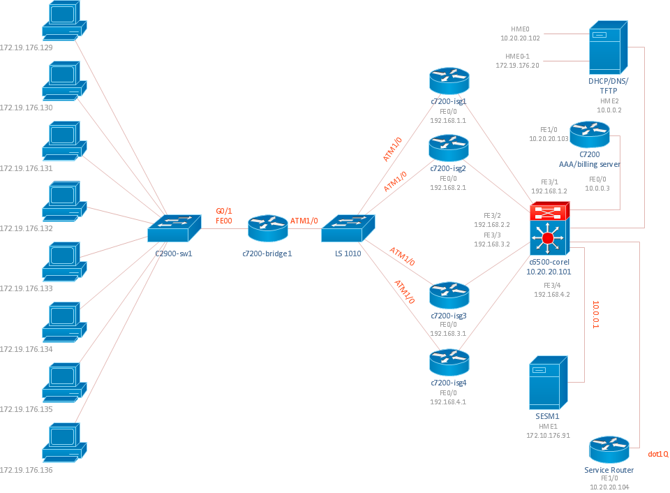
Example 2: Cisco ISG Topology Diagram
This example was created in ConceptDraw DIAGRAM using libraries from the Cisco Network Diagrams solution. The libraries used were Cisco LAN, Cisco Switches and Hubs, Cisco Routers, Cisco Products Additional, and Cisco Network Topology. An experienced user spent 30 minutes creating this sample.
The Cisco Intelligent Service Gateway (ISG) is a technology provided by the Cisco Systems for management by subscribers in a broadband, wireless and wireline deployments. The ISG supplies the service providers with opportunity to take under the full control resources and characteristics in their broadband network with a goal to deliver next generation services. The Cisco ISG available at the Cisco routers automatically registers the attempts of subscribers to access to the network and identifies the type of service that is required for each subscriber, as well as the type of used device. The Cisco ISG is able to control the access to the services of different types, like as multimedia subsystems and other services, including those that not use the Session Initiation Protocol (SIP). The network topology depicted at this sample was built using the Cisco Intelligent Services Gateway (ISG). Using the predesigned Cisco icons from the libraries listed above you can produce complex Cisco Network Diagrams that adhere to the accepted standards of Cisco drawings.
Example 3: LAN Fault-Tolerance System Diagram
This example was created in ConceptDraw DIAGRAM using libraries from the Cisco Network Diagrams solution. The libraries used were Cisco WAN, Cisco Switches and Hubs, and Cisco Routers. An experienced user spent 20 minutes creating this sample.
Directions associated with prevention of faults and with fault-tolerance are key for ensuring the reliability of computing systems. The fault-tolerance is a property of computer system to save performance and to continue the actions defined by the program in a case of occurrence any faults, errors, damages, failures of individual devices, units or circuits. Any fault-tolerant system characterizes by redundancy. The high performance and reliability, the capability for automatic reconfiguration and continued operation even after occurrence the faults is achieved in parallel computing systems, multiprocessor and multimachine systems. The most fault-tolerant computer systems are able to process several possible failures, including the failures of hardware, hard disks, input and output devices, software bugs, interface errors, bad command sequences, physical damages, and others. This sample shows a diagram depicting LAN fault-tolerance system. Using the ConceptDraw libraries, you can access a wide array of Cisco network icons, so you can quickly prototype a new network or document an existing one.
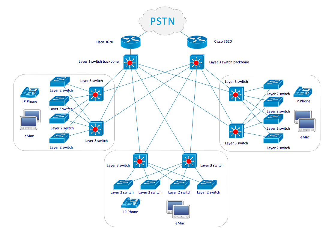
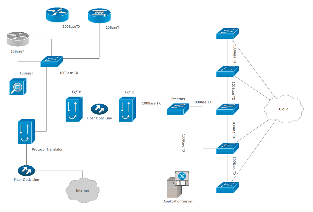
Example 4: Network Organization Chart
This example was created in ConceptDraw DIAGRAM using libraries from the Cisco Network Diagrams solution. The libraries used were Cisco Optical, Cisco Switches and Hubs, Cisco Routers, Cisco Products Additional, and Cisco Network Topology. An experienced user spent 10 minutes creating this sample.
The correctly organized network influences on many processes in organization and is the base of the accurate organization's work. The Network Organization Chart is a graphical representation of the hierarchical network organizational structure. It depicts the network functional units, used network devices and appliances, as well as visually illustrates dependencies between all nodes with help of network connections and links. The Network Organization Chart can be a great start for detailed network documentation, as well as serve as a visual instruction for new IT staff, or as a detailed illustration for a presentation of a designed network that will be constructed soon. With ConceptDraw DIAGRAM network diagramming software, you can create your own diagrams representing the networks’ organizational structures in minutes. This Network Organization Chart was designed on the base of Cisco hardware. You can correct this diagram, to skip some details or vice versa clarify some parts, to change equipment or to make other modifications depending on your needs.
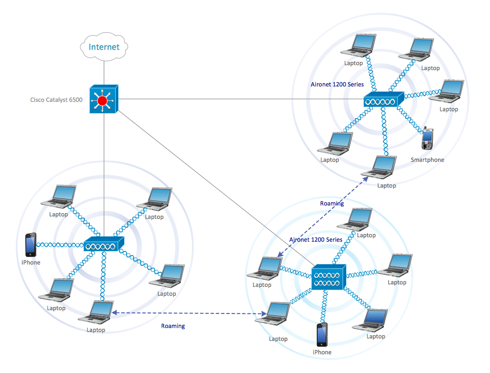
Example 5: Roaming Wireless Local Area Network Diagram
This example was created in ConceptDraw DIAGRAM using libraries from the Cisco Network Diagrams solution. The libraries used were Cisco Switches and Hubs, Cisco Products Additional, and Cisco Network Topology. An experienced user spent 15 minutes creating this sample.
This sample diagram induces to talk about the roaming. There are two types of wireless LAN roaming: internal and external. The internal roaming lets the mobile station (MS) to move within the area with multiple access points and to switch automatically from one access point (AP) to another, which has better signal strength at the moment. The external roaming lets the mobile station to move into the WLAN of another provider and to take its wireless services. This is an example of a Roaming Wireless Local Area Network Diagram designed in ConceptDraw DIAGRAM software with help of Cisco Network Diagrams solution tools, which can be used for the educational or presentation needs, or as an illustration for professionally oriented analytical article. You can modify this example diagram with just a few clicks, add any additional Cisco icons, if needed, and to generate the illustration that is well suited to your current needs.
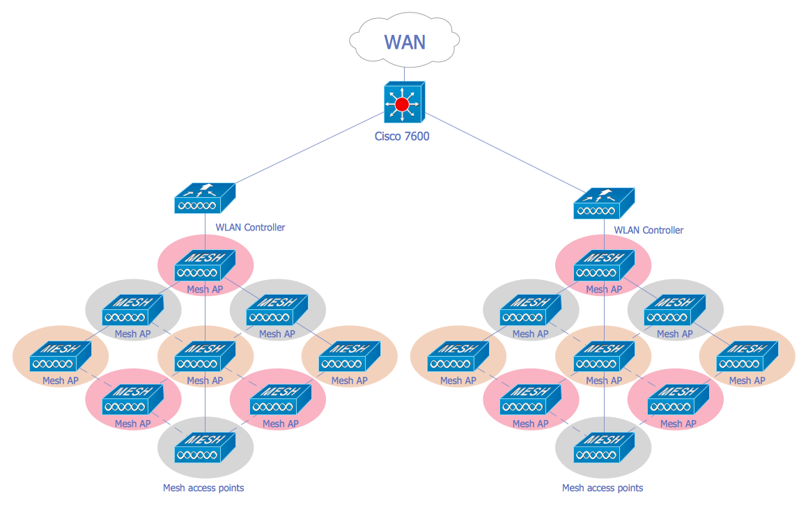
Example 6: Wireless Mesh Network Diagram
This example was created in ConceptDraw DIAGRAM using libraries from the Cisco Network Diagrams solution. The libraries used were Cisco Switches and Hubs, Cisco Products Additional, and Cisco Network Topology. An experienced user spent 10 minutes creating this sample.
A Wireless Mesh Network (WMN) is a type of communications network constructed with the radio nodes organized in a mesh topology using different wireless technologies. A WMN technology greatly extends opportunities and functionality of wireless access to the Internet, provides rich interconnections among devices and nodes. A Wireless Mesh Network consists from the gateways, the mesh routers forward the traffic to and from gateways, and the mesh clients, the typical ones are mobile phones, laptops and other wireless devices. Among numerous WMN advantages is its reliably and redundancy, it can be quickly deployed and provides secure wireless coverage (called a mesh cloud) as inside the premises as outside them, and of course we need to mention its ability for self-forming and self-healing, the nodes can communicate with each other directly or via the intermediate nodes, when some node can't operate anymore. This example is a schematic diagram of WMN that can be used to illustrate network documentation or educational materials about wireless networks.
Example 7: Cisco Network Diagram — Enterprise Private Network
This example was created in ConceptDraw DIAGRAM using libraries from the Cisco Network Diagrams solution. The libraries used were Cisco Switches and Hubs, Cisco Products Additional, and Cisco Network Topology. An experienced user spent 10 minutes creating this sample.
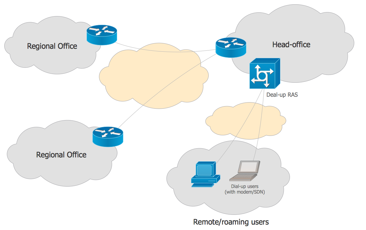
This Cisco network diagram sample is directed on depiction the Enterprise private network (EPN) using the frame-relay and dial-up. An enterprise private network is a computer network, which helps the enterprise business companies with several disparate offices to interconnect those offices in a network over a secure way and to share the computer resources. The enterprise private networks have a lot of advantages, such as encryption of messages that ensures protection of data traffic from the eavesdropping, security and privacy of data, it is also the cost efficiency and scalability of this type of networks, significant help in centralization IT resources, and the capability to provide the business continuity. As for the dial-up Internet access, it is a form of Internet access, which uses the means and facilities of Public Switched Telephone Network to set the dialed connection to Internet Service Provider, and is often used where the broadband internet access isn't available.
Example 8: Cisco Network Diagram — Frame Relay
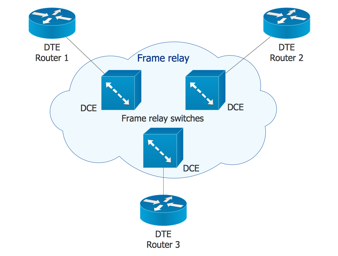
This example was created in ConceptDraw DIAGRAM using libraries from the Cisco Network Diagrams solution. The libraries used were Cisco Switches and Hubs, Cisco Products Additional, and Cisco Network Topology. An experienced user spent 10 minutes creating this sample.
The frame relay is a standardized WAN (Wide Area Network) technology, which defines the physical and logical link layers of the digital telecommunications channels using the methodology of switching packets. The frame relay uses the newest achievements in technology of data transferring in global networks, it provides ability to transmit the data with commutation of packets through the interface between user devices (routers, bridges, computers, etc.) and network equipment (for example, switching nodes), and ensures high productivity and efficiency without compromising the information integrity. The users' devices are named the data terminal equipment (DTE), while the network equipment that provides the agreement with DTE is named the data circuit-terminating equipment (DCE). The network providing the frame relay interface can be either public data network or a network with equipment privately owned and supporting some separate enterprise. This example demonstrates the basic Cisco network diagram of a frame relay network.
Example 9: Logical Network Connections Diagram
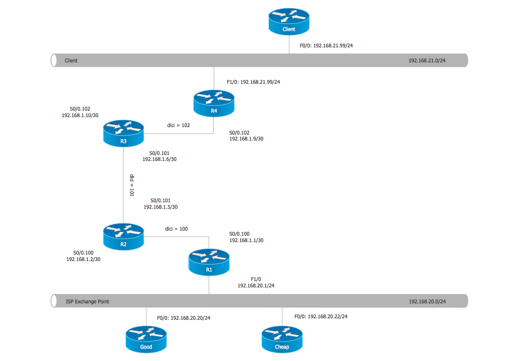
This example was created in ConceptDraw DIAGRAM using libraries from the Cisco Network Diagrams solution. The libraries used were Cisco Switches and Hubs, Cisco Products Additional, and Cisco Network Topology. An experienced user spent 10 minutes creating this sample.
The logical topology (signal topology) is the placement of different devices at the computer network and their communications with one another. As for the network physical structure, physical layout of computer network devices and their physical connections with cables for the data transmission, it is named the network physical topology. The network logical topology is bound to the network protocols, it determines including the mechanism of communication the systems across physical topologies and how the data move through the network. The network physical and logical topologies can differ, and respectively their graphical representations for the same network at this case will vary. This Cisco Network Diagram illustrates the logical connections at the computer network constructed with Cisco network equipment. The powerful tools of Cisco Network Diagrams solution and the intuitive interface of ConceptDraw DIAGRAM software are the tangible help in rapid drawing the accurate and attractive Cisco network diagrams of any degree of complexity.
Example 10: Logical Network Diagram
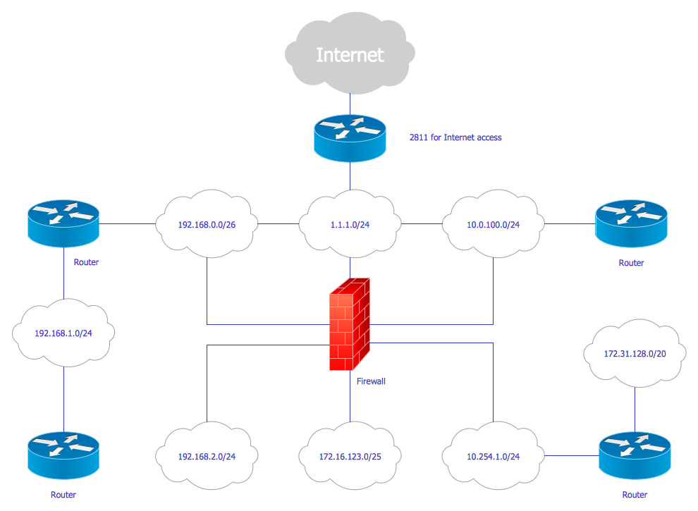
This example was created in ConceptDraw DIAGRAM using libraries from the Cisco Network Diagrams solution. The libraries used were Cisco Switches and Hubs, Cisco Products Additional, and Cisco Network Topology. An experienced user spent 10 minutes creating this sample.
This Cisco logical computer network diagram example was created in ConceptDraw DIAGRAM diagramming and vector drawing software using the tools and vector object libraries of Cisco Network Diagrams solution. If the physical topology is the geometry of the network's construction, the logical topology determines direction of data flows between the network nodes and data transmission methods. Nowadays the Cisco network equipment is widely used in construction the computer networks. The Cisco icons of network devices, computers, routers, switches, hubs, firewalls, servers, security devices, video surveillance devices, telepresence devices, clouds and much more Cisco network symbols from the solution's libraries are useful for designing computer network topologies, for organizing the network information and representing it in a graphical view. They are helpful in creation the accurate and comprehensive diagrams, designs, schematics, and maps for the networks constructed on the base of Cisco equipment, which the best suit for further using in documentation and presentations.
More Examples and Templates
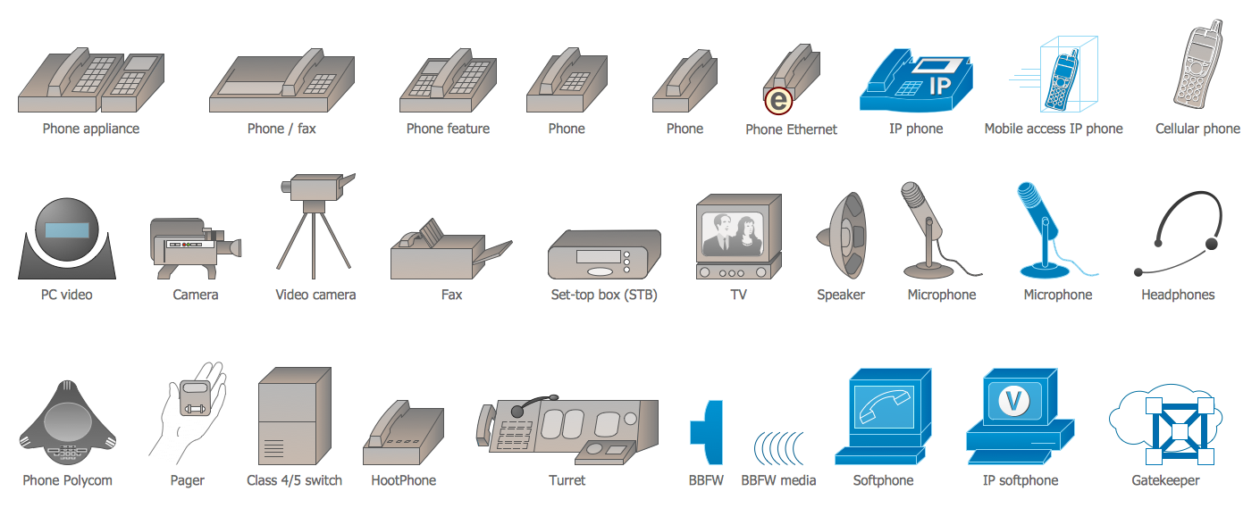
Design Elements — Cisco Multimedia, Voice, Phone
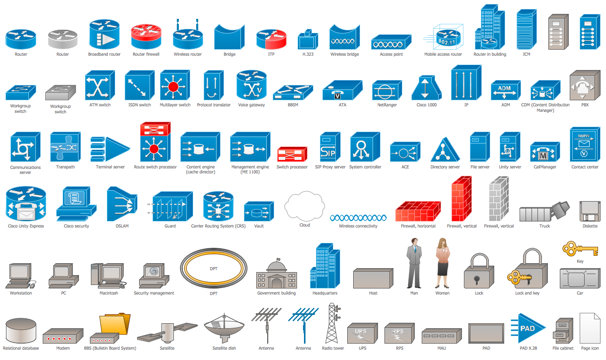
Design Elements — Cisco Network Topology

Design Elements — Cisco Optical

Design Elements — Cisco People
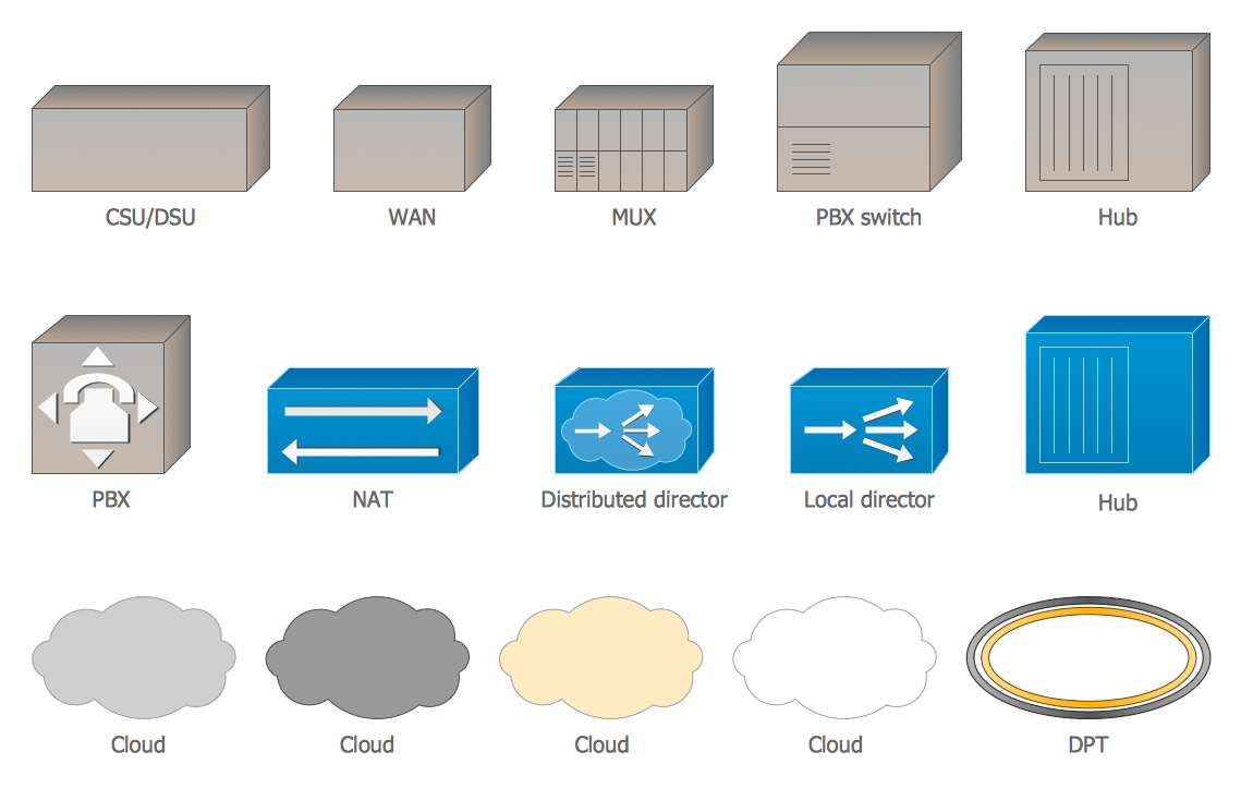
Design Elements — Cisco WAN
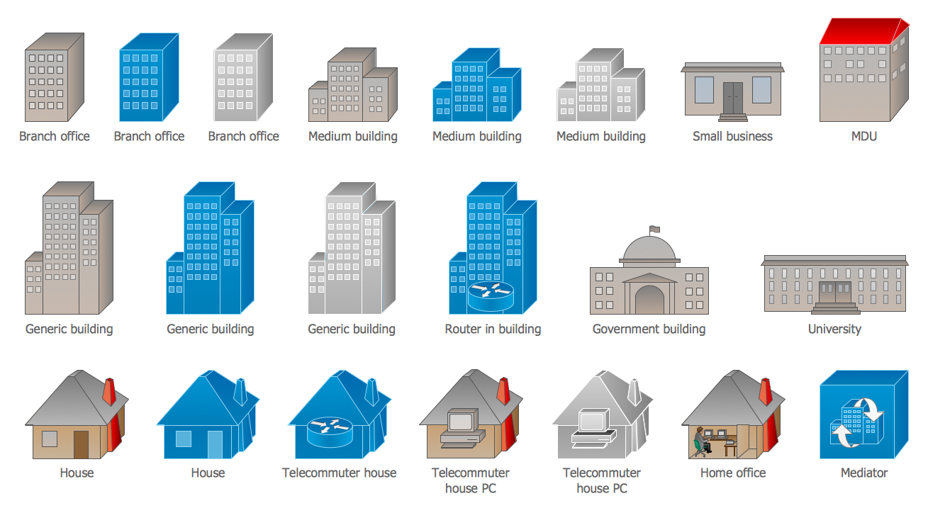
Design Elements — Cisco Buildings
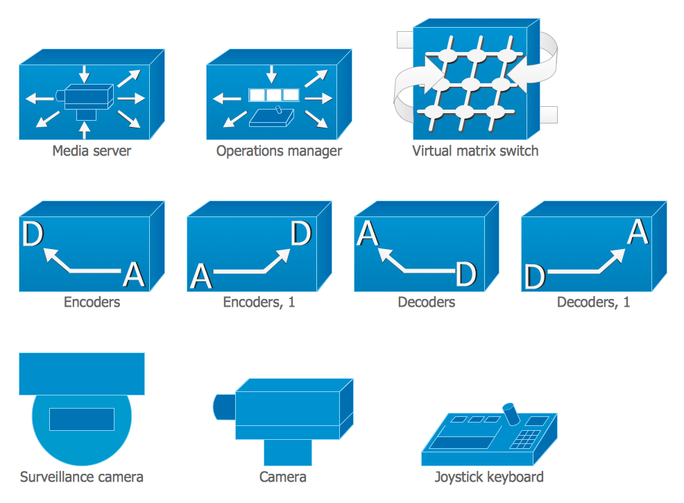
Design Elements — Cisco Video Surveillance
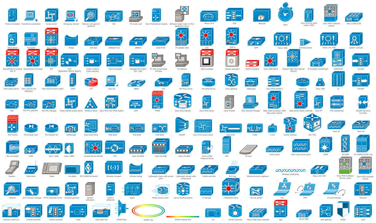
Design Elements — Cisco Products Additional
Inside
What I Need to Get Started
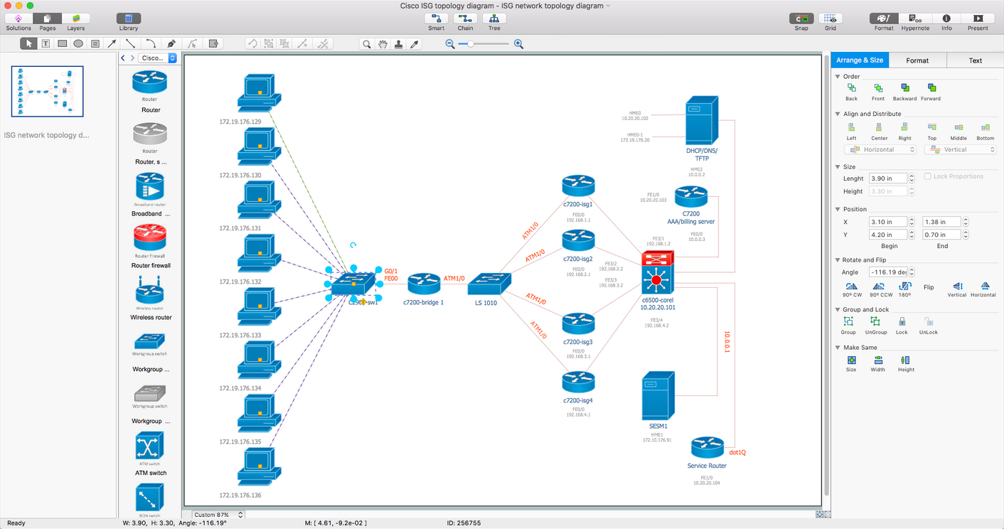
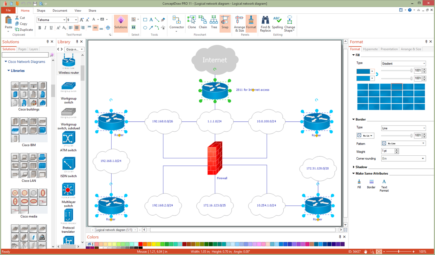
Both ConceptDraw DIAGRAM diagramming and drawing software and the Cisco Network Diagrams solution can help creating the cisco network diagrams you need. The Cisco Network Diagrams solution can be found in the Computer and Networks area of ConceptDraw STORE application that can be downloaded from this site. Make sure that both ConceptDraw DIAGRAM and ConceptDraw STORE applications are installed on your computer before you get started.
How to install
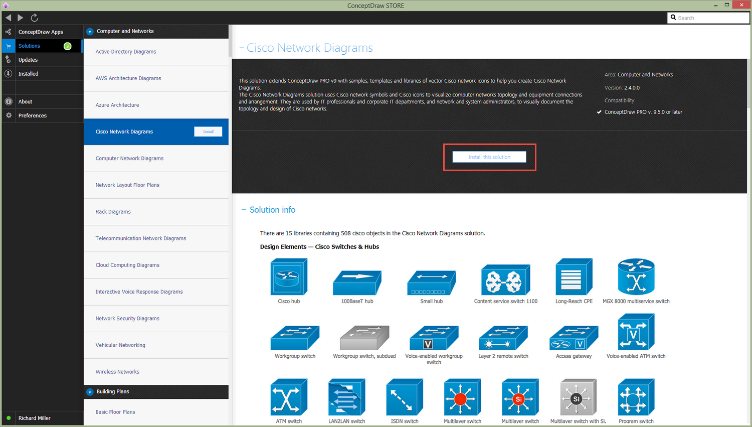
After ConceptDraw STORE and ConceptDraw DIAGRAM are downloaded and installed, you can install the Cisco Network Diagrams solution from the ConceptDraw STORE.
Start using
To make sure that you are doing it all right, use the pre-designed symbols from the stencil libraries from the solution to make your drawings look smart and professional. Also, the pre-made examples from this solution can be used as drafts so your own drawings can be based on them. Using the samples, you can always change their structures, colors and data.
