- Electric and Telecom Plans Free
- Fire and Emergency Plans Free
- Floor Plans Free
- Plant Layout Plans Free
- School and Training Plans Free
- Seating Plans Free
- Security and Access Plans Free
- Site Plans Free
- Sport Field Plans Free
- Business Process Diagrams Free
- Business Process Mapping Free
- Classic Business Process Modeling Free
- Cross-Functional Flowcharts Free
- Event-driven Process Chain Diagrams Free
- IDEF Business Process Diagrams Free
- Logistics Flow Charts Free
- Workflow Diagrams Free
- ConceptDraw Dashboard for Facebook Free
- Mind Map Exchange Free
- MindTweet Free
- Note Exchange Free
- Project Exchange Free
- Social Media Response Free
- Active Directory Diagrams Free
- AWS Architecture Diagrams Free
- Azure Architecture Free
- Cisco Network Diagrams Free
- Cisco Networking Free
- Cloud Computing Diagrams Free
- Computer Network Diagrams Free
- Google Cloud Platform Free
- Interactive Voice Response Diagrams Free
- Network Layout Floor Plans Free
- Network Security Diagrams Free
- Rack Diagrams Free
- Telecommunication Network Diagrams Free
- Vehicular Networking Free
- Wireless Networks Free
- Comparison Dashboard Free
- Composition Dashboard Free
- Correlation Dashboard Free
- Frequency Distribution Dashboard Free
- Meter Dashboard Free
- Spatial Dashboard Free
- Status Dashboard Free
- Time Series Dashboard Free
- Basic Circle-Spoke Diagrams Free
- Basic Circular Arrows Diagrams Free
- Basic Venn Diagrams Free
- Block Diagrams Free
- Concept Maps Free
- Family Tree Free
- Flowcharts Free
- Basic Area Charts Free
- Basic Bar Graphs Free
- Basic Divided Bar Diagrams Free
- Basic Histograms Free
- Basic Line Graphs Free
- Basic Picture Graphs Free
- Basic Pie Charts Free
- Basic Scatter Diagrams Free
- Aerospace and Transport Free
- Artwork Free
- Audio, Video, Media Free
- Business and Finance Free
- Computers and Communications Free
- Holiday Free
- Manufacturing and Maintenance Free
- Nature Free
- People Free
- Presentation Clipart Free
- Safety and Security Free
- Analog Electronics Free
- Audio and Video Connectors Free
- Basic Circuit Diagrams Free
- Chemical and Process Engineering Free
- Digital Electronics Free
- Electrical Engineering Free
- Electron Tube Circuits Free
- Electronic Block Diagrams Free
- Fault Tree Analysis Diagrams Free
- GHS Hazard Pictograms Free
- Home Automation and Wiring Free
- Mechanical Engineering Free
- One-line Diagrams Free
- Power Сircuits Free
- Specification and Description Language (SDL) Free
- Telecom and AV Circuits Free
- Transport Hazard Pictograms Free
- Data-driven Infographics Free
- Pictorial Infographics Free
- Spatial Infographics Free
- Typography Infographics Free
- Calendars Free
- Decision Making Free
- Enterprise Architecture Diagrams Free
- Fishbone Diagrams Free
- Organizational Charts Free
- Plan-Do-Check-Act (PDCA) Free
- Seven Management and Planning Tools Free
- SWOT and TOWS Matrix Diagrams Free
- Timeline Diagrams Free
- Australia Map Free
- Continent Maps Free
- Directional Maps Free
- Germany Map Free
- Metro Map Free
- UK Map Free
- USA Maps Free
- Customer Journey Mapping Free
- Marketing Diagrams Free
- Matrices Free
- Pyramid Diagrams Free
- Sales Dashboard Free
- Sales Flowcharts Free
- Target and Circular Diagrams Free
- Cash Flow Reports Free
- Current Activities Reports Free
- Custom Excel Report Free
- Knowledge Reports Free
- MINDMAP Reports Free
- Overview Reports Free
- PM Agile Free
- PM Dashboards Free
- PM Docs Free
- PM Easy Free
- PM Meetings Free
- PM Planning Free
- PM Presentations Free
- PM Response Free
- Resource Usage Reports Free
- Visual Reports Free
- House of Quality Free
- Quality Mind Map Free
- Total Quality Management TQM Diagrams Free
- Value Stream Mapping Free
- Astronomy Free
- Biology Free
- Chemistry Free
- Language Learning Free
- Mathematics Free
- Physics Free
- Piano Sheet Music Free
- Android User Interface Free
- Class Hierarchy Tree Free
- Data Flow Diagrams (DFD) Free
- DOM Tree Free
- Entity-Relationship Diagram (ERD) Free
- EXPRESS-G data Modeling Diagram Free
- IDEF0 Diagrams Free
- iPhone User Interface Free
- Jackson Structured Programming (JSP) Diagrams Free
- macOS User Interface Free
- Object-Role Modeling (ORM) Diagrams Free
- Rapid UML Free
- SYSML Free
- Website Wireframe Free
- Windows 10 User Interface Free
Basic Circuit Diagrams
A circuit diagram is a visual graphical display of an electrical circuit. It shows the operation of an electrical circuit, its components, and how they are interconnected. Special recognized symbols are used to identify components of electrical circuits including transistors, conductors, transformers, capacitors, etc. Ohm’s law and Kirchhoff’s voltage law are the basic laws that mathematically describe the work of electric circuits.
Circuit diagram plays a significant role in the design, construction, implementation, and maintenance, of electrical circuits and electronic equipment. It is also the main guideline when a modification of the electrical circuit is required. However, it is advisable to make changes to the plan in advance, before installing the electrical circuit.
The electric circuit commonly includes the energy sources providing constant voltage in the circuit (battery), devices converting mechanical energy into electrical power (generator), a conductor that provides a path for energy flowing in the circuit. It may also contain a switch closing/opening the flow of electricity in a circuit, a resistor to reduce current flow or divide voltage, and other special components. The devices using current and the connecting wires or transmission lines linking the electrical devices are also included in the electrical circuit. The wires are commonly depicted by lines and show the path of transmitting electric current. However, the Circuit diagram is a schematic representation and the lines between the components don't represent real distances between them.
One differs series circuits and parallel circuits, direct-current electric circuits and alternating-current circuits. The current flows through each component in a series circuit. A parallel circuit includes two or more branches, the current is divided between them and the voltage across each branch is the same. The combinations of series and parallel circuits are also applied in complex systems. A direct electric circuit carries the current flowing only in one direction, while an alternating-current circuit carries pulsating current.
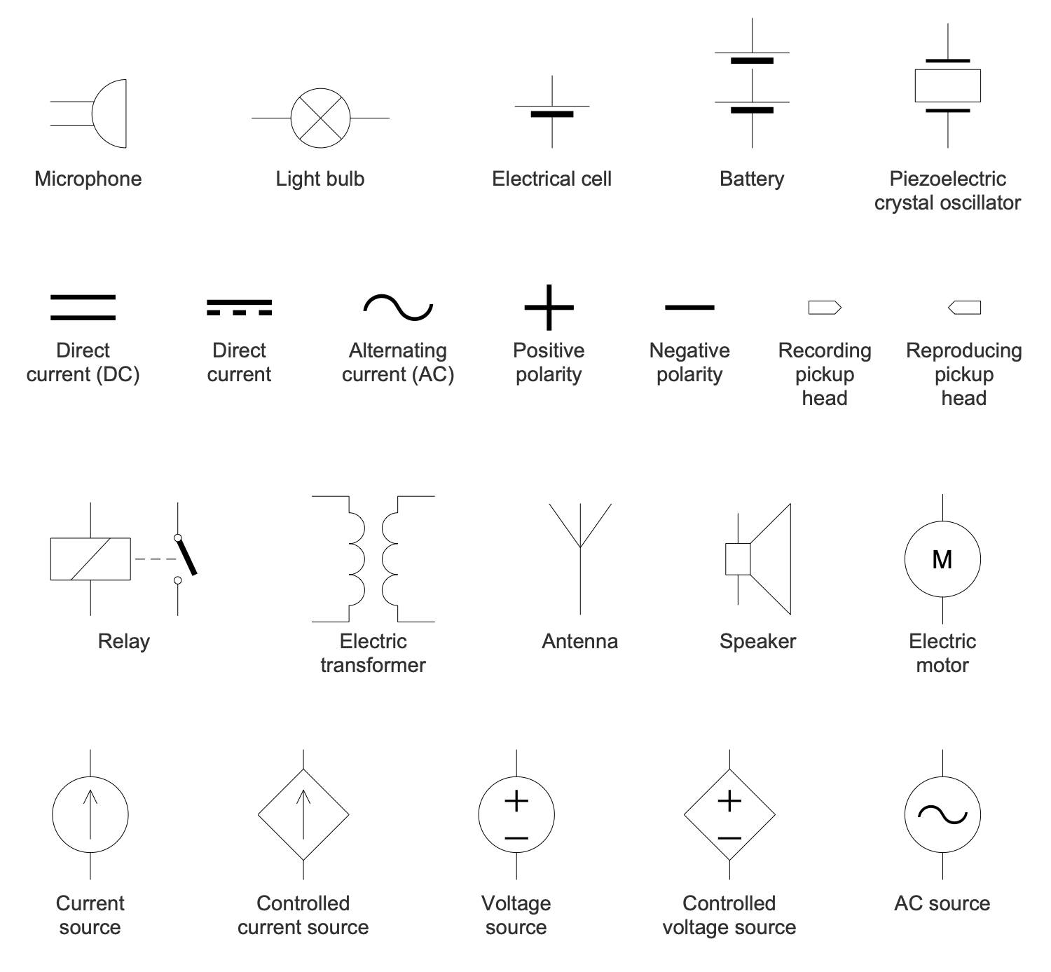
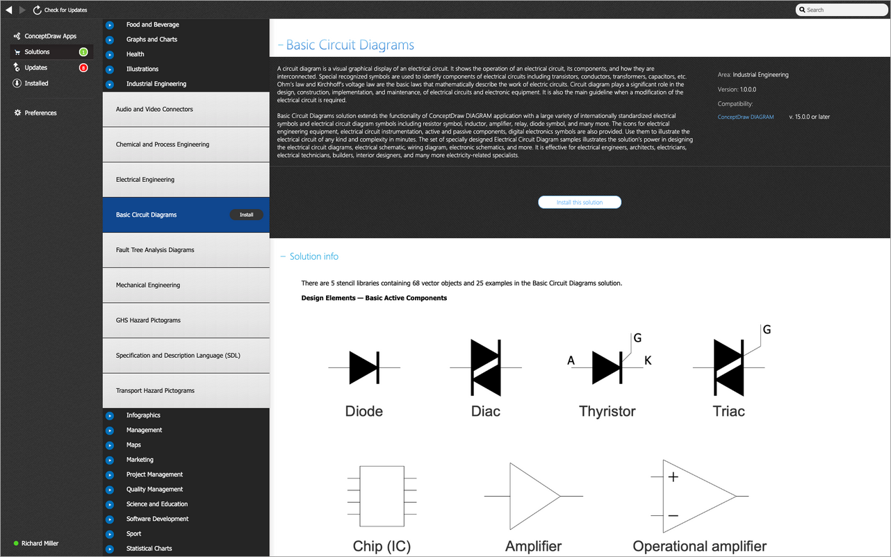
Basic Circuit Diagrams solution extends the functionality of ConceptDraw DIAGRAM application with a large variety of internationally standardized electrical symbols and electrical circuit diagram symbols including resistor symbol, inductor, amplifier, relay, diode symbol, and many more. The icons for electrical engineering equipment, electrical circuit instrumentation, active and passive components, digital electronics symbols are also provided. Use them to illustrate the electrical circuit of any kind and complexity in minutes. The set of specially designed Electrical Circuit Diagram samples illustrates the solution's power in designing the electrical circuit diagrams, electrical schematic, wiring diagram, electronic schematics, and more.
Basic Circuit Diagrams solution is effective for electrical engineers, architects, electricians, electrical technicians, builders, interior designers, and many more electricity-related specialists.
-
What I need to get started -
Solution Requirements - This solution requires the following products to be installed:
ConceptDraw DIAGRAM v18 - This solution requires the following products to be installed:
-
Support for this Solution -
Helpdesk
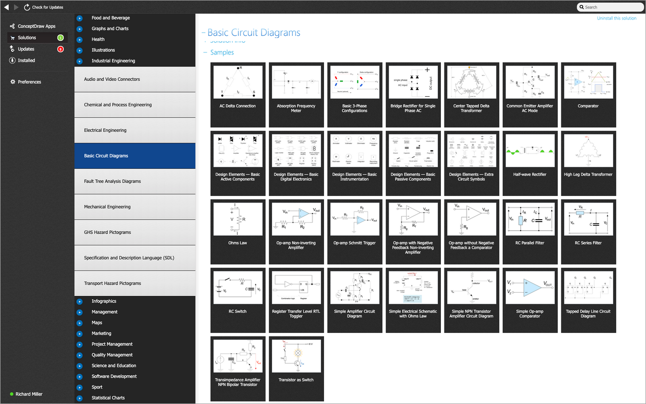
ConceptDraw Basic Circuit Diagrams solution includes 5 libraries containing 68 international standard images and 25 examples.
Design Elements — Basic Active Components

Design Elements — Basic Digital Electronics

Design Elements — Basic Instrumentation

Design Elements — Basic Passive Components
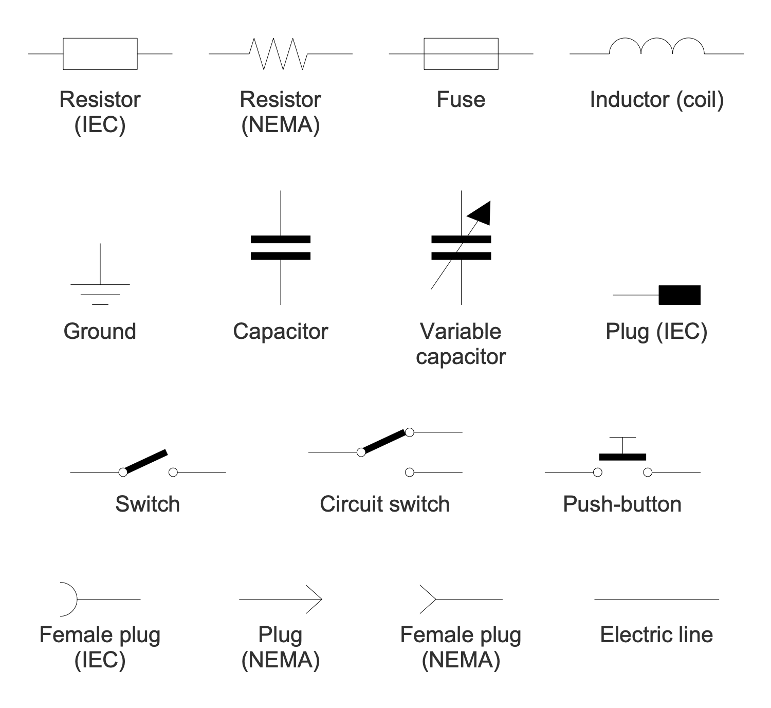
Design Elements — Extra Circuit Symbols
Examples
There are a few samples that you see on this page which were created in the ConceptDraw DIAGRAM application by using the Basic Circuit Diagrams solution. Some of the solution's capabilities as well as the professional results which you can achieve are all demonstrated here on this page.
All source documents are vector graphic documents which are always available for modifying, reviewing and/or converting to many different formats, such as MS PowerPoint, PDF file, MS Visio, and many other graphic ones from the ConceptDraw Solution Park or ConceptDraw STORE. The Basic Circuit Diagrams solutions are available to all ConceptDraw DIAGRAM users to install and use it for working in diagramming and drawing.
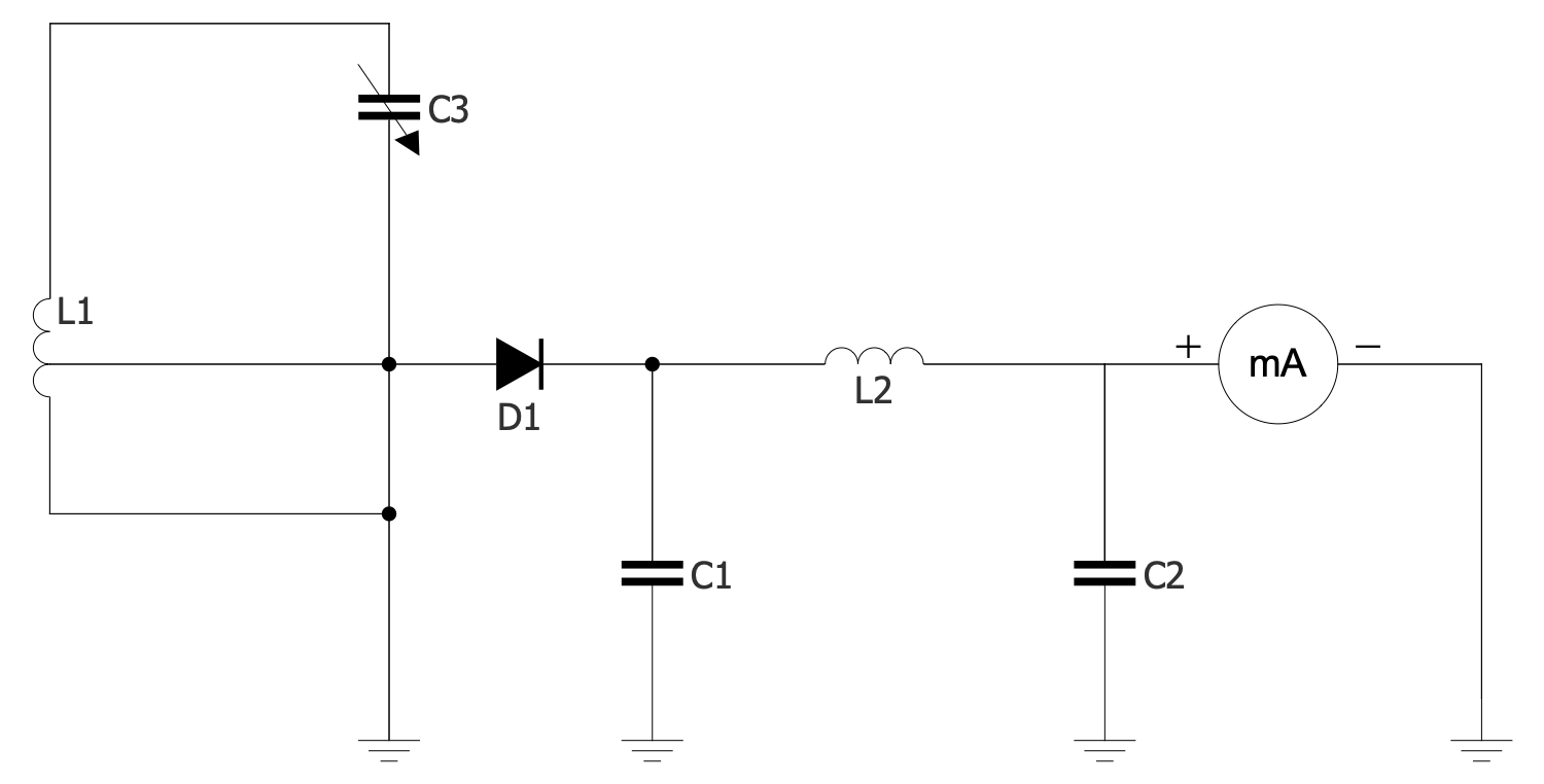
Example 1: Absorption Frequency Meter
This diagram was created in ConceptDraw DIAGRAM using a combination of libraries from the Basic Circuit Diagrams Solution. An experienced user spent 10 minutes creating this sample.
A frequency meter is a special instrument specified to display the frequency of a periodic electrical signal. First frequency meters were mechanical. At the moment, there are several types of digital frequency meters used: vibrating reed meters, moving needle systems, absorption wavemeters, cavity absorption wavemeters, and heterodyne meters. This sample shows an electrical schematic of an absorption frequency meter or absorption wavemeter. This is an electronic instrument applied to measure the frequency of radio waves, to check the output frequency. The absorption wavemeters are loosely related to the radio frequency source but absorb energy from it. The structure of the absorption wavemeter is quite simple, it includes a tunable LC circuit and a separate voltmeter or ammeter. In turn, the LC circuit consists of an inductor and a capacitor connected together and allows measuring high frequencies. The LC circuit is tuned through a variable capacitor and absorbs the energy of the signal until the voltage in the circuit drops.
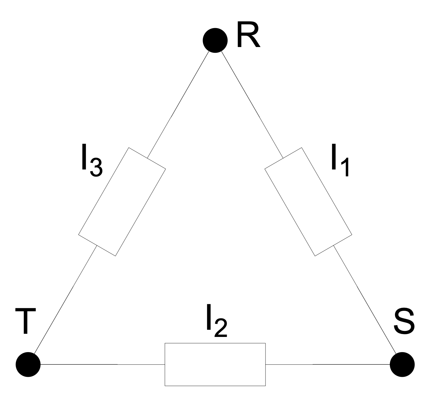
Example 2: AC Delta Connection
This diagram was created in ConceptDraw DIAGRAM using a combination of libraries from the Basic Circuit Diagrams Solution. An experienced user spent 10 minutes creating this sample.
This sample shows AC delta connection applied in three-phase electric power networks. These networks are cost-effective systems when compared with single-phase ones due to the ability to transmit a power three times larger. The networks with the delta connection were developed in the 1880s and today are used all over the world. They contain three wires carrying AC voltages, they are used for electricity transmission and distribution. In fact, it is a symmetric three-phase power supply system. This AC system includes transformers and due to their use, the voltage is changed. It is raised for transmission and vice versa reduced for distribution. A single three-phase transformer or three single-phase transformers are used. The latter is called a closed delta. The finished terminal of one voltage source (winding) is connected to the start terminal of another one. You can see that in a delta configuration, every two windings are pairwise connected.
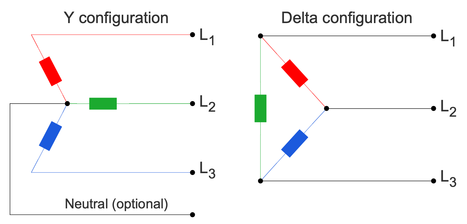
Example 3: Basic 3-Phase Configurations
This diagram was created in ConceptDraw DIAGRAM using a combination of libraries from the Basic Circuit Diagrams Solution. An experienced user spent 10 minutes creating this sample.
This sample shows two basic three-phase electric power configurations: Y (wye or star) and delta. A delta configuration uses three wires for transmission while a wye configuration may also have a fourth wire — neutral or optional. The wires are connected to a common connection point. The delta configuration is valued for the fault tolerance, its voltage or current is constant regardless of the failures in the load elements. The neutral wire in the Y configuration is commonly grounded and does not carry current. It is provided for fault protection and helps avoid problems in the case of failing one of the three elements in a system. One differs the symmetrical and non-symmetrical four-wire systems. When the neutral is connected to the "common star point" of the supply windings, all three phases have the same voltage relative to the neutral. This system is called "symmetrical". In practical use, the electrical engineers strive to balance the load between three phases, to distribute it evenly. The load at the point of supply also should be balanced.
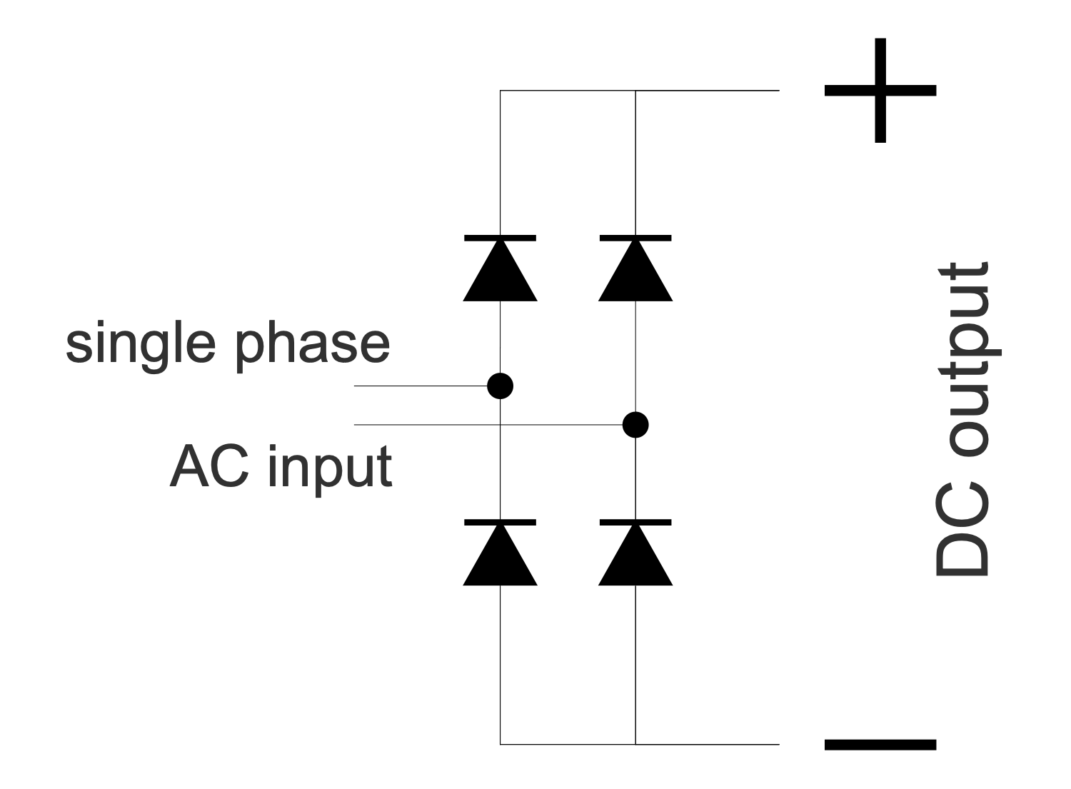
Example 4: Bridge Rectifier for Single Phase AC
This diagram was created in ConceptDraw DIAGRAM using a combination of libraries from the Basic Circuit Diagrams Solution. An experienced user spent 10 minutes creating this sample.
This sample shows a bridge rectifier for single-phase AC. A rectifier of any kind allows straightening the direction of the current. This electrical device converts alternating current (AC) to direct current (DC). AC is characterized by changing direction while DC flows only in one direction. Two types of rectifier circuits are used: single-phase for domestic use and multi-phase for industrial application. The special semiconductor diodes are used to straighten the current. Sometimes the additional smoothing is required to receive a uniform steady voltage; the capacitors and chokes are used for that purpose. The bridge rectifier in a single-phase circuit has a connection to one of the AC contacts and the load is supplied to the other side of the diagonal. In this circuit, the diodes work in pairs. In one direction, the current flows from the secondary winding, in other — along the circuit. Switching occurs when the alternating voltage passes through neutral.
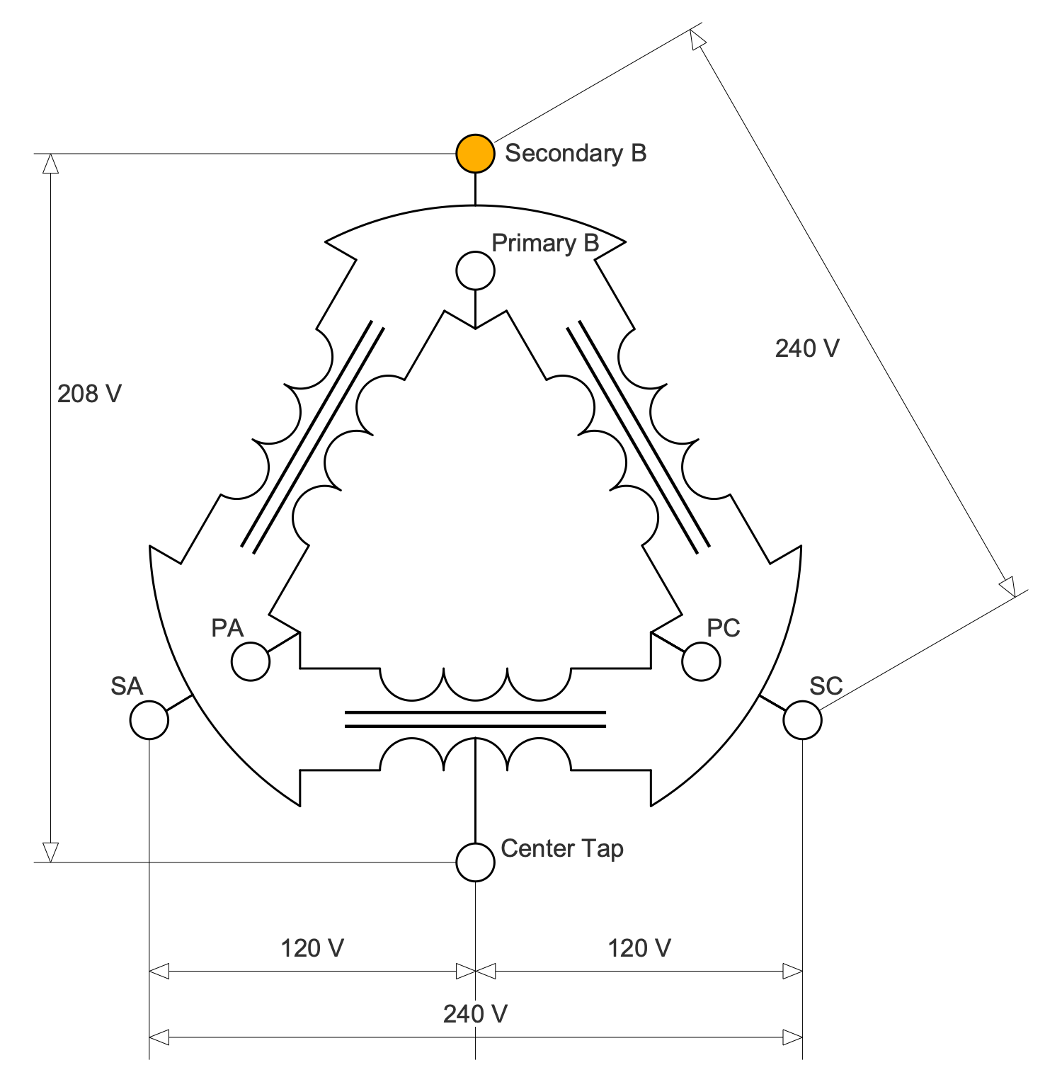
Example 5: Center Tapped Delta Transformer
This diagram was created in ConceptDraw DIAGRAM using a combination of libraries from the Basic Circuit Diagrams Solution. An experienced user spent 10 minutes creating this sample.
This electrical engineering sample shows a center-tapped delta transformer used to transform the 3-phase power to a split phase. These transformers are widely used in industrial regions, commercial, and high-density residential areas. The three-phase power is connected in the delta configuration and the center point of one phase is grounded. The 3-phase transformer or three single-phase transformer include four wires — three phase wires and one neutral. The neutral wire is connected as a center tap on one of the windings. The voltages between the phases A-B, B-C, and C-A are the same and equal to 240 volts. However, the voltage magnitudes between the neutral and each phase significantly vary. The voltage between phase A and neutral equals to the voltage between phase C and neutral. Both are equal to half the line voltage, which is 120 volts. The voltage between phase B and neutral is 208 volts. Create your own diagram in minutes using pre-made electrical symbols from solution libraries, or modify one of the existing samples to suit your needs.
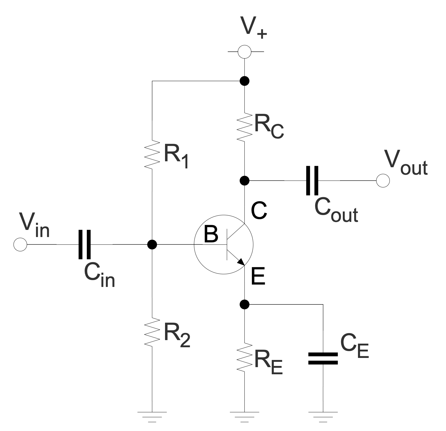
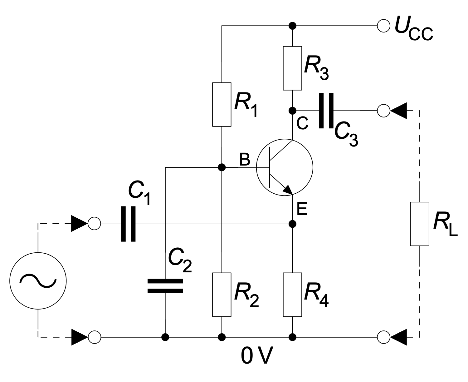
Example 6: Common Emitter Amplifier AC Mode
This diagram was created in ConceptDraw DIAGRAM using a combination of libraries from the Basic Circuit Diagrams Solution. An experienced user spent 10 minutes creating this sample.
This sample shows a center-tapped delta transformer used to converse the 3-phase power to the split phase. The three-phase power is connected in the delta configuration, the center point of one phase is grounded. These transformers are widely used in industrial and commercial regions and high-density residential areas. 3-phase transformer or three single-phase transformers include four wires coming out of the secondary winding. These are three phase wires and one neutral connected as a center tap on one of the windings. The voltages between the three phases are equal in magnitude. But the voltage magnitudes between the neutral and each phase significantly vary. The voltage from phase to phase A-B, B-C, and C-A equals 240 volts each. The voltage between A phase and neutral equals to one between C phase and neutral. Because of the center-tapped in winding between A and C phases, they both equal half of the voltage A-C, it is 120 volts. Meanwhile, the voltage between B phase and neutral equals 208 volts.
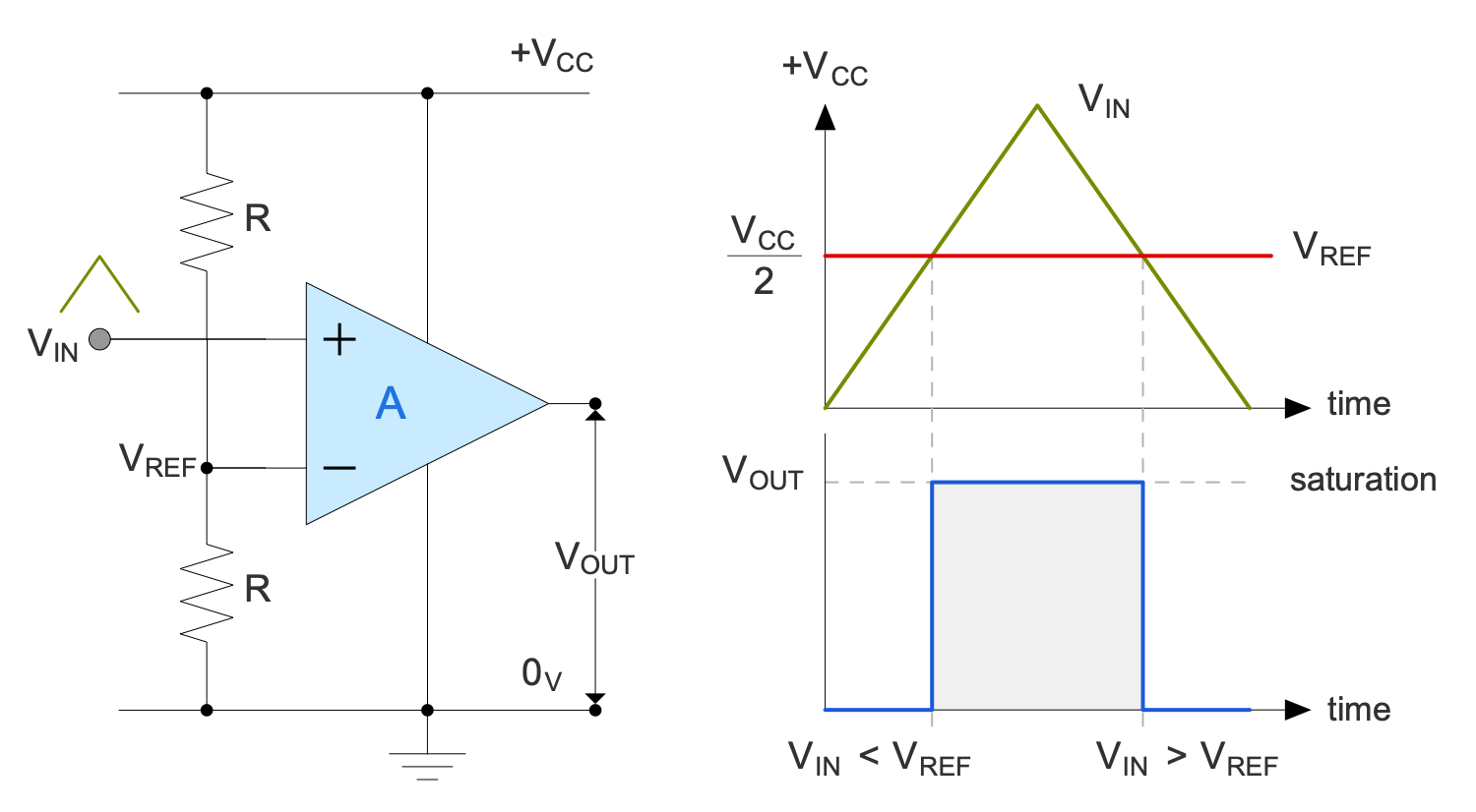
Example 7: Comparator
This diagram was created in ConceptDraw DIAGRAM using a combination of libraries from the Basic Circuit Diagrams Solution. An experienced user spent 10 minutes creating this sample.
This sample illustrates the work of a comparator. This device is used to compare two voltages or currents, it outputs a binary digital signal 1 or 0. The value 1 corresponds to the voltage at the plus side and 0 to the voltage at the negative side. This signal indicates which voltage or current is larger. A comparator has two analog input terminals and one binary digital output. It commonly includes a specialized high-gain differential amplifier. This sample shows a simple operational amplifier (op-amp) comparator. It has a high gain and well-balanced difference input. Op-amp operates in the linear mode and there is no inverse relationship. The voltage difference between Vin and Vref is amplified. The comparator outputs the resulting Vout. If Vin is greater than Vref, then the voltage on Vout rises to the voltage on the positive side, otherwise, it drops to the voltage on the negative side.
Example 8: Half-wave Rectifier
This diagram was created in ConceptDraw DIAGRAM using a combination of libraries from the Basic Circuit Diagrams Solution. An experienced user spent 10 minutes creating this sample.
This sample shows a single-phase half-wave rectifier circuit and two graphs. The first graph shows the voltage versus time before rectification, and the second after it. The half-wave rectifier includes only one rectifier element — a diode. At the output, we have a pulsating direct current. Single-phase half-wave rectifiers are widely used in modern household and industrial equipment in switching power supplies with an alternating voltage frequency of more than 10 kHz. A single positive or negative half of the AC waveform passes through the half-wave rectifiers and reaches the output, the other half is blocked. As a result, the average voltage is lower. The advantage of using a half-wave rectifier is the savings in the number of valves, voltage drop and power loss in the rectifier. However, the main disadvantages are a large number of pulsations and a strong load on the reinforcement.

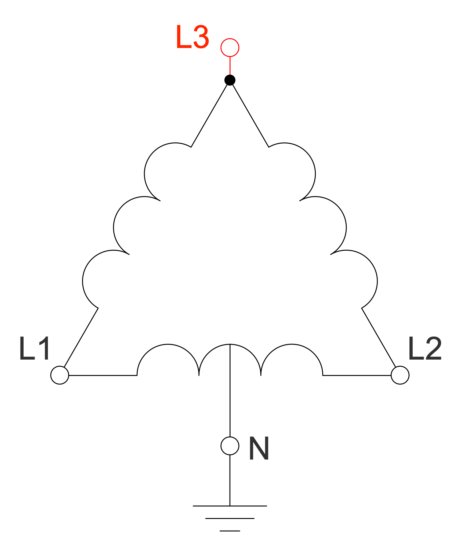
Example 9: High Leg Delta Transformer
This diagram was created in ConceptDraw DIAGRAM using a combination of libraries from the Basic Circuit Diagrams Solution. An experienced user spent 10 minutes creating this sample.
This sample shows a schematic of a high leg delta or orange-leg transformer. The "orange leg" name was taken from the orange color of the wire. This transformer is an extension of a split-phase electric power transformer for three phases. This mixed system is used in three-phase electric power installations to connect both the single-phase and three-phase loads. The 3-phase transformer includes four wires coming out of the secondary. These are three phases and one neutral connected as a center tap. The voltage magnitudes are the same between the three phases and differ between a specific phase and a neutral. Three-phase loads are connected in delta configuration to L1, L2, and L3 phases. The center point of one of the phases is grounded. The single-phase loads are connected between L1 and L2, L1 and neutral, or L2 and neutral. The L3 phase isn't used for single-phase loads.
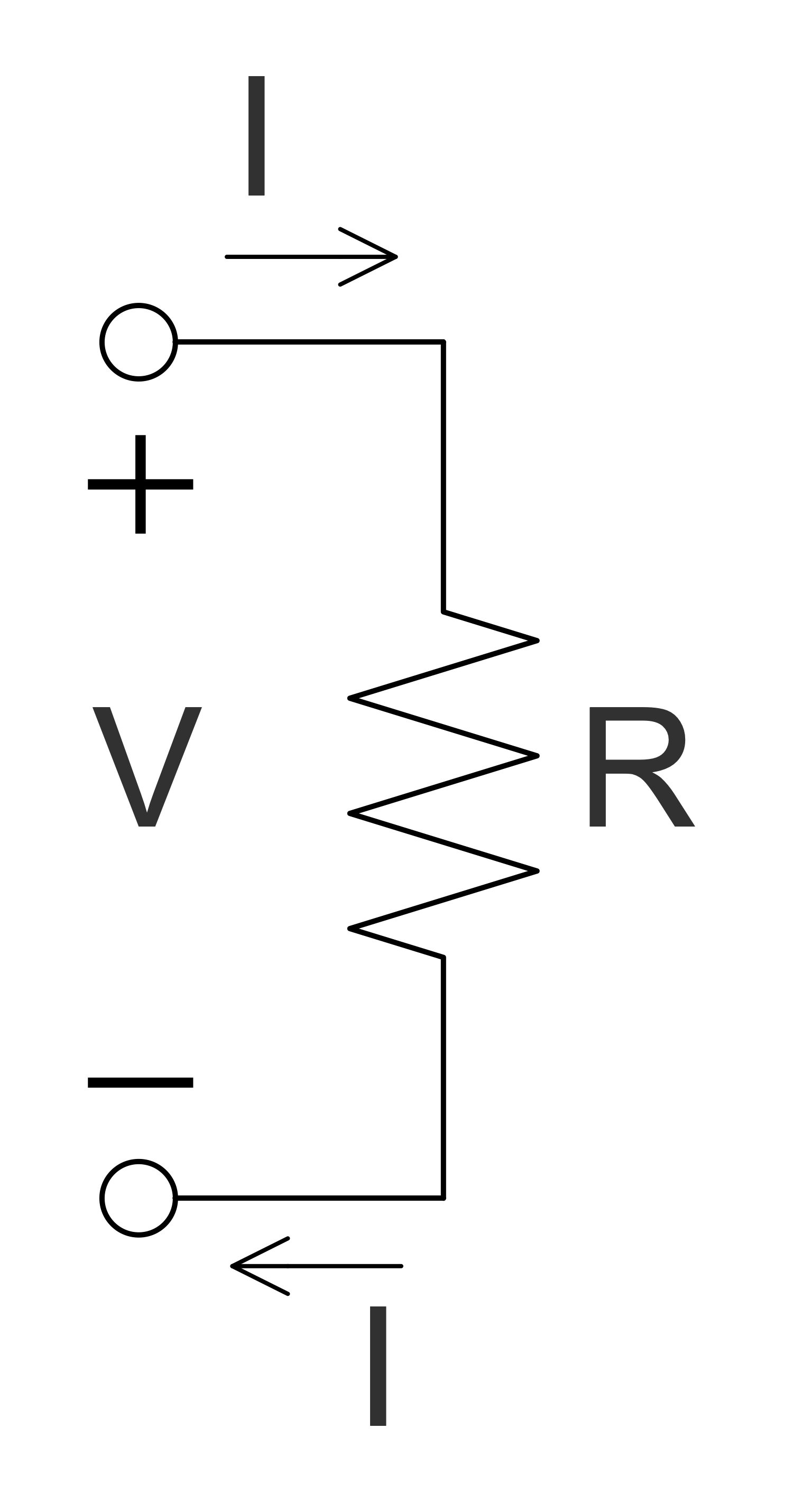
Example 10: Ohms Law
This diagram was created in ConceptDraw DIAGRAM using a combination of libraries from the Basic Circuit Diagrams Solution. An experienced user spent 10 minutes creating this sample.
This sample is an illustration of Ohm's law, established by the German physicist Georg Ohm in 1827. It determines the empirical relationship between the parameters of voltage (V), current (I) and resistance (R) in an electrical circuit and is described as follows: the formula I=V/R. Ohm's law says: the current between two points of the circuit is directly proportional to the voltage at these points and is inversely proportional to its resistance. R in this relation is constant and independent of the current, it is determined by the physical and geometric parameters of the conductor. Ohm's law describes the conductivity of most of electrically conductive materials called ohmic. And only a little number of materials do not obey Ohm's law and are called non-ohmic. Ohm's law also isn't observed at low temperatures for substances with superconductivity, in vacuum and gas-filled electronic lamps, at high frequencies when high voltage is applied to a conductor or dielectric, at the conductor's heating by a passing current, and in some other cases.
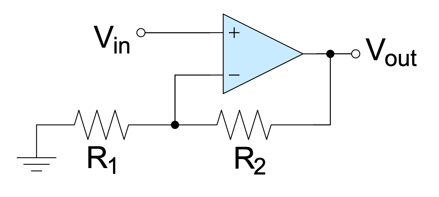
Example 11: Op-amp Non-inverting Amplifier
This diagram was created in ConceptDraw DIAGRAM using a combination of libraries from the Basic Circuit Diagrams Solution. An experienced user spent 10 minutes creating this sample.
This sample shows a non-inverting amplifier and is a special case of the differential amplifier. The circuit includes the grounded inverting input Vin and allows achieving the non-inverted output Vout at the final stage. The resistors R1 and R2 form a voltage divider. The amplified signal is delivered to the non-inverting input of the operational amplifier. The signal from the output enters the inverting input through the voltage divider. The op-amp processes the input so that the voltage at the inverting input is equal to the voltage at the non-inverting input. The output voltage changes in the same direction as the input voltage. The non-inverting amplifier is a popular type of amplifier and is preferred in many cases. However, it is required to connect the additional equipment for further inverting the inverted output. And the resistance at the input depends on the resistor connected there.
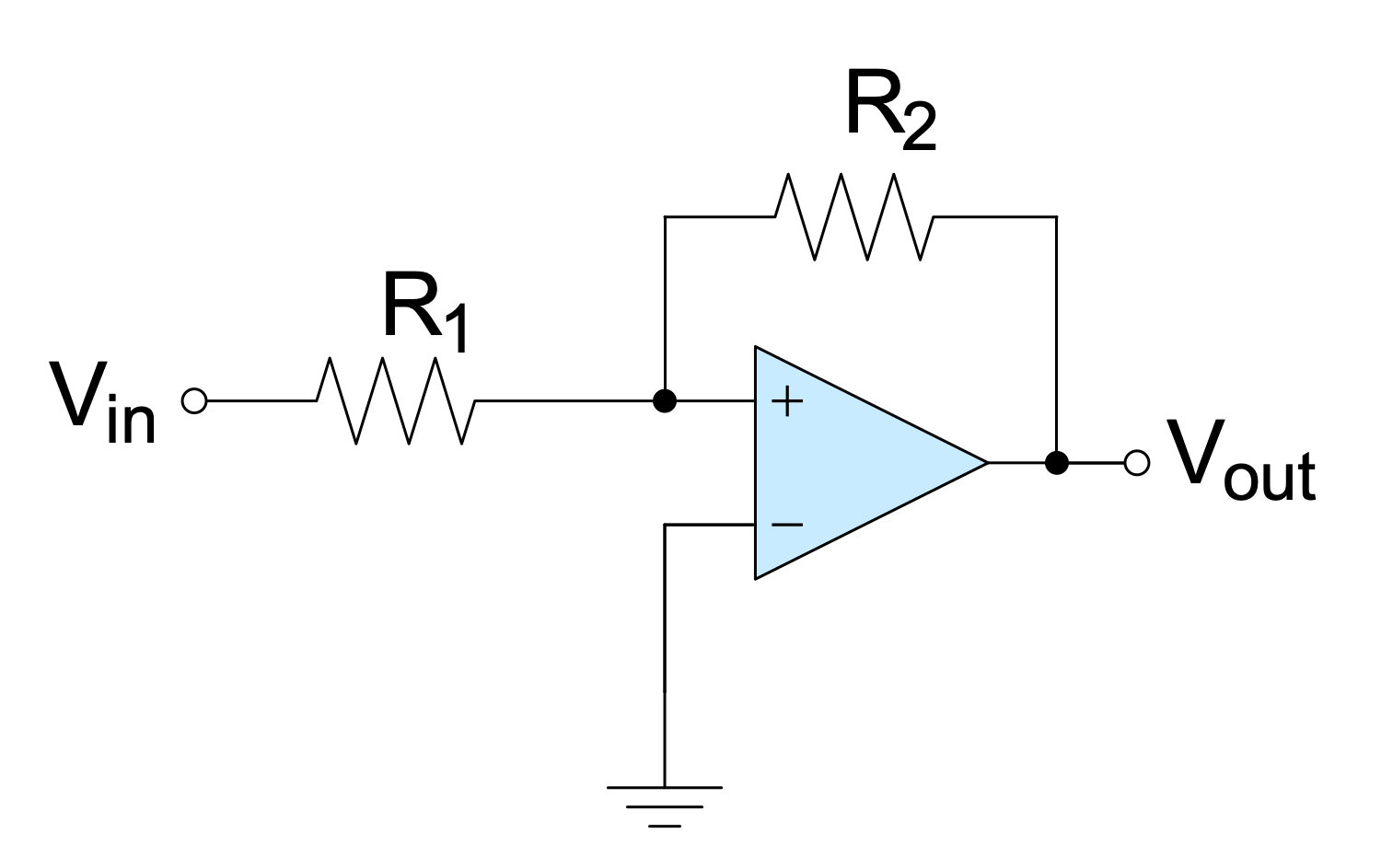
Example 12: Op-amp Schmitt Trigger
This diagram was created in ConceptDraw DIAGRAM using a combination of libraries from the Basic Circuit Diagrams Solution. An experienced user spent 10 minutes creating this sample.
This sample shows a Schmitt trigger created using an operational amplifier connected in the non-inverting amplifier configuration. It is applied to convert an analog input signal to a digital output signal. Op-amps are DC-coupled high-gain electronic voltage amplifiers. In common, they include a differential input and a single-ended output. These units are widely used in different electronic devices today, including industrial and scientific devices. Schmitt triggers are the comparator circuits with hysteresis. The positive feedback is applied to the non-inverting input of a comparator, differential amplifier, or op-amp as in a given case. The output holds its value until the changes caused by input occur. Schmitt triggers possess memory and are often applied in devices to remove noise from signals used in digital circuits, in closed-loop negative feedback configurations. They are included in relaxation oscillators, which are part of switching power supplies and function generators.
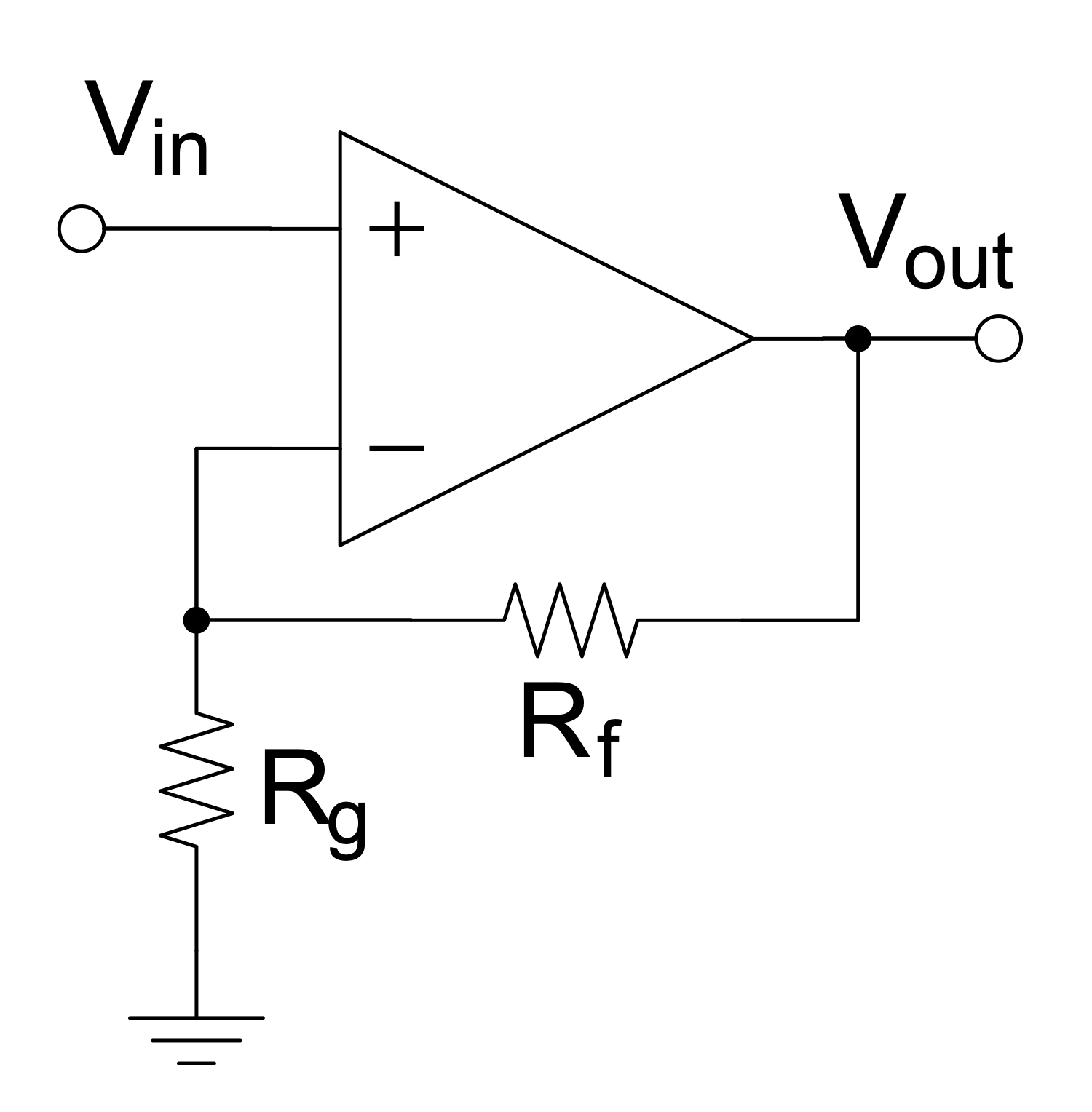
Example 13: Op-amp with Negative Feedback Non-inverting Amplifier
This diagram was created in ConceptDraw DIAGRAM using a combination of libraries from the Basic Circuit Diagrams Solution. An experienced user spent 10 minutes creating this sample.
This sample shows the non-inverting amplifier with negative feedback. Negative feedback occurs when some function of the output reduces the fluctuations in the output when it is fed back. The op-amp is most often used in the negative feedback mode and allows controlling the output. Negative feedback stabilizes the gain and increases bandwidth. Frequency distortion, noise, and non-linear distortion are reduced also due to negative feedback in op-amp. The input voltage is applied to the non-inverting input, the output signal is not inverted with respect to the input and coincides in phase. The non-inverting input has V+ voltage and the inverting input has V− voltage. The op-amp amplifies this difference in voltages called the differential input voltage. The input and output voltages have the same polarity in the non-inverting amplifier with negative feedback. The inverting input is grounded via resistor Rg. Resistance Rf plays the role of negative feedback.
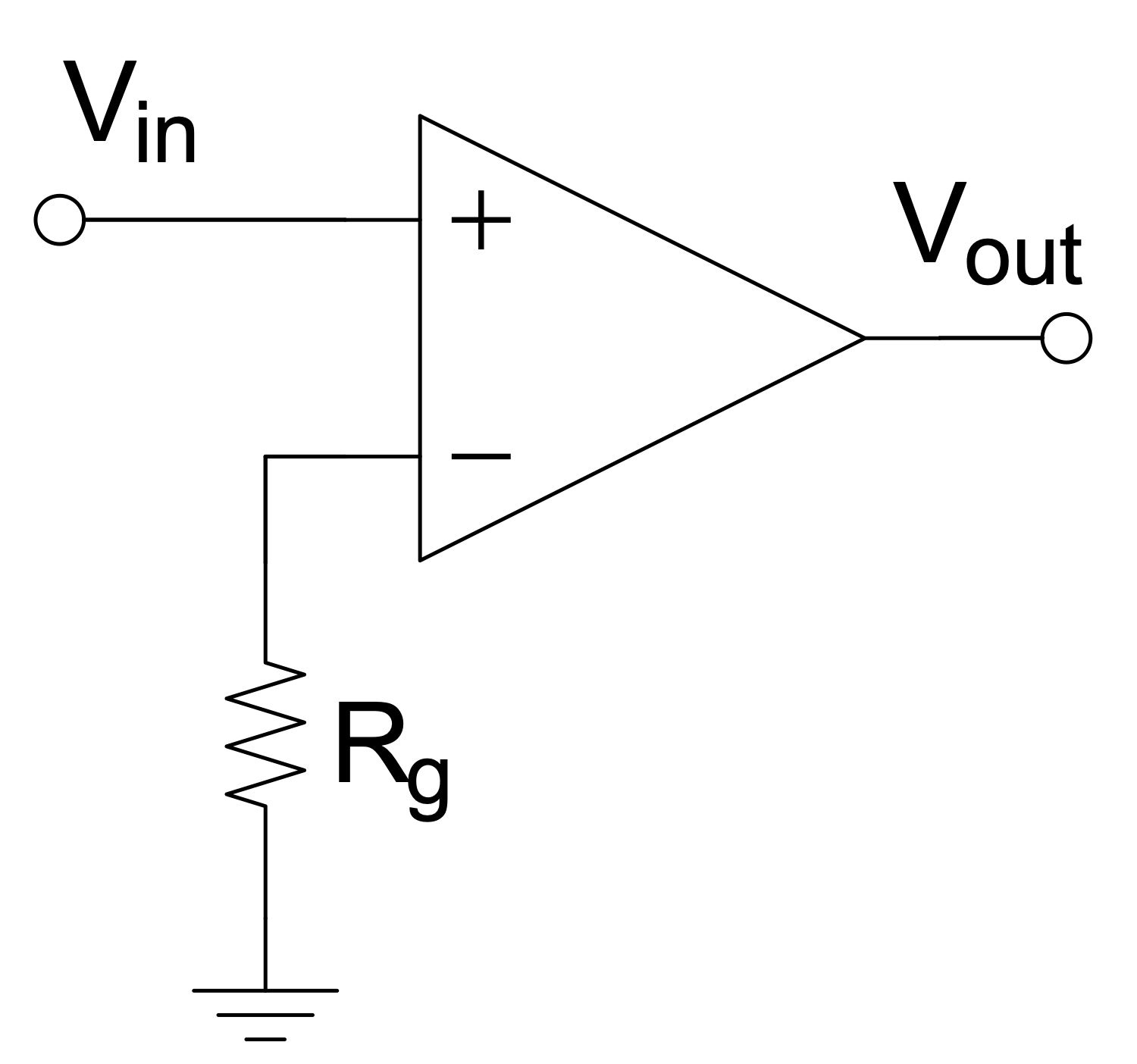
Example 14: Op-amp without Negative Feedback a Comparator
This diagram was created in ConceptDraw DIAGRAM using a combination of libraries from the Basic Circuit Diagrams Solution. An experienced user spent 10 minutes creating this sample.
This Circuit diagram sample shows the operational amplifier with one input grounded and no negative feedback. This kind of op-amp is called a comparator. It includes the inverting input and non-inverting input. The comparator compares the voltage entering at one of its inputs with the reference voltage at its other input. When the input voltage coming to the inverted input is greater than the reference voltage coming to the non-inverting input, the output voltage takes the value of the negative saturation voltage. At the same time, it remains unchanged until the input voltage decreases below the reference voltage. In this case, the output voltage will have positive saturation. When the inverting input is grounded and the input voltage Vin applied to the non-inverting input is positive, the output will be positive. At the negative Vin, the output will be also negative. Designing of any Circuit diagram or Wiring diagram isn’t a difficult task with ConceptDraw DIAGRAM software, try and make sure this.
Example 15: RC Parallel Filter
This diagram was created in ConceptDraw DIAGRAM using a combination of libraries from the Basic Circuit Diagrams Solution. An experienced user spent 10 minutes creating this sample.
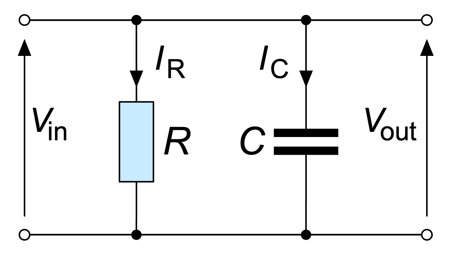
This sample shows a schematic of a parallel resistor-capacitor (RC) filter. It is an electric circuit including one resistor and one capacitor and driven by a voltage or current source. The resistor and capacitor are depicted using a resistor symbol and capacitor symbol correspondingly from the solution libraries. This sample shows a first order RC circuit. RC circuits of other orders include more capacitors and resistors. RC circuits are widely used in radio electronics. Typically, they are applied to filter signals. There are high-pass and low-pass filters, band-pass and band-stop filters. RC filters block certain frequencies and pass other ones. In the parallel RC circuit, the output voltage Vout is equal to the input voltage Vin. It works as a filter of the input signal. All kinds of resistor-capacitor filters including filters of second, third, fourth order of different designation are easily designed in ConceptDraw DIAGRAM software. Try to create your own schematic right now and ensure how simply it is.
Example 16: RC Series Filter
This diagram was created in ConceptDraw DIAGRAM using a combination of libraries from the Basic Circuit Diagrams Solution. An experienced user spent 10 minutes creating this sample.
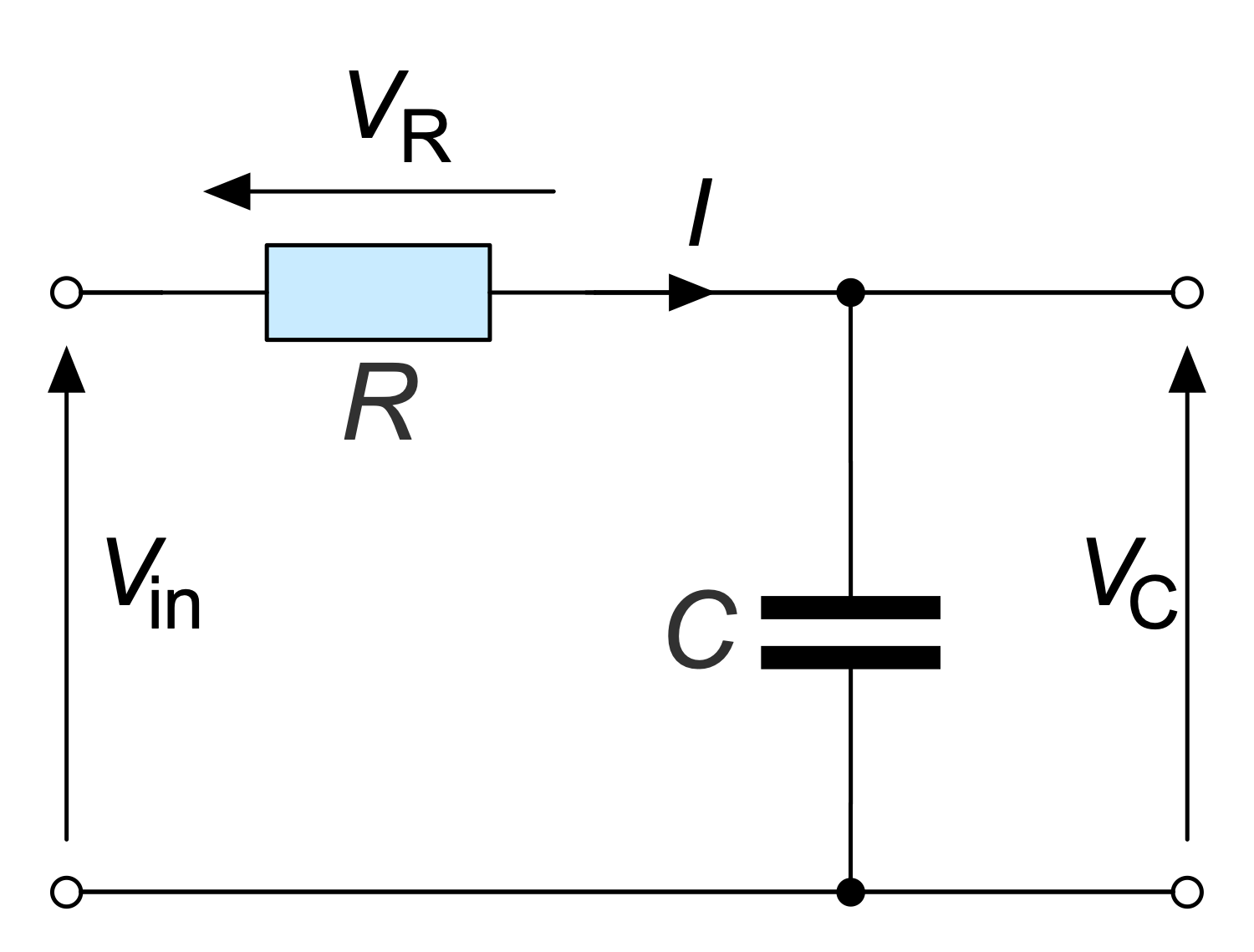
This sample shows a series RC filter. A series circuit is also called a daisy chain-coupled or current-coupled circuit. The schematic includes a resistor R and a capacitor C. The current I in the series circuit flows only in one direction and passes through each component of this circuit. That's why all of the elements carry the same current and opening or breaking a series circuit at some point causes the stop in operating of the entire circuit. The input voltage Vin, the voltage across the resistor Vr, and the voltage across the capacitor Vc are also shown in the diagram. This RC filter is the low-pass filter. It suppresses all frequencies of the input signal above the cutoff frequency and passes unchanged all frequencies below it. The low frequencies are skipped and high frequencies are blocked. And there is no transition zone between frequencies for which the filter does not cause significant attenuation (passband) and for which causes (stopband).
Example 17: RC Switch
This diagram was created in ConceptDraw DIAGRAM using a combination of libraries from the Basic Circuit Diagrams Solution. An experienced user spent 10 minutes creating this sample.
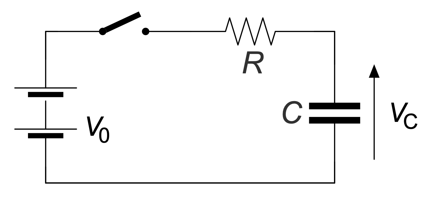
This sample shows a simple resistor-capacitor (RC) circuit used for charging a capacitor. This circuit contains a resistor, a capacitor, a switch, and a source of voltage V0. The electrical capacity or ability to accumulate and retain an electric charge is the capacitor's main characteristic. Because the greater electric charge it collects, the greater charge it later gives to the external electrical circuit when discharged. When the switch is closed, free electrons move, a current arises in the circuit and the capacitor begins to charge. The process of its charging will continue until the voltage on it becomes equal to the voltage of the source. When the accumulated charge becomes equal to the multiplication of the capacitor's volume and steady-state voltage, then no current will be in the circuit and the capacitor will be fully charged. The volume of the capacitor and the resistance of the circuit determine the duration of the charging process.
Example 18: Register Transfer Level RTL Toggler
This diagram was created in ConceptDraw DIAGRAM using a combination of libraries from the Basic Circuit Diagrams Solution. An experienced user spent 10 minutes creating this sample.
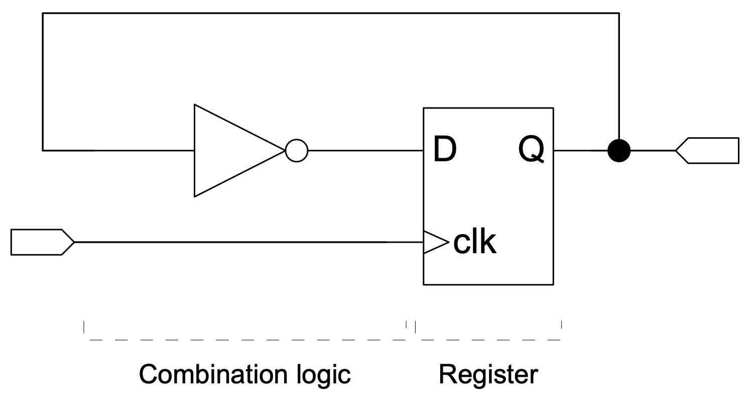
This sample shows a Register Transfer Level (RTL) switch circuit. The circuit consists of two kinds of elements: combinational logic, formed by an inverter, and sequential logic, represented by a register. The inverter is connected from the register output (Q) to its input (D). Registers store state and have memory properties. Combinational logic performs logic functions in a circuit and consists of logic gates. The output toggles every rising edge of the input. The Register Transfer Layer (RTL) is used in Hardware Description Languages (HDL) to create high-level representations of a circuit. This level is used in modern digital design at the stage of logical design of an integrated circuit. This allows circuit designers to simulate a synchronous digital circuit and display the digital signal flow between hardware registers and the logical operations they perform. Schema designers use HDL to declare registers and describe combinational logic and arithmetic operations.
Example 19: Simple Amplifier Circuit Diagram
This diagram was created in ConceptDraw DIAGRAM using a combination of libraries from the Basic Circuit Diagrams Solution. An experienced user spent 10 minutes creating this sample.
This diagram shows the use of a simple amplifier in an analog circuit. An amplifier is an electronic device that uses electricity from a power source to increase signal capacity. It is a separate piece of equipment or an electrical circuit contained in another device. Amplifiers are classified by electronic signal frequency and physical location in the signal chain and are used in almost all electronic devices. An analog circuit is a circuit with a current or voltage that continuously changes over time according to information. An analog circuit has two main building blocks: serial and parallel circuits. In a parallel circuit, all components are connected to the same voltage, and the current is divided between the components according to their resistance. And the same current flows through all the components in the series circuit.
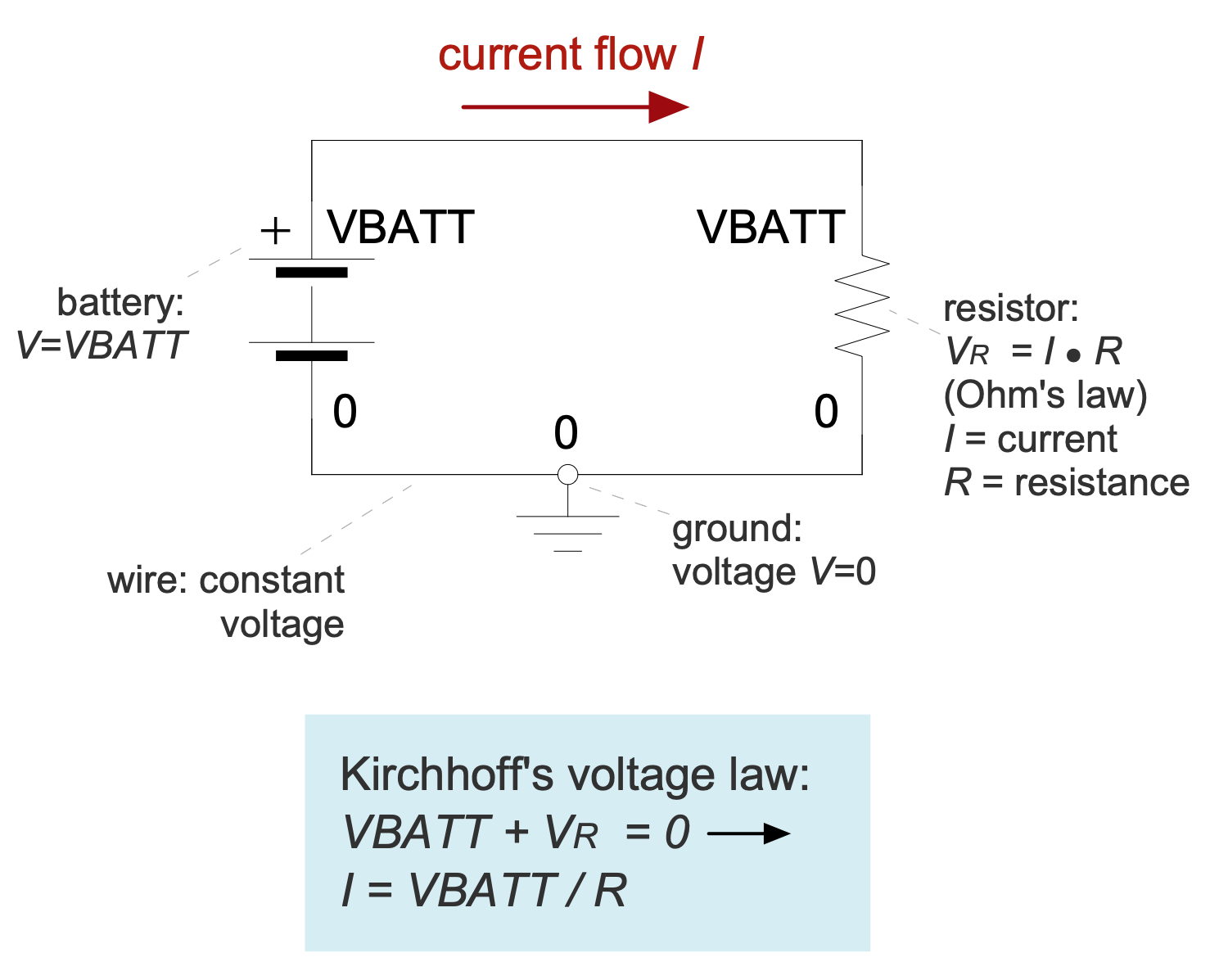
Example 20: Simple Electrical Schematic with Ohms Law
This diagram was created in ConceptDraw DIAGRAM using a combination of libraries from the Basic Circuit Diagrams Solution. An experienced user spent 10 minutes creating this sample.
This simple circuit diagram shows the use of Ohm's law and Kirchhoff's voltage law to find the current. Ohm's law was discovered and published by Georg Simon Ohm in 1827. It is presented by Vr=I*R formula and says that the current through a conductor between two points is directly proportional to the voltage across these points. Kirchhoff's voltage law was discovered by Gustav R. Kirchhoff in 1847. It states that the algebraic sum of all voltages in a loop must equal zero, here Vbatt+Vr=0. This electronic circuit includes a battery, a resistor, and wires. The wires are interconnections with a constant zero voltage and are shown as lines in a diagram. All other components are presented using their common symbols. The circuit is grounded (voltage V=0). The direct current flows from plus to minus. The additional comments in a form of legend are also reasonable in this diagram.
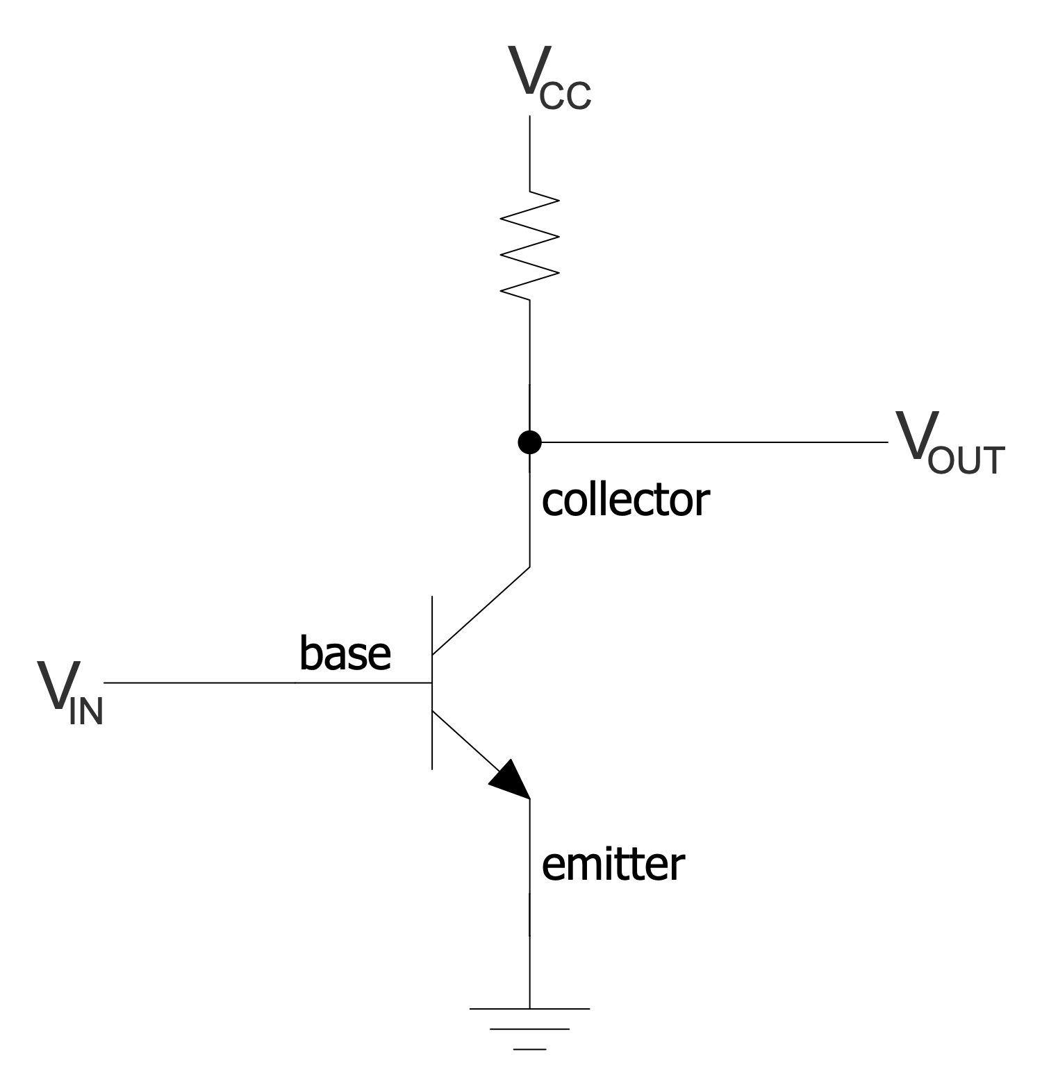
Example 21: Simple NPN Transistor Amplifier Circuit Diagram
This diagram was created in ConceptDraw DIAGRAM using a combination of libraries from the Basic Circuit Diagrams Solution. An experienced user spent 10 minutes creating this sample.
This sample shows a simple bipolar NPN transistor amplifier circuit diagram with transistor labels. A bipolar transistor is an electronic semiconductor device, one of the kinds of transistors. It is developed to amplify, generate and convert electrical signals. The first bipolar junction transistor was invented by Bell Labs' William Shockley in 1948. A little later a bipolar NPN junction amplifying germanium transistor was developed. The transistor is made of three semiconductor layers and has free carriers of both positive (p) and negative (n) charges. The bipolar transistor of NPN configuration is based on two p-n junctions and has two n charges and one p charge, i.e. the number of negative charges prevails. Each bipolar transistor has three contacts (electrodes) — base, emitter, and collector. The base layer is thin relative to the collector and emitter ones. A large number of pre-made electrical circuit symbols including diode symbol, conductor, amplifier, and more from the Basic Circuit Diagrams solution helps to create schematics of any configuration.
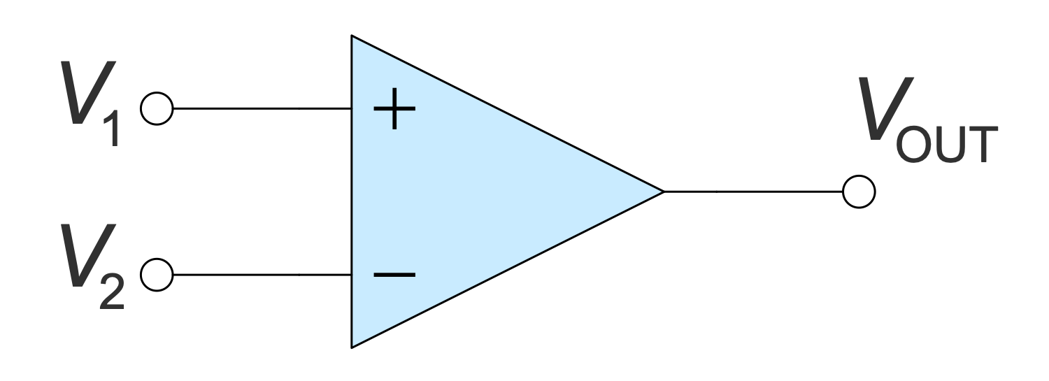
Example 22: Simple Op-amp Comparator
This diagram was created in ConceptDraw DIAGRAM using a combination of libraries from the Basic Circuit Diagrams Solution. An experienced user spent 10 minutes creating this sample.
This sample shows a comparator based on a simple operational amplifier (op-amp). A comparator is a device that takes two analog signals as input, compares them and outputs a 1 or 0. The comparator indicates which one is greater, or checks if the input has reached some predetermined value. Comparators are used in various electronic devices, alarm and access control equipment, etc. An operational amplifier is a differential input DC amplifier, usually with a single high gain output. Nowadays, operational amplifiers are widely used both as individual microcircuits and as functional blocks of more complex integrated circuits. Operational amplifiers have the same characteristics as comparators, which is why operational amplifiers are often used as comparators in devices with low performance requirements. Create your own detailed configurations using comparators or op-amps with ease in ConceptDraw DIAGRAM.
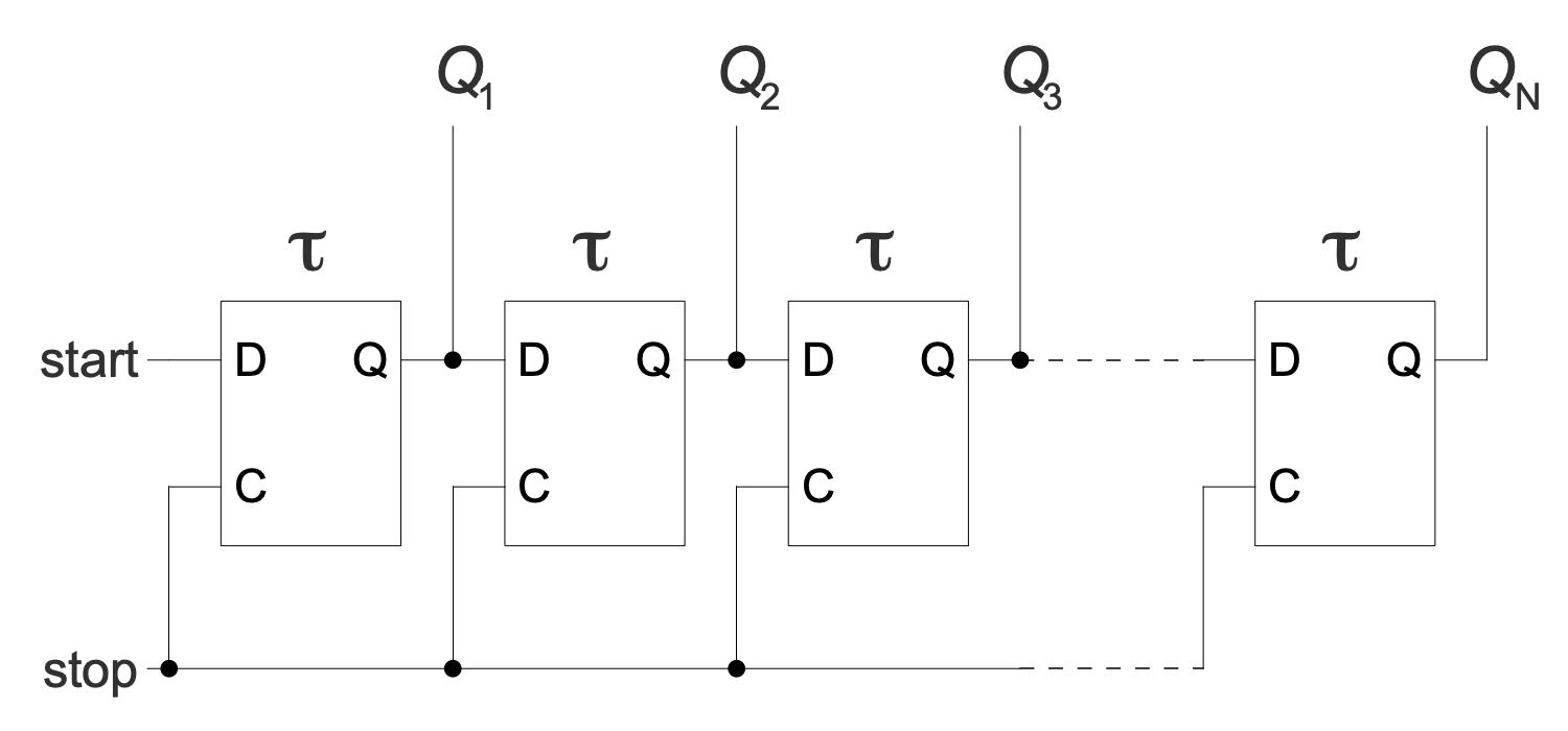
Example 23: Tapped Delay Line Circuit Diagram
This diagram was created in ConceptDraw DIAGRAM using a combination of libraries from the Basic Circuit Diagrams Solution. An experienced user spent 10 minutes creating this sample.
This Circuit diagram sample shows a tapped delay line. A delay line is a device developed to delay electrical, electromagnetic, or optical signals for a specified period of time. It includes a set of cells with well-defined delay times. They are shown as rectangles on a diagram. The signal starts at the start point and spreads through this line. From time to time it stops and is delayed for a certain number of operations. The delay time is proportional to the length of the line. This is implemented with a time delay D flip-flop cell ruler. The output of each trigger will be sampled. The stop light fixes all triggers. As for the application, the delay lines are widely used in radio electronics, radar and radio navigation equipment, color televisions of PAL and SECAM standards, measuring and communication equipment, electroacoustics, etc.
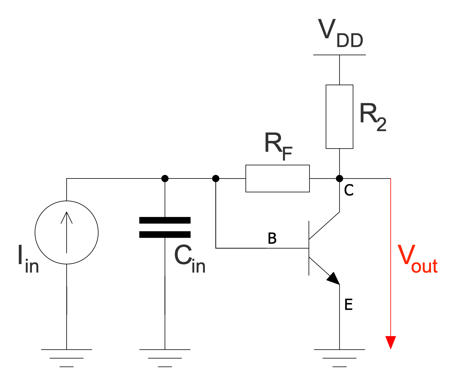
Example 24: Transimpedance Amplifier NPN Bipolar Transistor
This diagram was created in ConceptDraw DIAGRAM using a combination of libraries from the Basic Circuit Diagrams Solution. An experienced user spent 10 minutes creating this sample.
This diagram shows a transimpedance amplifier (TIA) created with an NPN bipolar transistor. It is a current-to-voltage converter. There are different configurations of transimpedance amplifiers depending on their application. Typically, a transimpedance amplifier includes one or more operational amplifiers and a feedback resistor (Rf). In an inverting configuration, this resistor has a -Rf value. TIA is used to convert the low-level output current of various types of sensors into useful voltages, for example, accelerometers, Geiger-Muller tubes, photodetectors, photomultiplier tubes with photodiodes. The transimpedance amplifier provides low photodiode impedance. Various specifications including gain, bandwidth, current and voltage offset also depend on the sensor type. Use bright colors to highlight important points in the diagram and to grab the attention of stakeholders.
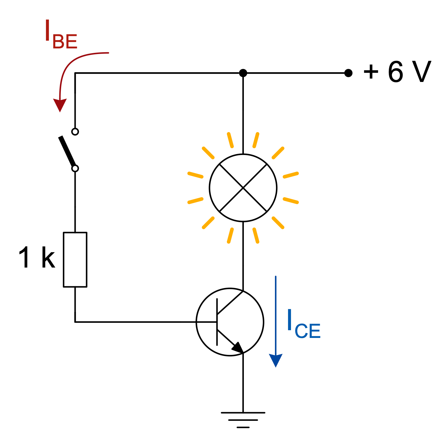
Example 25: Transistor as Switch
This diagram was created in ConceptDraw DIAGRAM using a combination of libraries from the Basic Circuit Diagrams Solution. An experienced user spent 10 minutes creating this sample.
This sample shows a bipolar junction transistor (BJT) acting as an electronic switch in a grounded emitter configuration. This is a light switch circuit, and the switch takes one of two states: "on" or "off". A bipolar junction transistor includes two junction diodes and a semiconductor. It also has three pins corresponding to three semiconductor layers, which are the emitter, base, and collector. BJT is a low impedance device. As the base voltage increases, the emitter and collector currents increase exponentially. As resistance decreases from collector to emitter, the collector voltage drops. When the switch is on, current flows freely from the collector to the emitter, and we're talking about saturation. The resistor is selected to provide sufficient base current and therefore saturation of the transistor. For a long time, BJTs were the main type of transistor used in analog circuits.
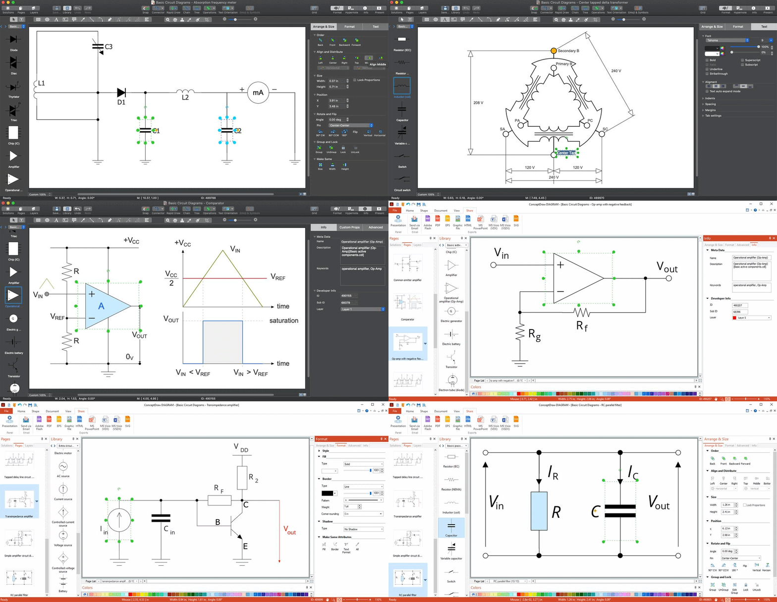
Inside
What I Need to Get Started
Both ConceptDraw DIAGRAM diagramming and drawing software and the Basic Circuit Diagrams solution can help creating the illustrations the technical documentation of an engineering projects you need. The Basic Circuit Diagrams solution can be found in the Industrial Engineering area of ConceptDraw STORE application that can be downloaded from this site. Make sure that both ConceptDraw DIAGRAM and ConceptDraw STORE applications are installed on your computer before you get started.
How to install
After ConceptDraw STORE and ConceptDraw DIAGRAM are downloaded and installed, you can install the Basic Circuit Diagrams solution from the ConceptDraw STORE.
Start Using
To make sure that you are doing it all right, use the pre-designed symbols from the stencil libraries from the solution to make your drawings look smart and professional. Also, the pre-made examples from this solution can be used as drafts so your own drawings can be based on them. Using the samples, you can always change their structures, colors and data.
