- Electric and Telecom Plans Free
- Fire and Emergency Plans Free
- Floor Plans Free
- Plant Layout Plans Free
- School and Training Plans Free
- Seating Plans Free
- Security and Access Plans Free
- Site Plans Free
- Sport Field Plans Free
- Business Process Diagrams Free
- Business Process Mapping Free
- Classic Business Process Modeling Free
- Cross-Functional Flowcharts Free
- Event-driven Process Chain Diagrams Free
- IDEF Business Process Diagrams Free
- Logistics Flow Charts Free
- Workflow Diagrams Free
- ConceptDraw Dashboard for Facebook Free
- Mind Map Exchange Free
- MindTweet Free
- Note Exchange Free
- Project Exchange Free
- Social Media Response Free
- Active Directory Diagrams Free
- AWS Architecture Diagrams Free
- Azure Architecture Free
- Cisco Network Diagrams Free
- Cisco Networking Free
- Cloud Computing Diagrams Free
- Computer Network Diagrams Free
- Google Cloud Platform Free
- Interactive Voice Response Diagrams Free
- Network Layout Floor Plans Free
- Network Security Diagrams Free
- Rack Diagrams Free
- Telecommunication Network Diagrams Free
- Vehicular Networking Free
- Wireless Networks Free
- Comparison Dashboard Free
- Composition Dashboard Free
- Correlation Dashboard Free
- Frequency Distribution Dashboard Free
- Meter Dashboard Free
- Spatial Dashboard Free
- Status Dashboard Free
- Time Series Dashboard Free
- Basic Circle-Spoke Diagrams Free
- Basic Circular Arrows Diagrams Free
- Basic Venn Diagrams Free
- Block Diagrams Free
- Concept Maps Free
- Family Tree Free
- Flowcharts Free
- Basic Area Charts Free
- Basic Bar Graphs Free
- Basic Divided Bar Diagrams Free
- Basic Histograms Free
- Basic Line Graphs Free
- Basic Picture Graphs Free
- Basic Pie Charts Free
- Basic Scatter Diagrams Free
- Aerospace and Transport Free
- Artwork Free
- Audio, Video, Media Free
- Business and Finance Free
- Computers and Communications Free
- Holiday Free
- Manufacturing and Maintenance Free
- Nature Free
- People Free
- Presentation Clipart Free
- Safety and Security Free
- Analog Electronics Free
- Audio and Video Connectors Free
- Basic Circuit Diagrams Free
- Chemical and Process Engineering Free
- Digital Electronics Free
- Electrical Engineering Free
- Electron Tube Circuits Free
- Electronic Block Diagrams Free
- Fault Tree Analysis Diagrams Free
- GHS Hazard Pictograms Free
- Home Automation and Wiring Free
- Mechanical Engineering Free
- One-line Diagrams Free
- Power Сircuits Free
- Specification and Description Language (SDL) Free
- Telecom and AV Circuits Free
- Transport Hazard Pictograms Free
- Data-driven Infographics Free
- Pictorial Infographics Free
- Spatial Infographics Free
- Typography Infographics Free
- Calendars Free
- Decision Making Free
- Enterprise Architecture Diagrams Free
- Fishbone Diagrams Free
- Organizational Charts Free
- Plan-Do-Check-Act (PDCA) Free
- Seven Management and Planning Tools Free
- SWOT and TOWS Matrix Diagrams Free
- Timeline Diagrams Free
- Australia Map Free
- Continent Maps Free
- Directional Maps Free
- Germany Map Free
- Metro Map Free
- UK Map Free
- USA Maps Free
- Customer Journey Mapping Free
- Marketing Diagrams Free
- Matrices Free
- Pyramid Diagrams Free
- Sales Dashboard Free
- Sales Flowcharts Free
- Target and Circular Diagrams Free
- Cash Flow Reports Free
- Current Activities Reports Free
- Custom Excel Report Free
- Knowledge Reports Free
- MINDMAP Reports Free
- Overview Reports Free
- PM Agile Free
- PM Dashboards Free
- PM Docs Free
- PM Easy Free
- PM Meetings Free
- PM Planning Free
- PM Presentations Free
- PM Response Free
- Resource Usage Reports Free
- Visual Reports Free
- House of Quality Free
- Quality Mind Map Free
- Total Quality Management TQM Diagrams Free
- Value Stream Mapping Free
- Astronomy Free
- Biology Free
- Chemistry Free
- Language Learning Free
- Mathematics Free
- Physics Free
- Piano Sheet Music Free
- Android User Interface Free
- Class Hierarchy Tree Free
- Data Flow Diagrams (DFD) Free
- DOM Tree Free
- Entity-Relationship Diagram (ERD) Free
- EXPRESS-G data Modeling Diagram Free
- IDEF0 Diagrams Free
- iPhone User Interface Free
- Jackson Structured Programming (JSP) Diagrams Free
- macOS User Interface Free
- Object-Role Modeling (ORM) Diagrams Free
- Rapid UML Free
- SYSML Free
- Website Wireframe Free
- Windows 10 User Interface Free
Home Automation and Wiring
Nowadays, we are living in the world of automation. We are surrounded everywhere by automation systems, electronic devices of wired and wireless working principles. Most of the systems are automated in our homes, offices, recreation areas, etc. The automation systems make our life more comfortable and simple, most of our daily actions become easier. The machines simplify human efforts, they are convenient and energy-efficient. Moreover, day by day the automation processes are improved and become more advanced. The main advantage is that many systems are controlled and managed remotely with automatic devices and modern technologies. The centralized remote control of heating, lighting, air conditioning, security systems, home appliances, and other home automation equipment is possible today.
Home automation including smart home systems is implemented based on wired or wireless equipment. The diversity of the used equipment impresses. It includes common electrical equipment and wires and wireless devices, sensors of different kinds, controlling and scheduling devices, video surveillance equipment, and more. The sensors contain special sensing elements and are used to detect motion, changes in lighting, temperature, humidity, pressure, etc. The received data are sent to the main controlling devices (computers, laptops, smartphones, tablets, etc.) with special control applications installed. The scheduling devices help in heat and energy saving. Video surveillance allows implementing continuous monitoring.
Among the final controlling devices and mechanisms are switches, relays, motors. They control the home equipment and remote managing these devices is also possible. In this way, communication plays an important role in home automation making possible remote access to the devices and operations. And certainly, the installation of any equipment requires enforcing building codes and safety standards.
Smart home systems commonly include modern smart devices: smart light switches, smart outlets, smart thermostats, smart doorbells, smart smoke alarms, in-wall transmitters, surge protection equipment, junction boxes, etc. Smart wiring and structured wiring systems are used in the realization of smart home systems. They suppose the use of a series of panels to organize different types of wires and cables and provide reliable automation and internet coverage in your home.
As for the choice of wired or wireless technologies, both have their own pros and cons. The final decision is taken based on many attendant factors and often they are combined. A great value has it is a new home or building for the renovation. Wired systems are reliable, but are less convenient and easy to operate compared to wireless ones. It is easier to mount a wired system in a new building. Wireless systems are less demanding, easier for installation, and perfectly suit for installation when repairing or remodeling a building. However, a large number of wireless devices connected to the network can cause slowing, weakening a signal, or dropping connection.
Building, repairing, wiring, and automating a home or other building has never been an easy task. But planning and modern design software ConceptDraw DIAGRAM and Home Automation and Wiring solution are able to simplify this process. Develop modern solutions for home automation, construct electrical plans and electronic wiring diagrams, design electrical diagram for a smart home system, implement innovations and modern technologies, and describe wiring simply and professionally in ConceptDraw DIAGRAM. Home Automation and Wiring solution includes a lot of practical examples of home automation and wiring, and a large collection of vector stencils of home automation equipment, alarm and security equipment, home appliances, electrical symbols, light switches, plugs, sockets, wiring diagram symbols, and more. Add descriptions and a legend to help understand the basic electrical terms and used symbols. Home Automation and Wiring solution is the best way to make your home smart still the planning stage and construction of your home electrical schematic.
-
What I need to get started -
Solution Requirements - This solution requires the following products to be installed:
ConceptDraw DIAGRAM v18 - This solution requires the following products to be installed:
-
Helpdesk
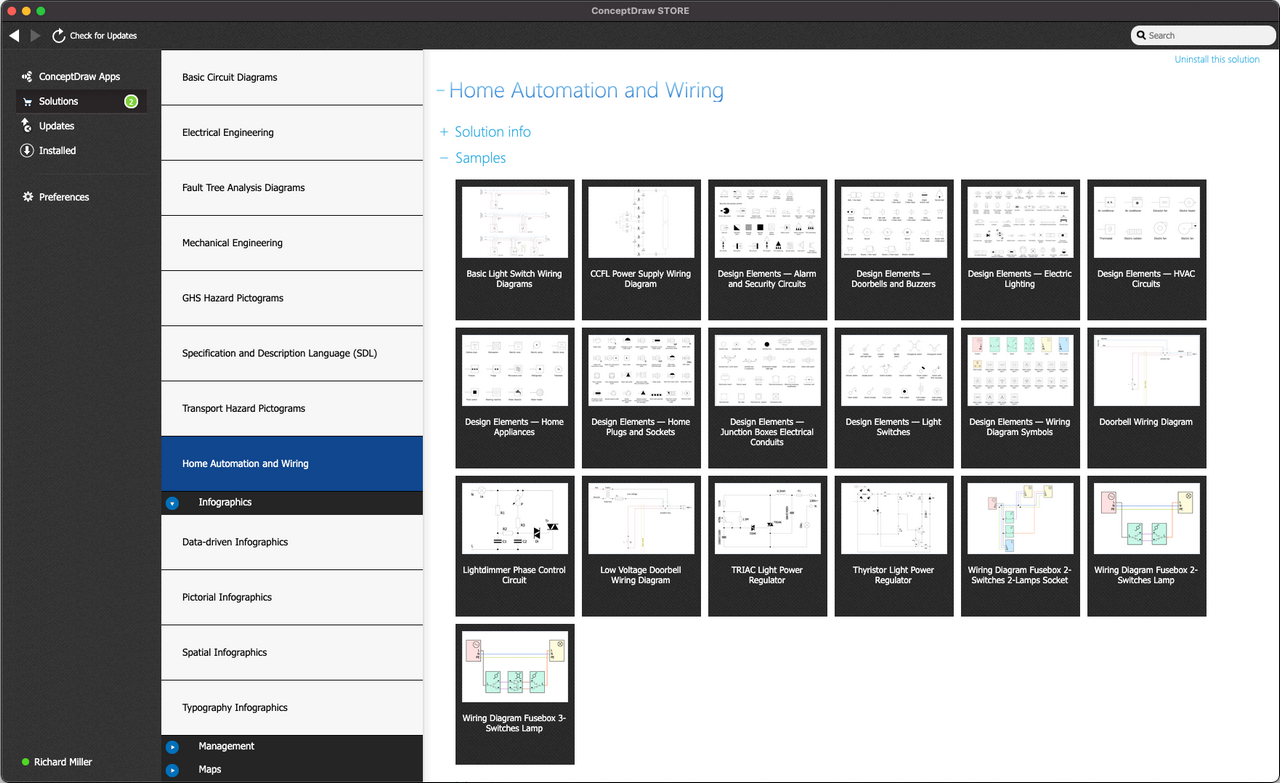
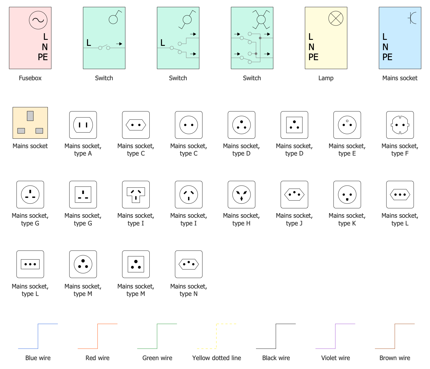
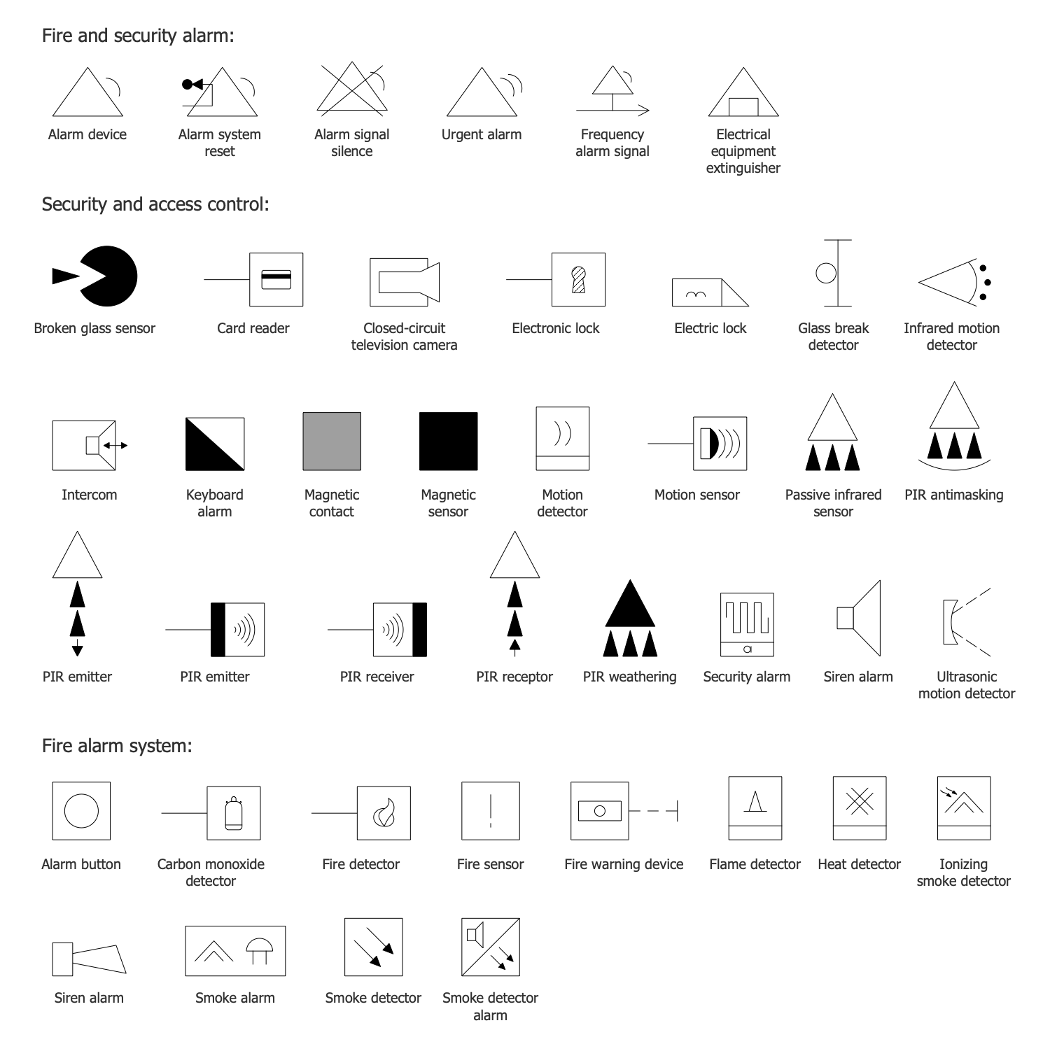
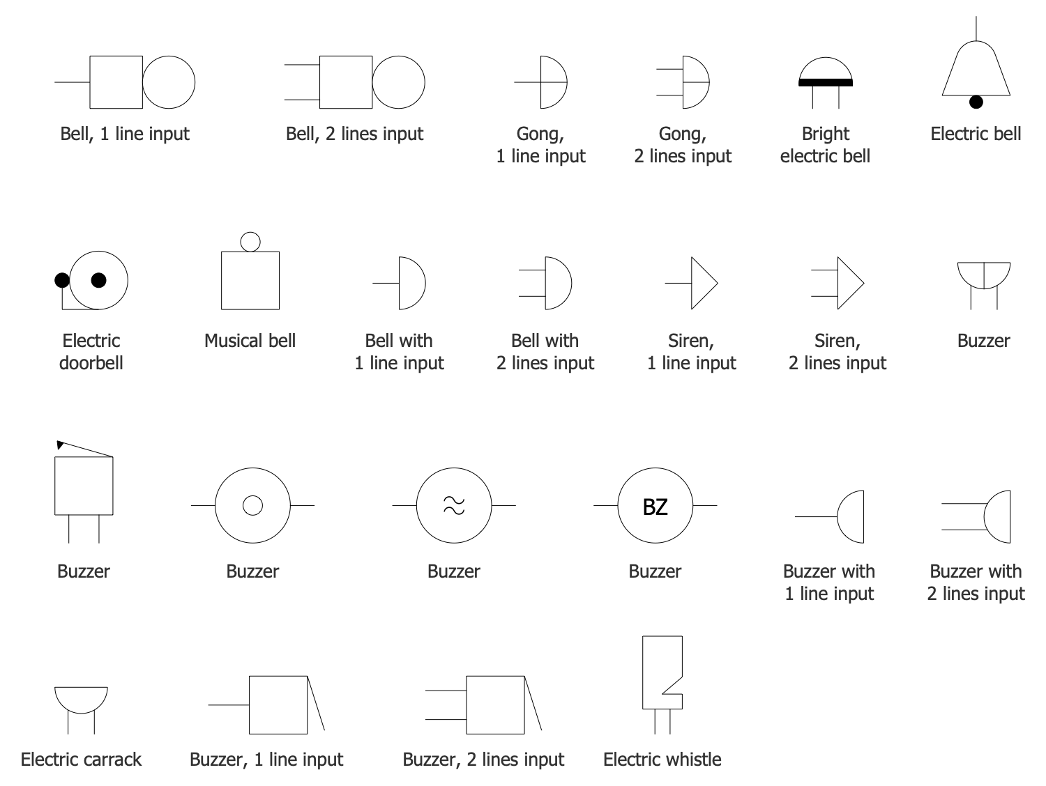
ConceptDraw Home Automation and Wiring solution includes 9 stencil libraries containing 247 industry-standard images and 10 examples.
Design Elements — Wiring Diagram Symbols
Design Elements — Alarm and Security Circuits
Design Elements — Doorbells and Buzzers
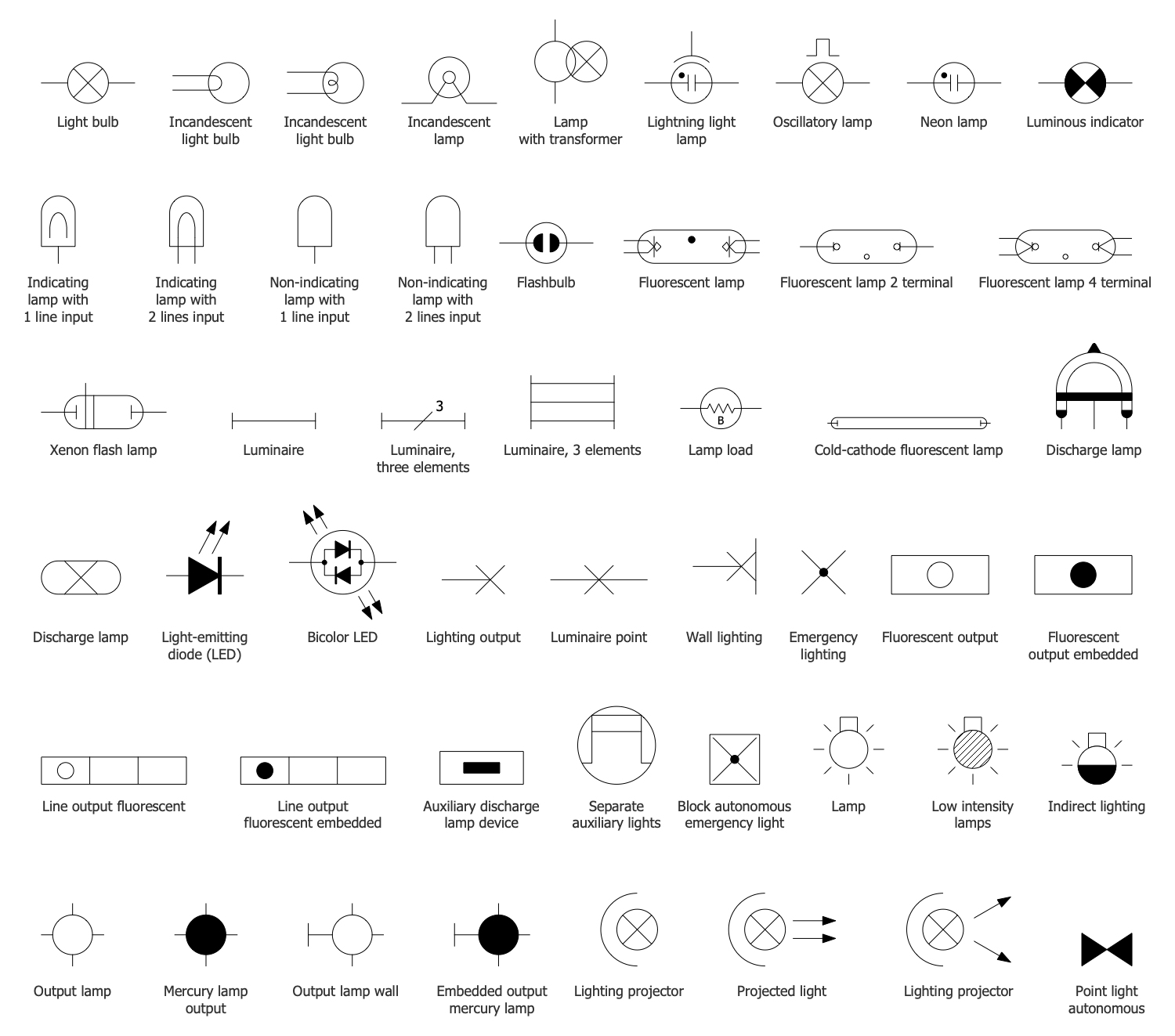
Design Elements — Electric Lighting
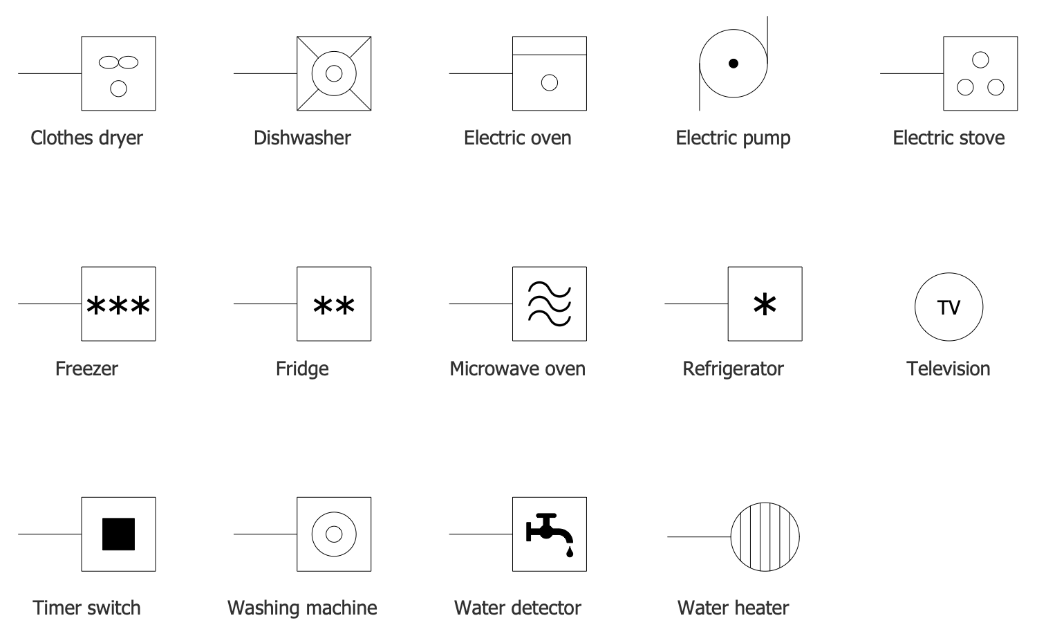
Design Elements — Home Appliances
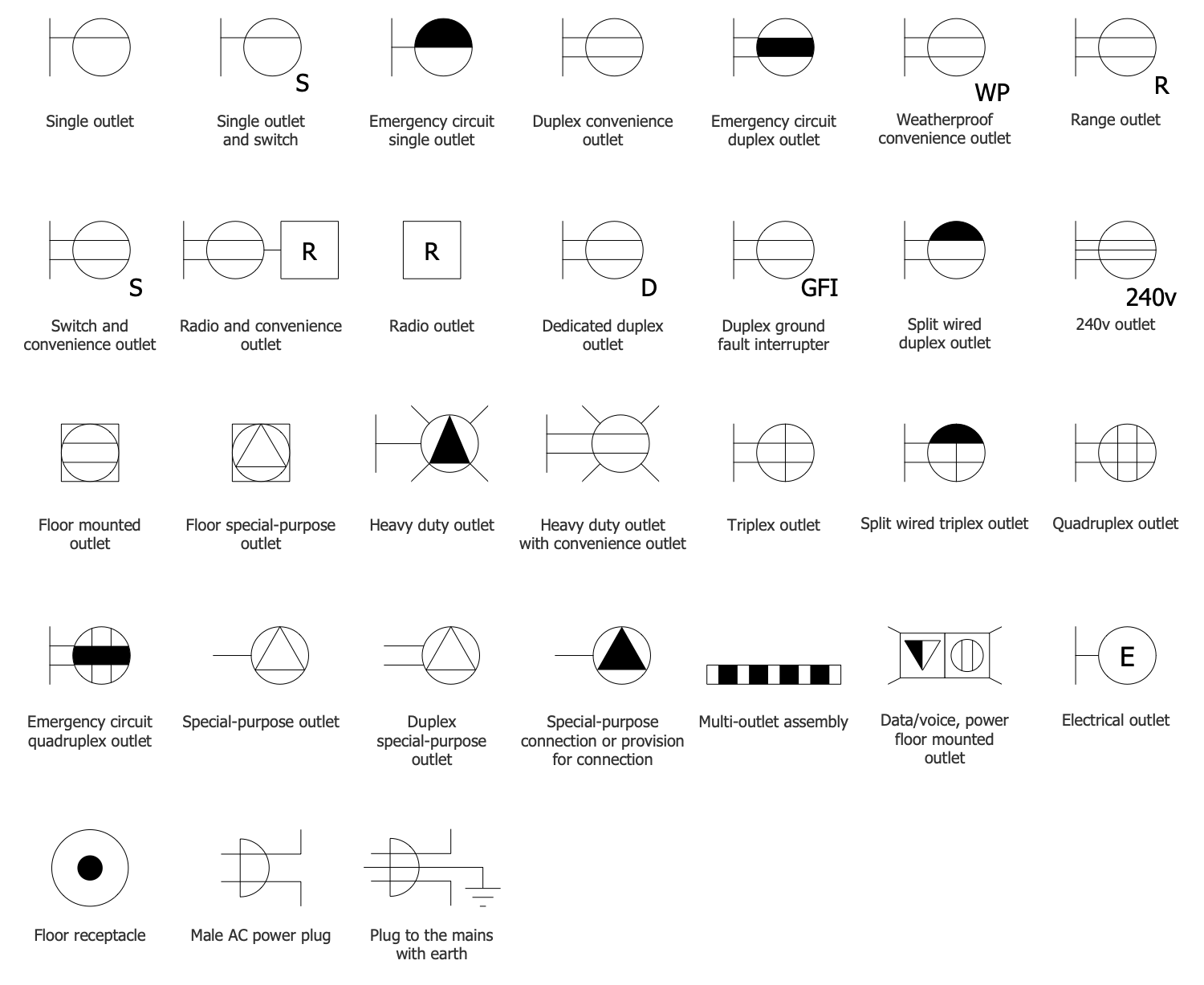
Design Elements — Home Plugs and Sockets
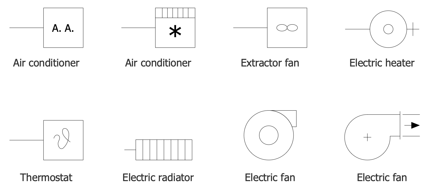
Design Elements — HVAC Circuits
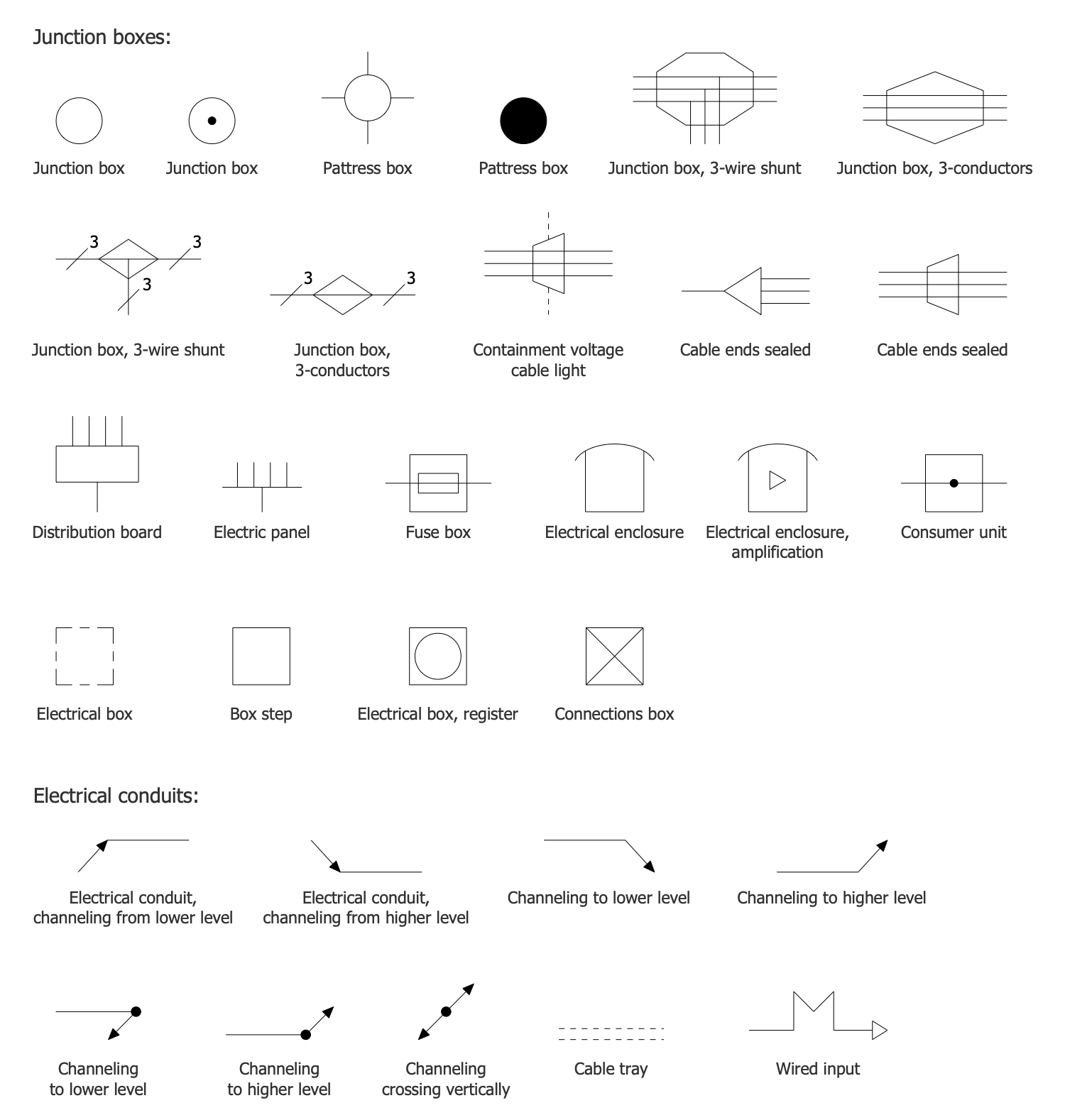
Design Elements — Junction Boxes Electrical Conduits
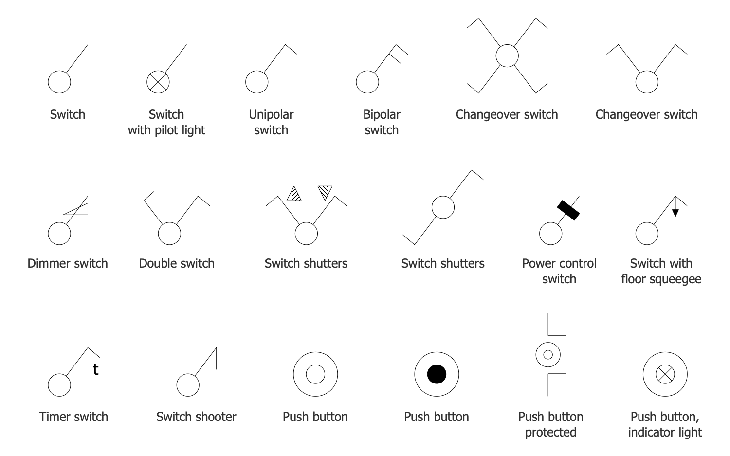
Design Elements — Light Switches
Examples
There are a few samples that you see on this page which were created in the ConceptDraw DIAGRAM application by using the Wiring solution. Some of the solution's capabilities as well as the professional results which you can achieve are all demonstrated here on this page.
All source documents are vector graphic documents which are always available for modifying, reviewing and/or converting to many different formats, such as MS PowerPoint, PDF file, MS Visio, and many other graphic ones from the ConceptDraw Solution Park or ConceptDraw STORE. The Wiring solution is available to all ConceptDraw DIAGRAM users to install and use it for working in diagramming and drawing.
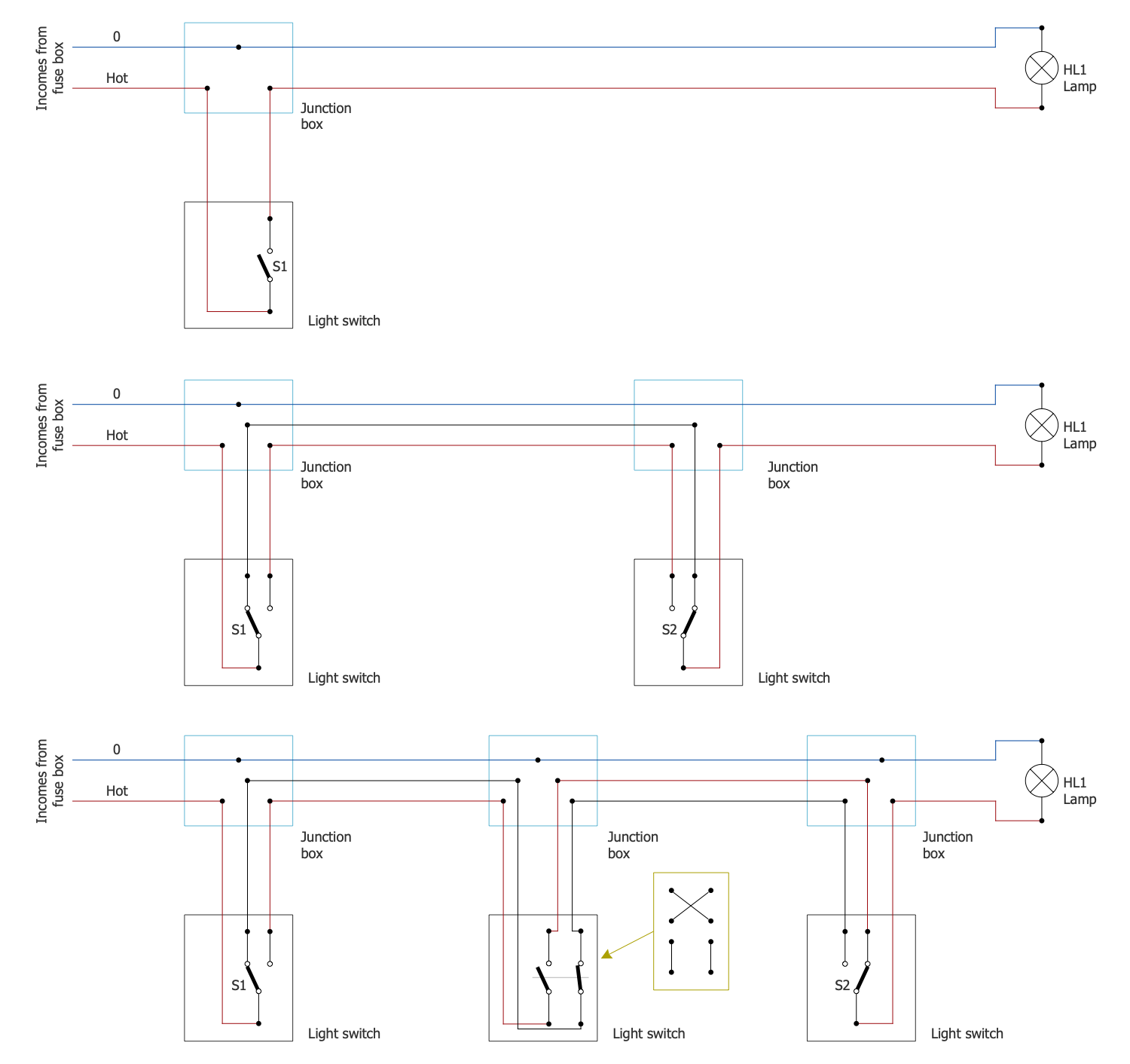
Example 1: Basic Light Switch Wiring Diagrams
This diagram was created in ConceptDraw DIAGRAM using a combination of libraries from the Home Automation and Wiring Solution. An experienced user spent 15 minutes creating this sample.
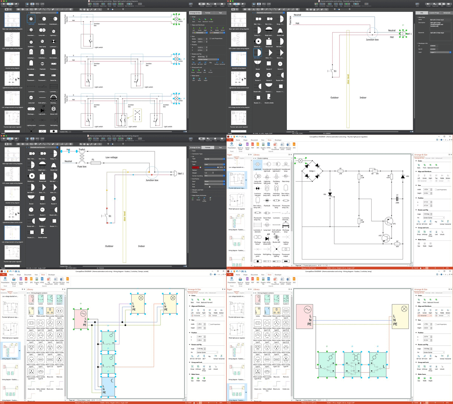
This sample shows a set of basic wiring diagrams of the light switches. You can see the schematics of the correct use of junction boxes and switches. The junction boxes help to avoid problems with many wires. Because sometimes the superfluous wires are connected in a small outlet box that makes a mess and inconvenience. As for the switches, the use of two or more electrical switches is widespread. Numerous switches allow controlling an electrical load and lighting from more than one location. The installation of the two-way, three-way or four-way switches allows you to control a light from the corresponding number of locations. These can be opposite sides of a large room, a long hallway, the top and bottom of a stairway, etc. These schematics are basic and you can easily modify them according to your needs and requirements. At the use of parts with metal cover, add a ground wire or use the knots with dielectric cover.
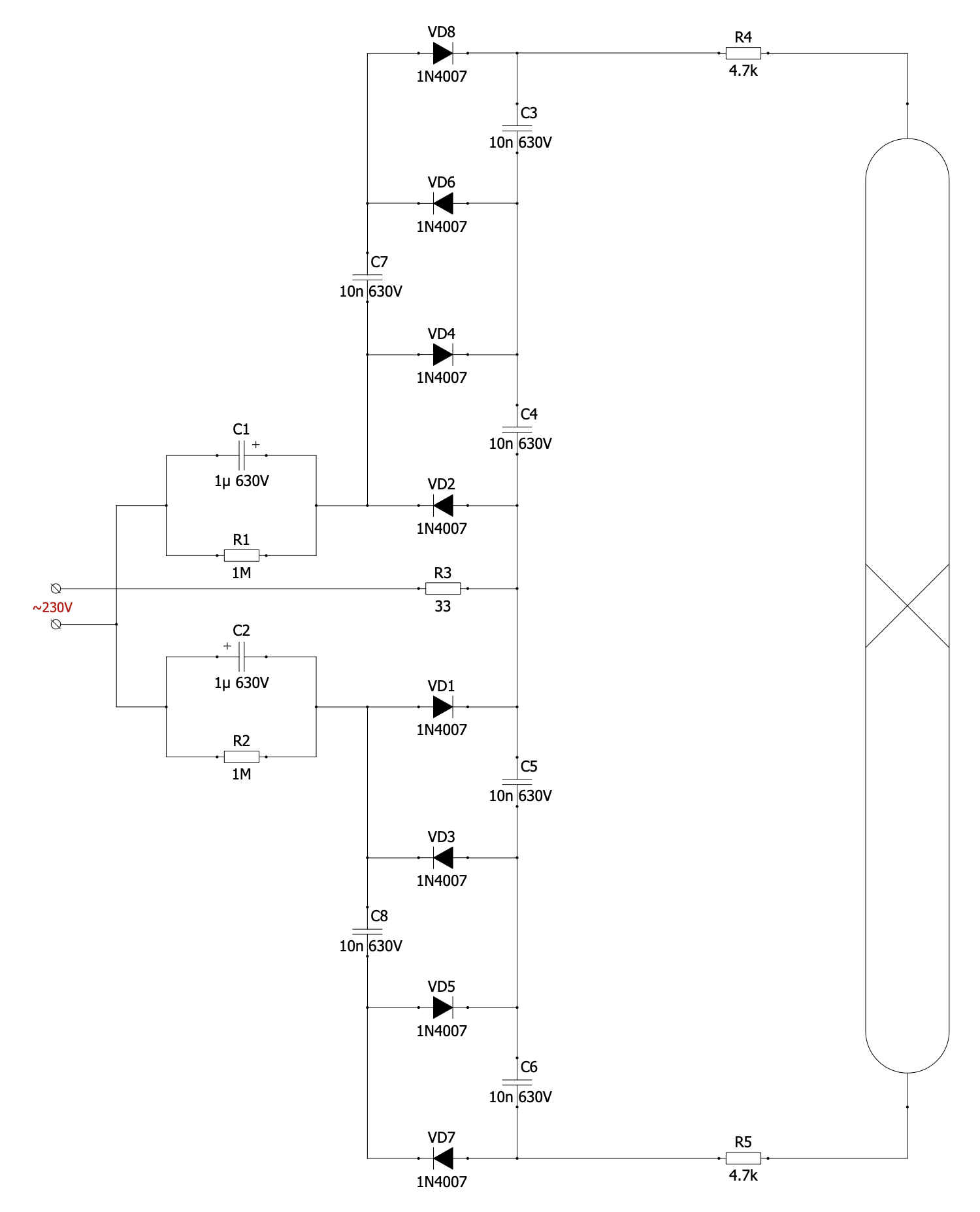
Example 2: CCFL Power Supply Wiring Diagram
This diagram was created in ConceptDraw DIAGRAM using a combination of libraries from the Home Automation and Wiring Solution. An experienced user spent 10 minutes creating this sample.
This Wiring diagram shows the power supply circuit with CCFL. The cold-cathode fluorescent lamps (CCFLs) are the components of the gas-discharge lamps, neon lamps, cold-cathode lamps, vacuum and discharge tubes, cold-cathode switching tubes, thyratrons, krytrons, cold-cathode displays or Nixie tubes, etc. A cold cathode isn't heated previously and isn't heated electrically by a filament. But it doesn't mean that cold cathode operates at a low temperature. Typically, similar to the hot cathode, it is heated to the operating temperature during work. The current passing from the cathode into the gas is used to heat it. The cold-cathode fluorescent lamps emit more electrons than the thermionic emission offers. However, they use higher voltages than hot-cathode lamps. The cold-cathode lamps using the CCFLs contain a discharge in mercury vapor that develops ultraviolet light and causes the emission of visible light. These lamps are used for backlighting the LCDs.
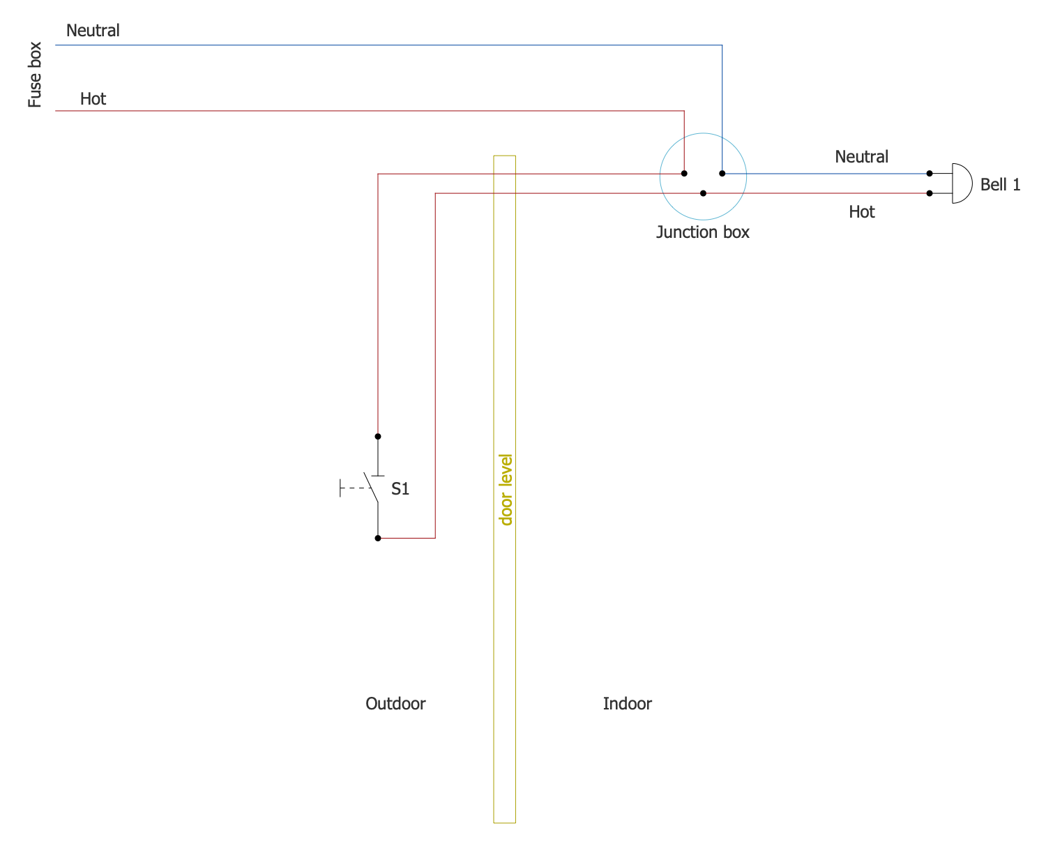
Example 3: Doorbell Wiring Diagram
This diagram was created in ConceptDraw DIAGRAM using a combination of libraries from the Home Automation and Wiring Solution. An experienced user spent 10 minutes creating this sample.
This Wiring diagram shows a typical doorbell circuit. Being a type of signaling device, a doorbell is installed outside the apartment, house, or another premise. Typically, it is placed next to the entrance door. Being activated, in common by a simple press, it provides the bell ring inside the corresponding premise. A doorbell includes three main parts: the push button, the chime, and the transformer. These parts are connected with wires in a doorbell of a wired-type system. This diagram is a simple guide on how to wire a doorbell. Hot and neutral wires are differentiated by colors: red and blue. The mechanism of work is quite simple. When the doorbell button is pressed, the doorbell circuit is closed and the doorbell rings. But the doorbell cannot be connected directly to the electrical system and requires a lower voltage. The transformer is used to reduce the voltage from 120 or 240 volts to the value at which the doorbell operates (10-24 volts). Usually the doorbell transformer is connected to an electrical junction box.
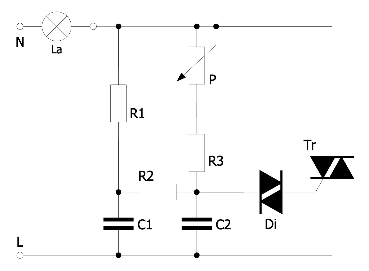
Example 4: Lightdimmer Phase Control Circuit
This diagram was created in ConceptDraw DIAGRAM using a combination of libraries from the Home Automation and Wiring Solution. An experienced user spent 10 minutes creating this sample.
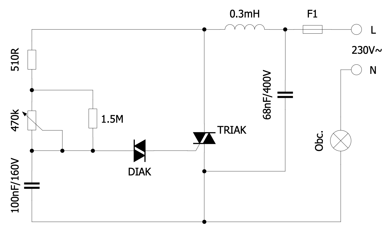
This sample shows a simplified schematic of a phase control circuit used for dimming a light. The dimming process is generally directed at the control of the amount of electrical power supplied to a light source and changing brightness. The different types of dimming are applied. The universal dimmers are most widespread, they recognize the load characteristics and adjust the control method accordingly. More complex circuits are controlled by the phase control dimmers. At the same time, because the discharge is destroyed at low voltage, fluorescent lamps and gas-discharge lamps cannot be darkened. The use of potentiometer P in this diagram allows changing the brightness of the incandescent lamp La. The lamp is controlled by a triac Tr and is lit via diac Di. R1 and C1 reduce the hysteresis, and R2 and C2 form two phase shifts. AC voltage has a delay. The lower the resistance of the potentiometer P is, the earlier Di and Tr will light up and the lamp will light brighter. A collection of electrical symbols included to the libraries of Home Automation and Wiring solution is a perfect assistant in designing home automation diagrams and plans.
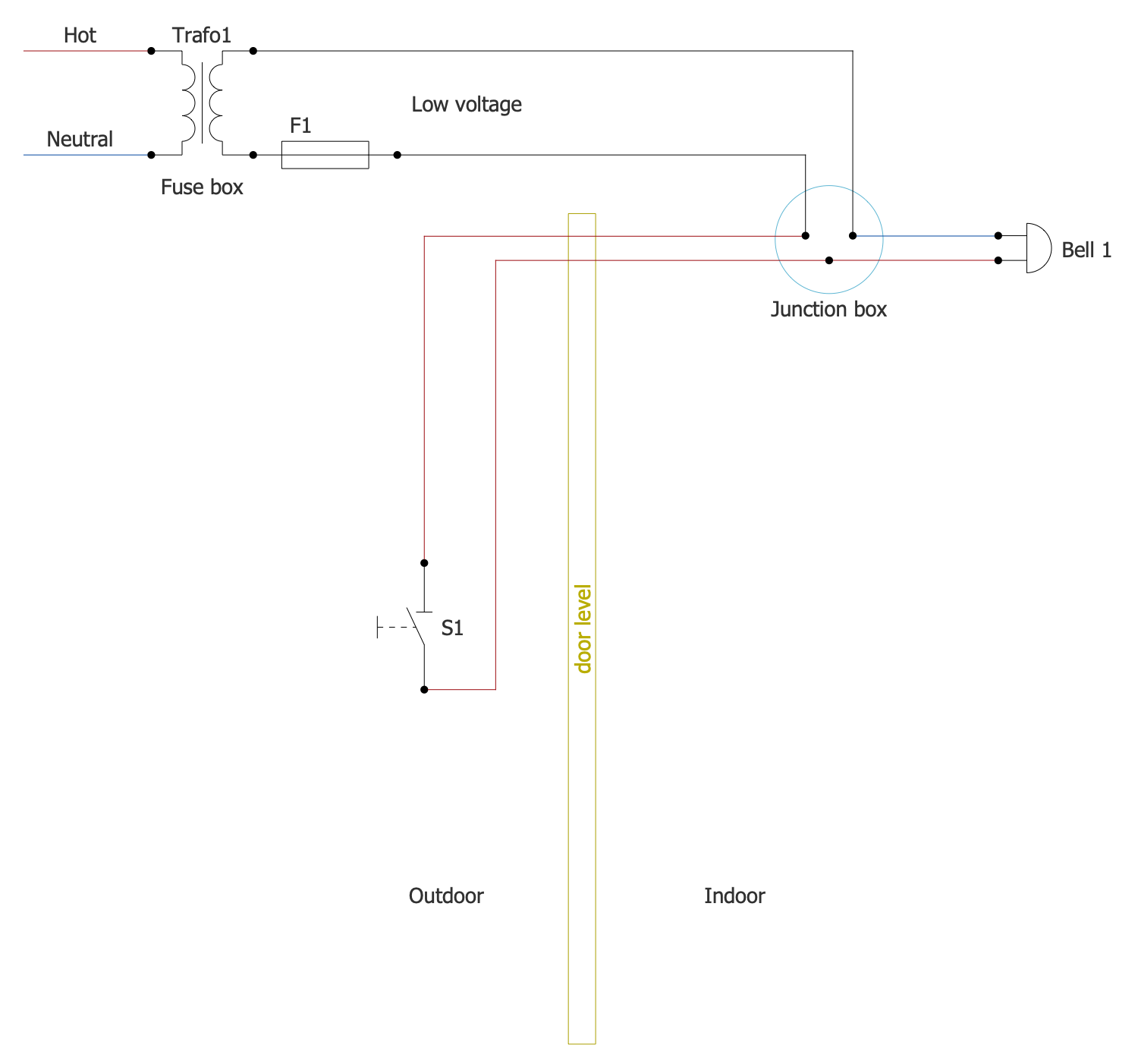
Example 5: Low Voltage Doorbell Wiring Diagram
This diagram was created in ConceptDraw DIAGRAM using a combination of libraries from the Home Automation and Wiring Solution. An experienced user spent 10 minutes creating this sample.
This sample shows a wiring diagram for the low voltage doorbell. The circuit includes a fuse box and junction box. The fuses are devices installed in electrical systems to protect them against potential dangers. Among the primary dangers are power surges or excessive temperatures. And a fuse box is a metal container for the fuses. Several fuses for the electrical system of a single house or apartment are placed in a fuse box. Typically, fuse boxes are sized for 6-12 fuses. An electrical junction box or jbox is a housing that contains electrical connections. It prevents accidental electric shock and protects electrical connections from the weather elements. It is surface mounted or recessed into a wall, ceiling, floor, etc. The low voltage doorbell circuit necessarily includes a transformer to step down the voltage from a high AC power to a lower one. This circuit uses two wires, hot and neutral, colored differently: red and blue.
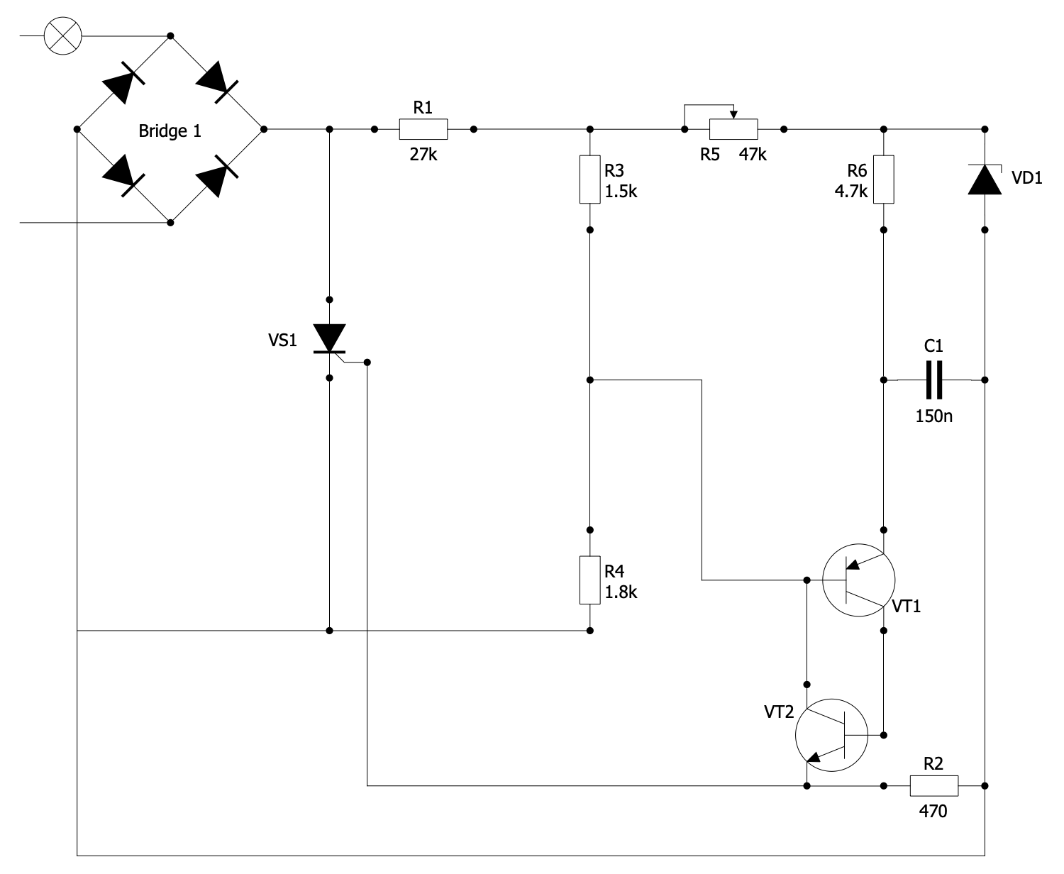
Example 6: Thyristor Light Power Regulator
This diagram was created in ConceptDraw DIAGRAM using a combination of libraries from the Home Automation and Wiring Solution. An experienced user spent 15 minutes creating this sample.
This diagram sample shows the electrical schematic of a light power regulator using a thyristor. The thyristor light power regulator allows you to change the power supplied to the load due to the delay in turning on the thyristor in the half-cycle of the alternating current. The thyristor is a key component of this circuit. When a signal appears on the control electrode, the thyristor opens. The longer the switch-on delay is, the less power is supplied to the load. Transistors VT1 and VT2 operate in the key mode. When the voltage on the capacitor C1 is equal to the voltage at the point between the resistors R3 and R4, the transistors open. They send a signal to the control electrode of the thyristor VS1. The capacitor is discharged and the thyristor opens until the next half cycle. This circuit is quite simple and starts working immediately after switching on. It is mainly applied to power control of AC loads, universal collector motors, incandescent lamps. However, the use of 5 power elements that heat up during operation is its key disadvantage compared to triac regulators using one power element.
Example 7: TRIAC Light Power Regulator
This diagram was created in ConceptDraw DIAGRAM using a combination of libraries from the Home Automation and Wiring Solution. An experienced user spent 10 minutes creating this sample.
This sample shows a circuit of a triac light power regulator. Triacs are used in AC circuits to conduct current. They act as regulator keys used to create circuits. Triacs are semiconductor elements related to thyristors. Typically, a triac includes three outputs: one control (gateway G) and two power outputs (anodes A1 and A2), which, when triggered, conduct current in two directions. The triac is turned on by the gate current and, accordingly, turned off in the absence of current. Triacs are often used as bi-directional connectors, relays, or power regulators. They work in both directions of polarization and behave like thyristors in the positive part. Triac switching occurs regardless of polarization. Triacs are widely used in electronics. They are used in motor speed controllers, electric fans, home appliances, dimmers and more. Use the drawing tools in ConceptDraw DIAGRAM and Home Automation and Wiring to efficiently create circuits with all the elements you need, including triacs, diacs and more.
Example 8: Wiring Diagram Fusebox 2-Switches 2-Lamps Socket
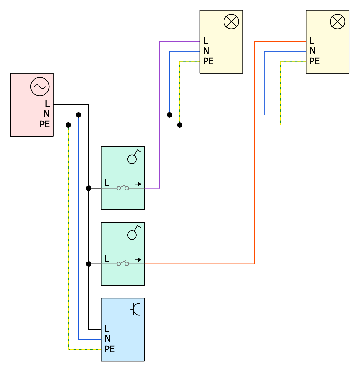
This diagram was created in ConceptDraw DIAGRAM using a combination of libraries from the Home Automation and Wiring Solution. An experienced user spent 5 minutes creating this sample.
This electric diagram includes a fusebox, two switches, two lamps, and a socket. The lamps in this schematic are switched on independently of each other. The lights located in different rooms have their own different connection schemes and differ in the number of switches. Switches and sockets are used to control the lights. Typically, the lighting fixtures on walls and ceiling do not have plugs and are switched using switches mounted on the wall. In addition, the lights of different and the same types of connection are also often combined in one room. In any case, they are connected as parallel consumers. The switch is connected to the lamp by a special conductor called a switched conductor. Some devices include an internal circuit allowing them to work for a certain time even after switching off. The bright colors are applied in Wiring diagrams for a visual effect and to highlight important points. Use the pre-made wiring diagram symbols from the libraries of Home Automation and Wiring solution to construct efficiently your own Wiring diagrams.
Example 9: Wiring Diagram Fusebox 2-Switches Lamp
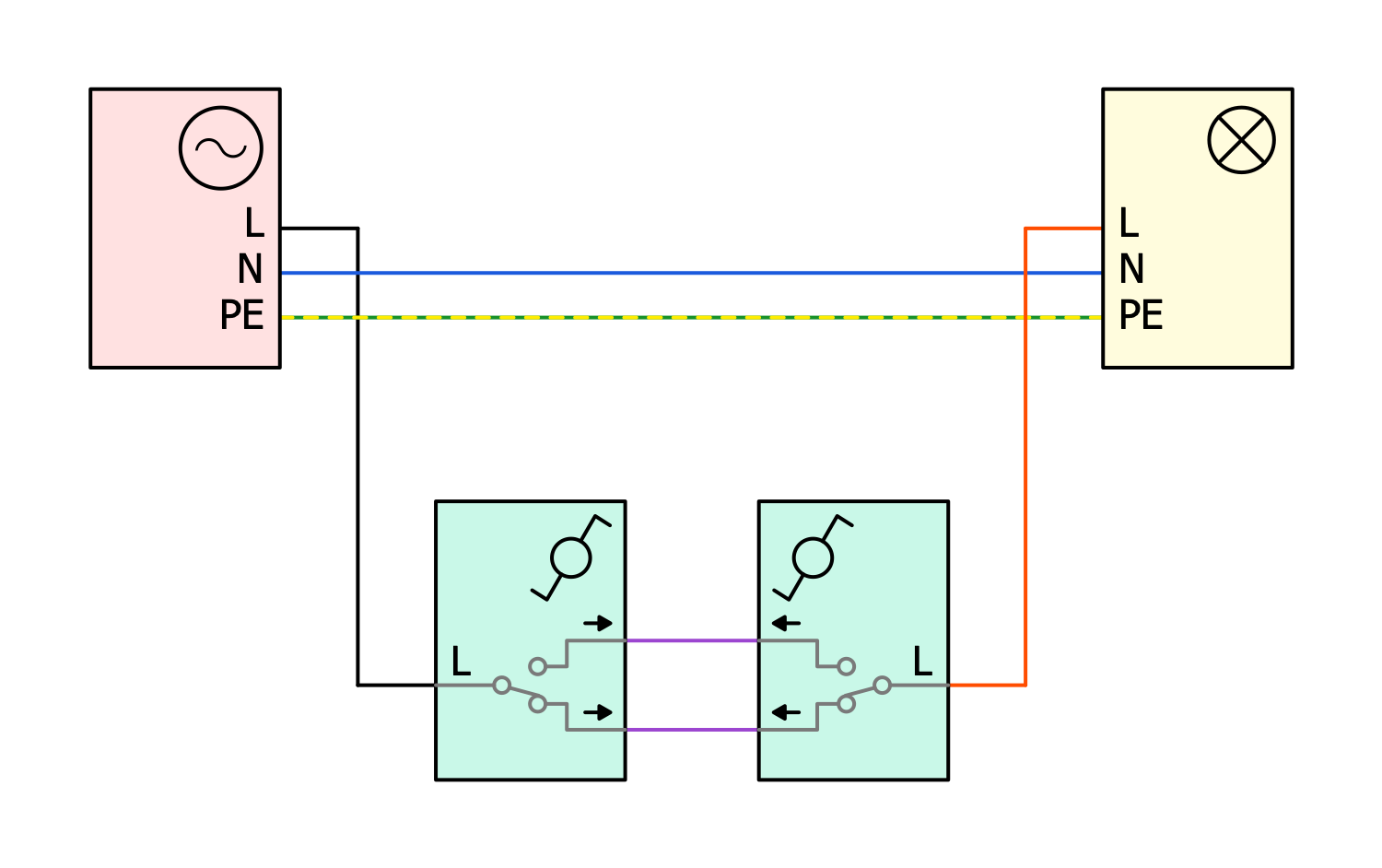
This diagram was created in ConceptDraw DIAGRAM using a combination of libraries from the Home Automation and Wiring Solution. An experienced user spent 5 minutes creating this sample.
This electrical wiring diagram shows the connection of a lamp. A fuse box is used to protect the buildings and premises from overloads and their consequences. The electricity is supplied to consumers from the fuse box. Each individual circuit in the fuse box is powered by three contacts: neutral conductor (N), phase (L), and protection conductor (PE). At the same time, the protection conductor is never interrupted and is a part of the protective mechanism. A voltage exists between the neutral conductor and the phase. This schematic includes one lamp, a fusebox, and two switches. The switches are interconnected by two conductors and are used to switch on the lamp. The conductor between the switch and the lamp is a switched conductor. One of the conductors is connected to the phase. If it is also connected to the lamp via another switch, the lamp lights up.
Example 10: Wiring Diagram Fusebox 3-Switches Lamp
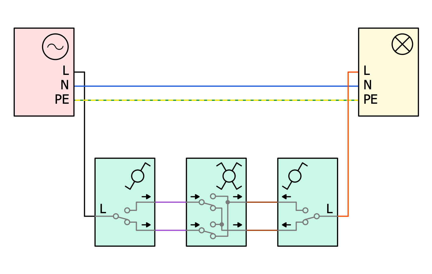
This diagram was created in ConceptDraw DIAGRAM using a combination of libraries from the Home Automation and Wiring Solution. An experienced user spent 5 minutes creating this sample.
This diagram shows a circuit that includes a lamp and three switches. The switches are cross-linked. The circuit includes two single switches and one double. Two switches are reconnected to two corresponding switches. A two-position switch connects two other switches in parallel. Two switches conduct phase current. The lamp lights up when the first switch is connected to the second in phase, and the third switch to the fourth in antiphase. The switches are toggled from bottom to top and up to down. This is why they overlap. ConceptDraw DIAGRAM software and home automation and wiring solution enable you to create a wide variety of wiring diagrams, electrical wiring diagrams, home appliance wiring plans and more. Use it to create circuits with one, two or more switches, one or more lamps, and a fuse box, sockets or without them and more diagrams.
Inside
What I Need to Get Started
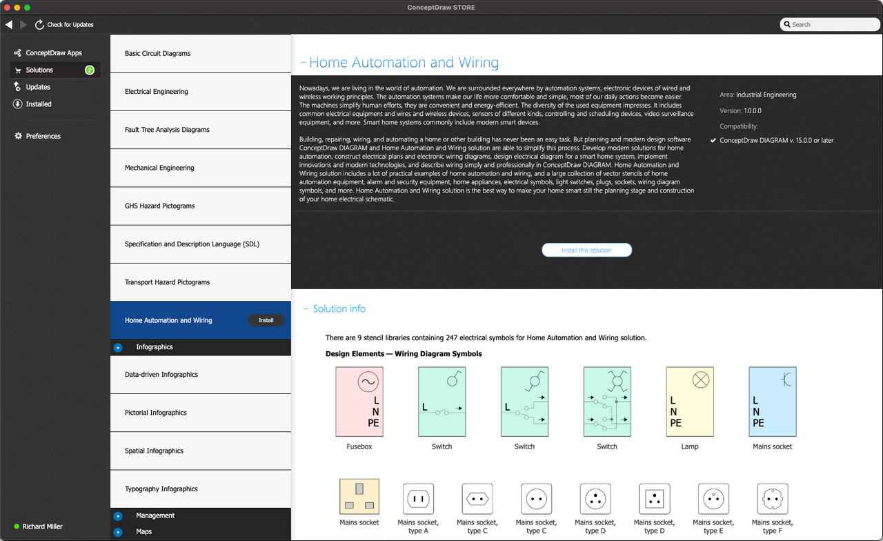
Both ConceptDraw DIAGRAM diagramming and drawing software and the Home Automation and Wiring solution can help creating the illustrations the technical documentation of an engineering projects you need. The Home Automation and Wiring solution can be found in the Industrial Engineering area of ConceptDraw STORE application that can be downloaded from this site. Make sure that both ConceptDraw DIAGRAM and ConceptDraw STORE applications are installed on your computer before you get started.
How to install
After ConceptDraw STORE and ConceptDraw DIAGRAM are downloaded and installed, you can install the Home Automation and Wiring solution from the ConceptDraw STORE.
Start Using
To make sure that you are doing it all right, use the pre-designed symbols from the stencil libraries from the solution to make your drawings look smart and professional. Also, the pre-made examples from this solution can be used as drafts so your own drawings can be based on them. Using the samples, you can always change their structures, colors and data.
