- Electric and Telecom Plans Free
- Fire and Emergency Plans Free
- Floor Plans Free
- Plant Layout Plans Free
- School and Training Plans Free
- Seating Plans Free
- Security and Access Plans Free
- Site Plans Free
- Sport Field Plans Free
- Business Process Diagrams Free
- Business Process Mapping Free
- Classic Business Process Modeling Free
- Cross-Functional Flowcharts Free
- Event-driven Process Chain Diagrams Free
- IDEF Business Process Diagrams Free
- Logistics Flow Charts Free
- Workflow Diagrams Free
- ConceptDraw Dashboard for Facebook Free
- Mind Map Exchange Free
- MindTweet Free
- Note Exchange Free
- Project Exchange Free
- Social Media Response Free
- Active Directory Diagrams Free
- AWS Architecture Diagrams Free
- Azure Architecture Free
- Cisco Network Diagrams Free
- Cisco Networking Free
- Cloud Computing Diagrams Free
- Computer Network Diagrams Free
- Google Cloud Platform Free
- Interactive Voice Response Diagrams Free
- Network Layout Floor Plans Free
- Network Security Diagrams Free
- Rack Diagrams Free
- Telecommunication Network Diagrams Free
- Vehicular Networking Free
- Wireless Networks Free
- Comparison Dashboard Free
- Composition Dashboard Free
- Correlation Dashboard Free
- Frequency Distribution Dashboard Free
- Meter Dashboard Free
- Spatial Dashboard Free
- Status Dashboard Free
- Time Series Dashboard Free
- Basic Circle-Spoke Diagrams Free
- Basic Circular Arrows Diagrams Free
- Basic Venn Diagrams Free
- Block Diagrams Free
- Concept Maps Free
- Family Tree Free
- Flowcharts Free
- Basic Area Charts Free
- Basic Bar Graphs Free
- Basic Divided Bar Diagrams Free
- Basic Histograms Free
- Basic Line Graphs Free
- Basic Picture Graphs Free
- Basic Pie Charts Free
- Basic Scatter Diagrams Free
- Aerospace and Transport Free
- Artwork Free
- Audio, Video, Media Free
- Business and Finance Free
- Computers and Communications Free
- Holiday Free
- Manufacturing and Maintenance Free
- Nature Free
- People Free
- Presentation Clipart Free
- Safety and Security Free
- Analog Electronics Free
- Audio and Video Connectors Free
- Basic Circuit Diagrams Free
- Chemical and Process Engineering Free
- Digital Electronics Free
- Electrical Engineering Free
- Electron Tube Circuits Free
- Electronic Block Diagrams Free
- Fault Tree Analysis Diagrams Free
- GHS Hazard Pictograms Free
- Home Automation and Wiring Free
- Mechanical Engineering Free
- One-line Diagrams Free
- Power Сircuits Free
- Specification and Description Language (SDL) Free
- Telecom and AV Circuits Free
- Transport Hazard Pictograms Free
- Data-driven Infographics Free
- Pictorial Infographics Free
- Spatial Infographics Free
- Typography Infographics Free
- Calendars Free
- Decision Making Free
- Enterprise Architecture Diagrams Free
- Fishbone Diagrams Free
- Organizational Charts Free
- Plan-Do-Check-Act (PDCA) Free
- Seven Management and Planning Tools Free
- SWOT and TOWS Matrix Diagrams Free
- Timeline Diagrams Free
- Australia Map Free
- Continent Maps Free
- Directional Maps Free
- Germany Map Free
- Metro Map Free
- UK Map Free
- USA Maps Free
- Customer Journey Mapping Free
- Marketing Diagrams Free
- Matrices Free
- Pyramid Diagrams Free
- Sales Dashboard Free
- Sales Flowcharts Free
- Target and Circular Diagrams Free
- Cash Flow Reports Free
- Current Activities Reports Free
- Custom Excel Report Free
- Knowledge Reports Free
- MINDMAP Reports Free
- Overview Reports Free
- PM Agile Free
- PM Dashboards Free
- PM Docs Free
- PM Easy Free
- PM Meetings Free
- PM Planning Free
- PM Presentations Free
- PM Response Free
- Resource Usage Reports Free
- Visual Reports Free
- House of Quality Free
- Quality Mind Map Free
- Total Quality Management TQM Diagrams Free
- Value Stream Mapping Free
- Astronomy Free
- Biology Free
- Chemistry Free
- Language Learning Free
- Mathematics Free
- Physics Free
- Piano Sheet Music Free
- Android User Interface Free
- Class Hierarchy Tree Free
- Data Flow Diagrams (DFD) Free
- DOM Tree Free
- Entity-Relationship Diagram (ERD) Free
- EXPRESS-G data Modeling Diagram Free
- IDEF0 Diagrams Free
- iPhone User Interface Free
- Jackson Structured Programming (JSP) Diagrams Free
- macOS User Interface Free
- Object-Role Modeling (ORM) Diagrams Free
- Rapid UML Free
- SYSML Free
- Website Wireframe Free
- Windows 10 User Interface Free
Telecom and AV Circuits
Fast and efficient electronic transmission of information over distances, known as telecommunications, is now a reality. Its implementation and development is realized through using the newest technologies and modern equipment. Telecommunications uses networks as channels to transmit information of different kinds: images, text, audio, voice, video, etc. The telecom network includes various telecommunications equipment, terminals for accessing the network, interconnected computers for processing information from each other, and special software for managing the transmission of messages over the network. The architecture of a telecommunications network determines its capabilities and performance.
There are several ways to implement telecommunication channels depending on the communication media used, classified as managed media, wireless media, analog and digital communications. Each one has its own characteristics like channel capacity, bandwidth, transmission speed, and correspondingly each of the listed ways suits different purposes. In controlled environments (coaxial cable, twisted pair, fiber optic cable), signals travel in a closed path. In turn, in wireless media (satellite transmission, terrestrial microwave, radio transmission) signals are transmitted in many directions over the air and then received through an antenna. The microwave and radio transmissions are implemented based on the transmission of electromagnetic and radio waves correspondingly. Analog communications use analog signals to send and receive data, while digital communications use digital signals.
As for the audio and video technologies, they are developed and improved over many decades to nowadays and are actively applied in telecommunications. The planning and design in telecom and AV is typically implemented in the form of diagrams and schematics. They play an especial role in the field of audio and video equipment development and construction.
Today, special professional design software is actively used in the audio, video and telecommunications field and helps in the design of accurate and understandable circuits, schematics, diagrams, layouts. Modern design software allows you to develop and present innovative solutions in the field of AV and telecommunications. Capabilities include designing, maintaining, managing, analyzing, and sharing network models, maps, and related information. This is especially useful in providing with complex services by telecommunications and network companies. ConceptDraw DIAGRAM charting and vector design software extended with Telecom and AV Circuits solution is perfect in issues of automation, electrical engineering, designing schematics for amplifiers, receivers, telephone and radio circuits, making visualizations for telecommunication networks, wireless radio networks, managing inventory tasks on all stages of design, construction and maintenance. You can design AV transmit/receive, signal amplification, and QoS monitoring schemes that are useful for configuration, change detection, and troubleshooting.
Telecom and AV Circuits solution includes professionally designed samples and collection of pre-made vector elements of antennas and waveguides, antenna TV, audio, video, TV and telegraph equipment, telephone handsets, circuits, radio stations, etc. They assist in making layouts for the video systems, designing simple and complex TV audio video transmitter circuits showing how the video signals from various devices are transmitted to a TV without using cables or by them. The solution tools help to present the innovations in telecommunications and AV, describe the construction of modern video and audio codecs, architectures and algorithms, specialized network protocols.
Use the Telecom and AV Circuits solution to show efficiently the structure of the telecommunication network, its logic (architecture) and configuration. Design multi-way switching diagrams including the 3 way switch diagram, show how different pieces of equipment fit and interact according to technical requirements and economic principles. In addition, you can easily update your schematics at any moment, use them to compose visual documentation, manuals, operating instructions, reports, vivid presentations, and more illustrative materials.
This solution is useful for engineers, designers, technical experts, constructors, network security specialists, software and telecommunication equipment developers, workers of technology integration companies, and other professionals.
-
What I need to get started -
Solution Requirements - This solution requires the following products to be installed:
-
Helpdesk
There are 7 stencil libraries containing 238 vector objects and 31 examples in the Telecom and AV Circuits solution.
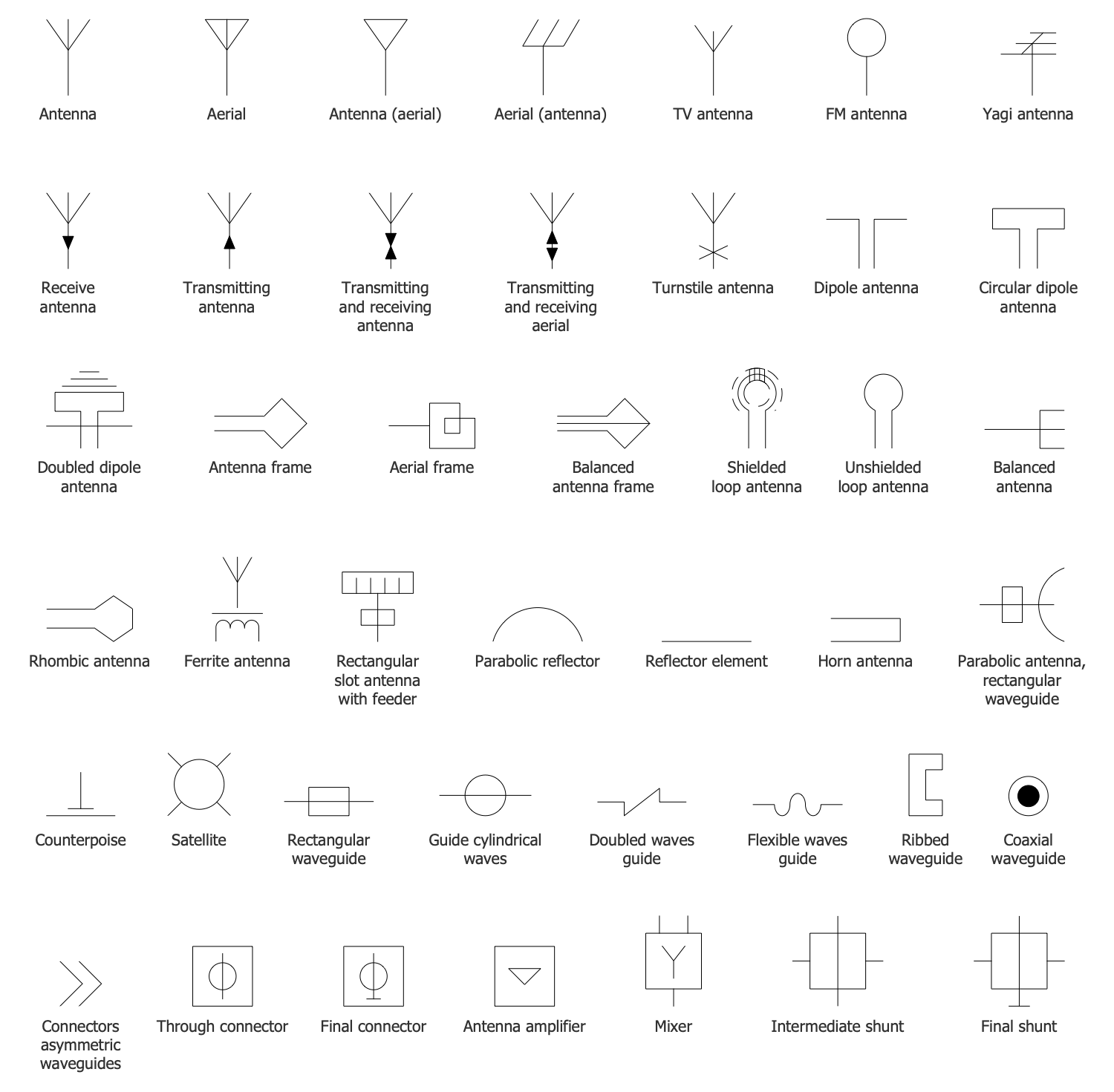
Design Elements — Antennas and Waveguides
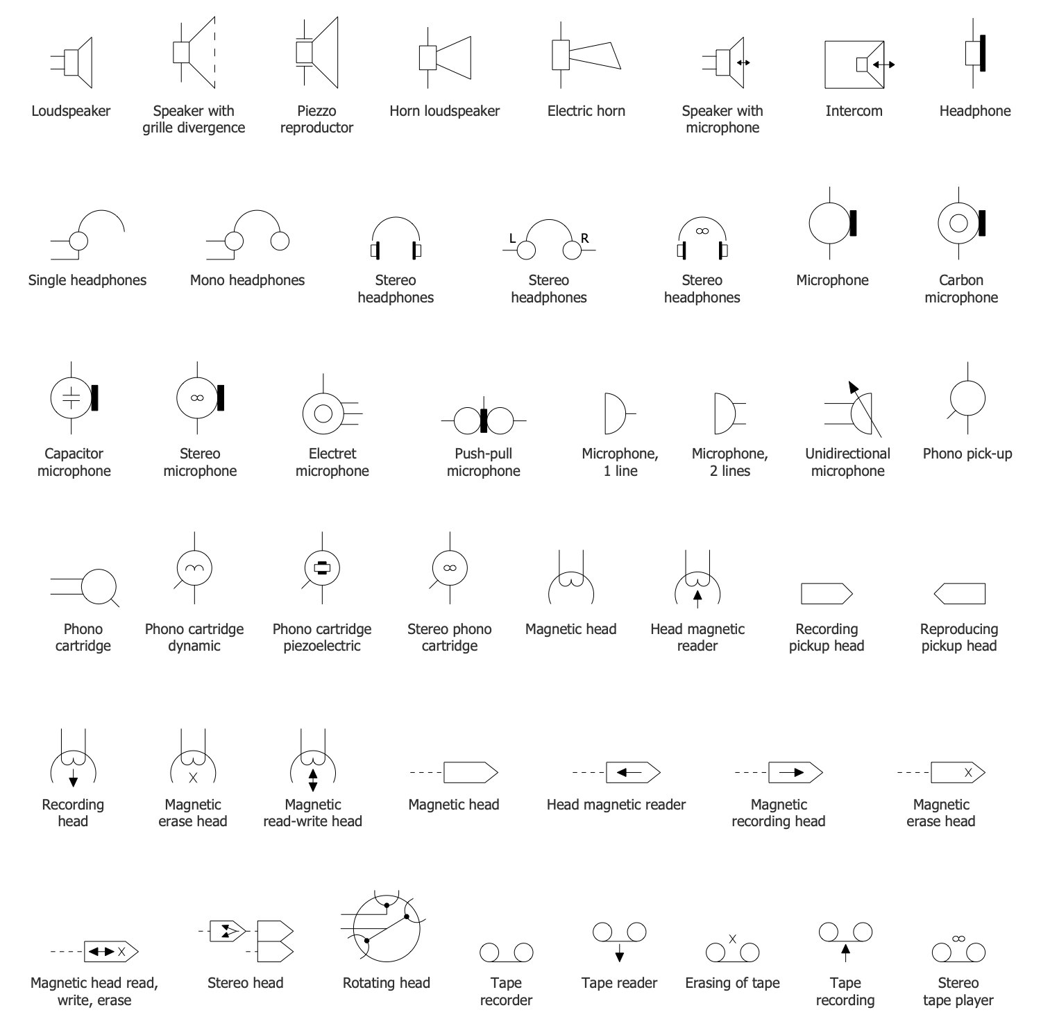
Design Elements — Audio Circuits
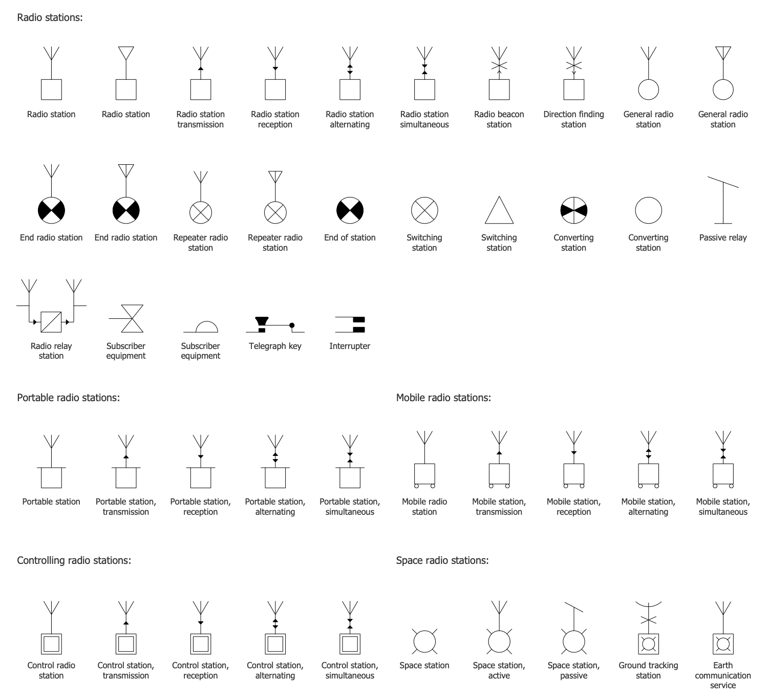
Design Elements — Radio Stations
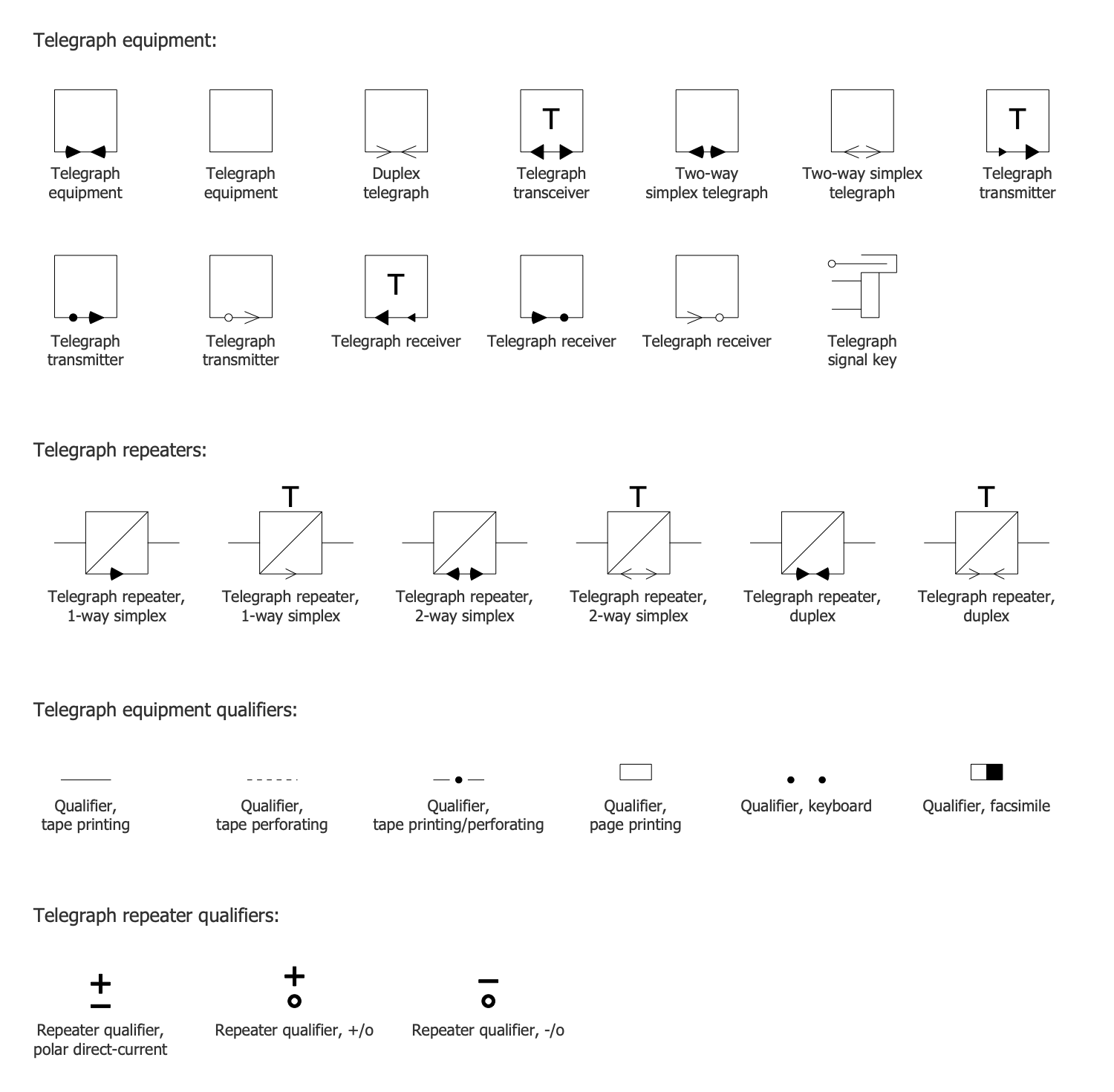
Design Elements — Telegraph Circuits
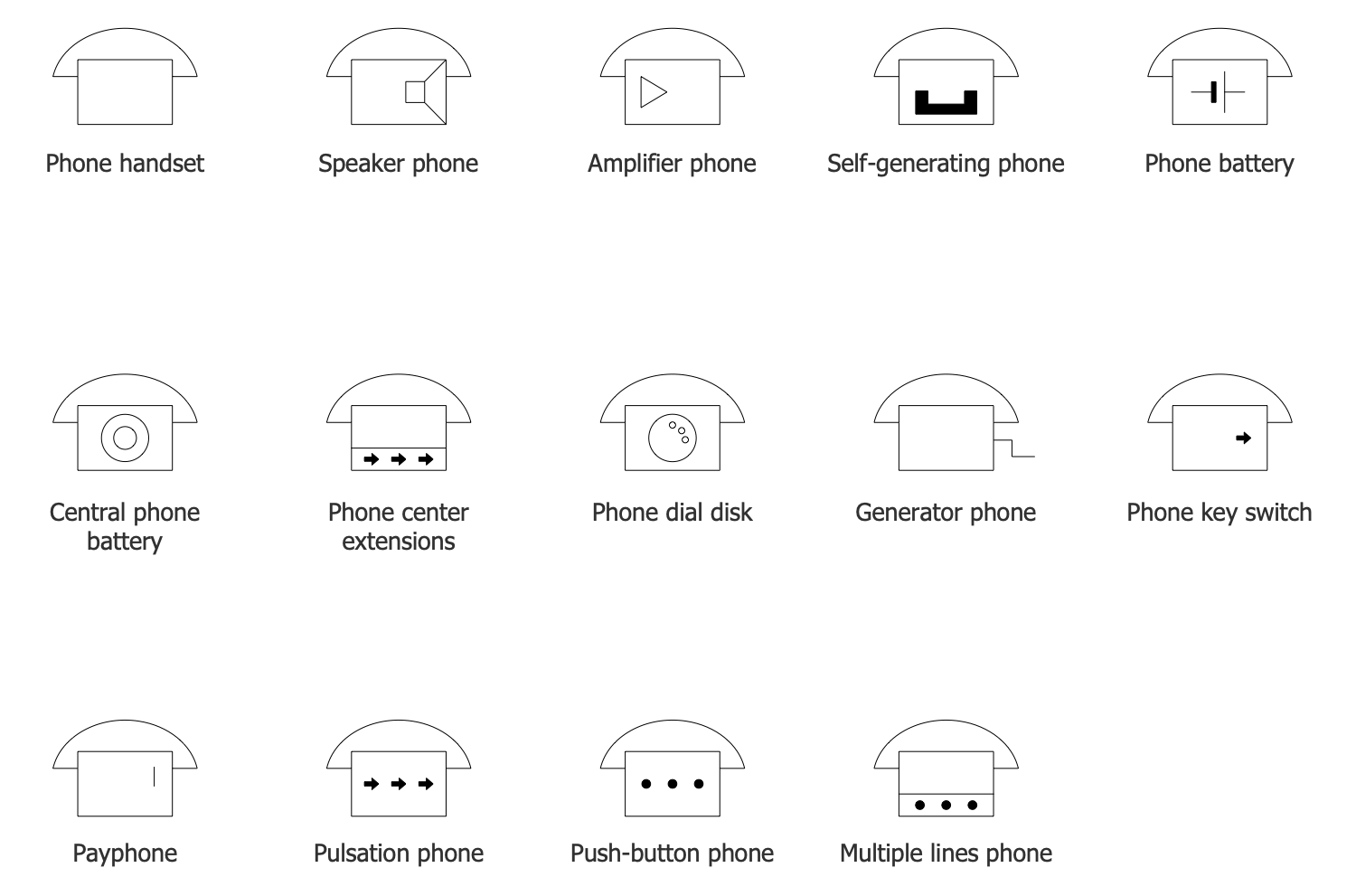
Design Elements — Telephone Handsets
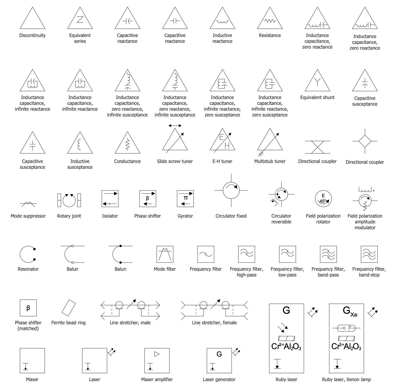
Design Elements — VHF, UHF, SHF
Design Elements — Video and TV Circuits
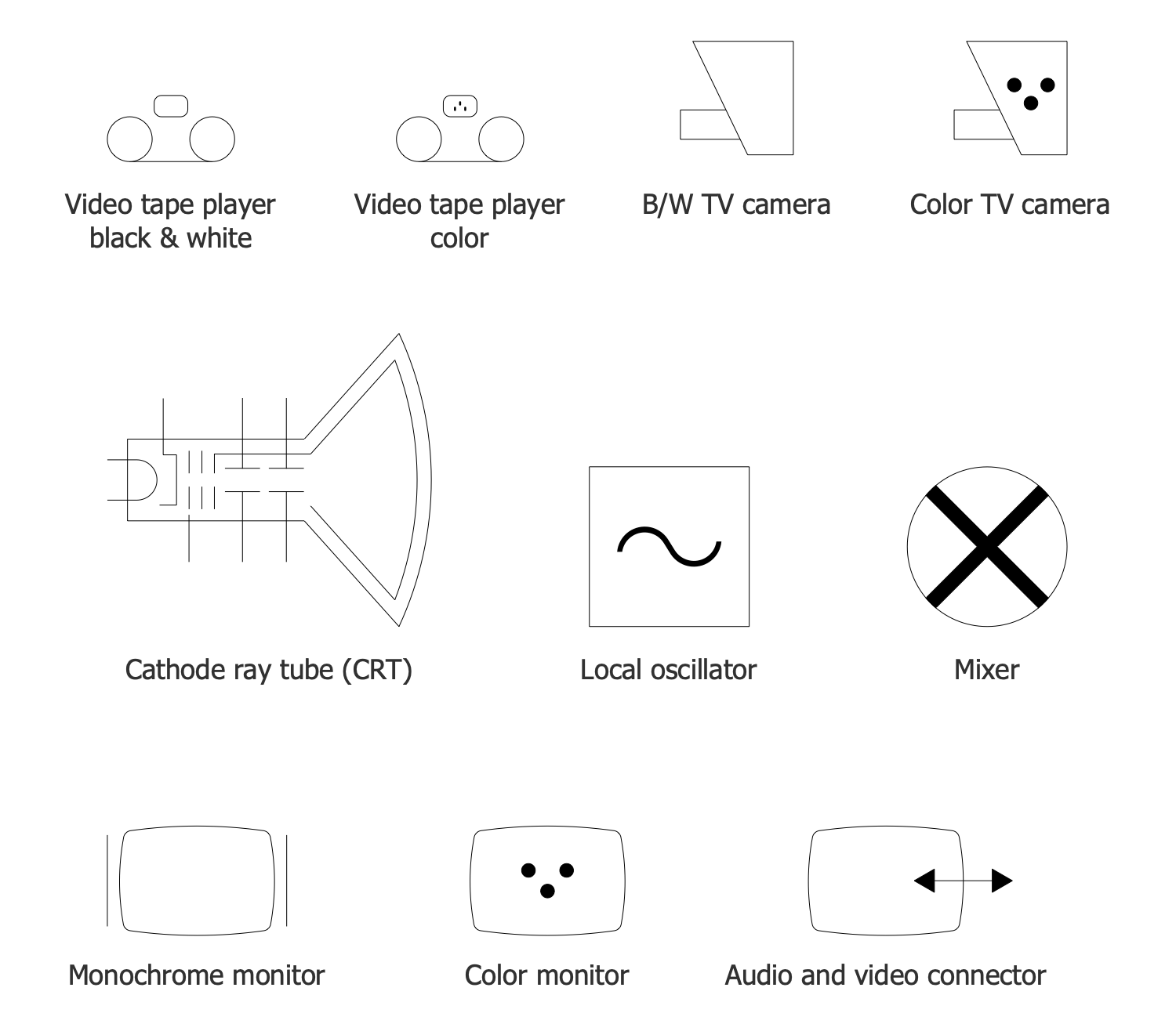
Telecom and AV Circuits Examples
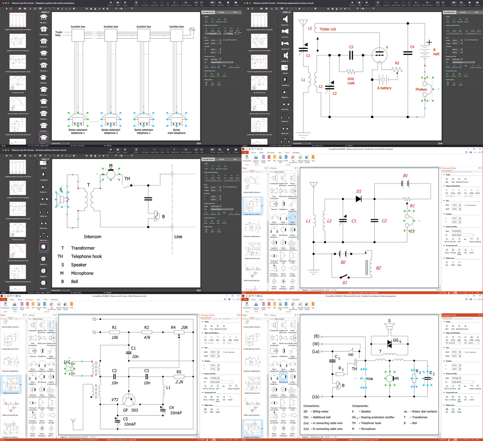
There are a few samples that you see on this page which were created in the ConceptDraw DIAGRAM application by using the Telecom and AV Circuits solution. Some of the solution's capabilities as well as the professional results which you can achieve are all demonstrated here on this page.
All source documents are vector graphic documents which are always available for modifying, reviewing and/or converting to many different formats, such as MS PowerPoint, PDF file, MS Visio, and many other graphic ones from the ConceptDraw Solution Park or ConceptDraw STORE. The Telecom and AV Circuits solution is available to all ConceptDraw DIAGRAM users to get installed and used while working in the ConceptDraw DIAGRAM drawing software.
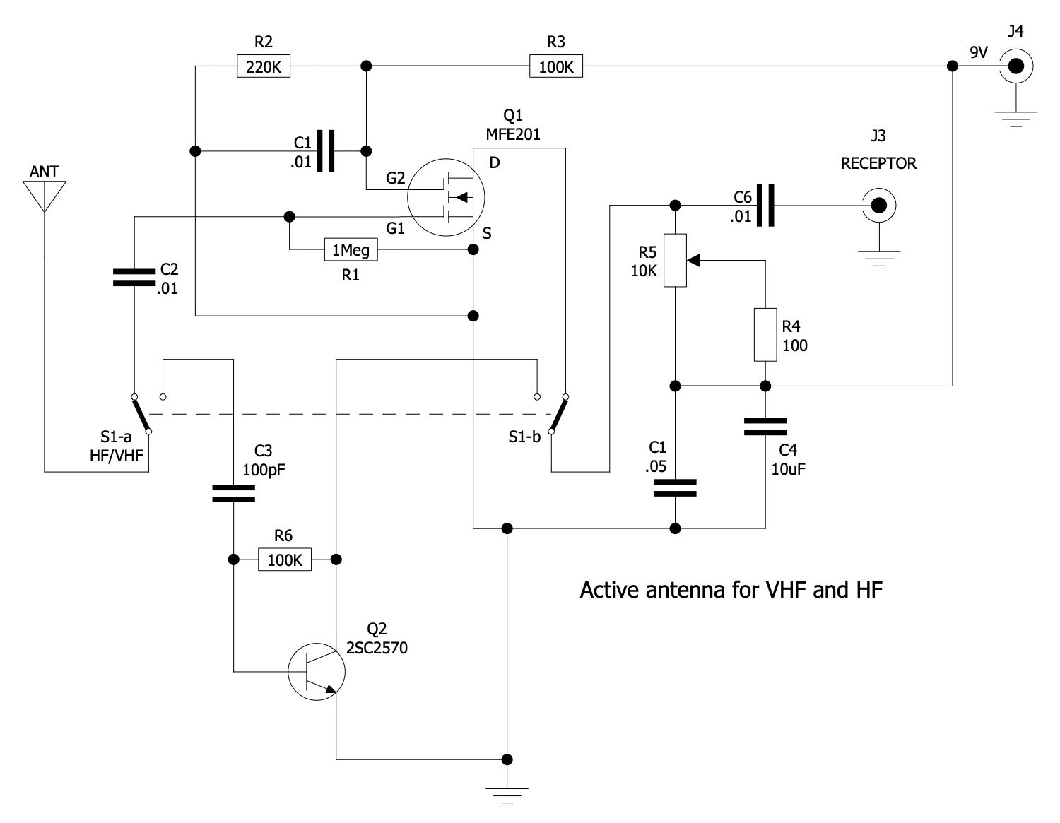
Example 1: Amplifier with VHF and HF Antenna
This diagram was created in ConceptDraw DIAGRAM using a combination of libraries from the Telecom and AV Circuits Solution. An experienced user spent 15 minutes creating this sample.
This sample shows an amplifier with active high frequency (VHF) and high frequency (HF) antennas. An amplifier is applied to increase the power of a signal, voltage, or current. It uses electric power from a power supply to raise the amplitude of the signal and provide a greater value at the output. There are used both separate devices and amplifiers embedded in electrical equipment. As for the amount of amplification, it is defined by its gain calculated as the ratio of output voltage to input one. Very high frequency (VHF) is used for the range of radio waves from 30 to 300 MHz with wavelengths of 1 to 10 meters. These waves are spread mainly by line-of-sight. VHF antennas are mainly short and easily installed on vehicles and handheld devices like transceivers, walkie-talkies, etc. High frequency (HF) uses radio waves from 3 and 30 megahertz MHz with wavelengths ranging from 10 to 1000 meters. These frequencies are suitable for long-distance communication on mountainous terrains and across intercontinental distances. Antennas for transmitting these waves emit horizontally polarized waves.
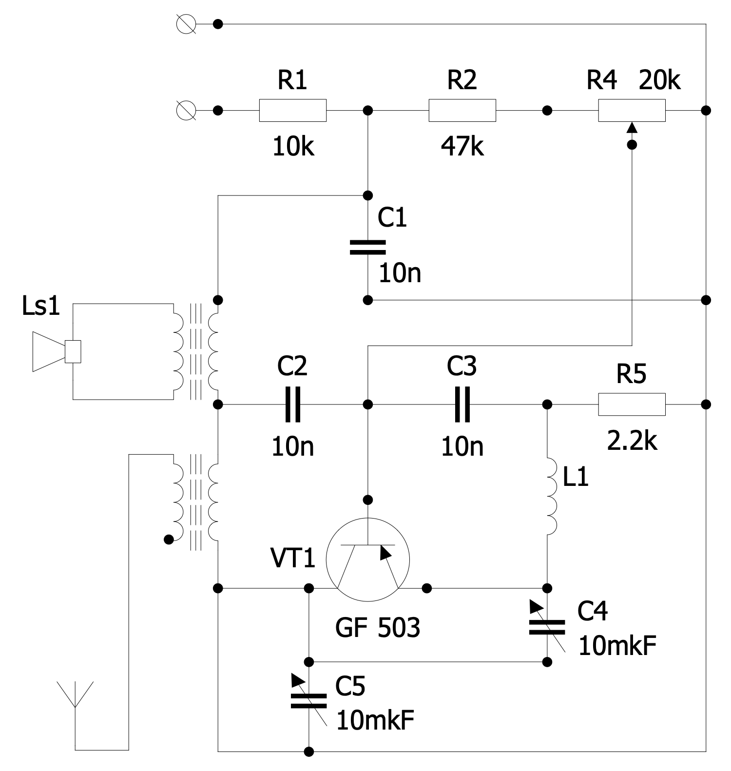
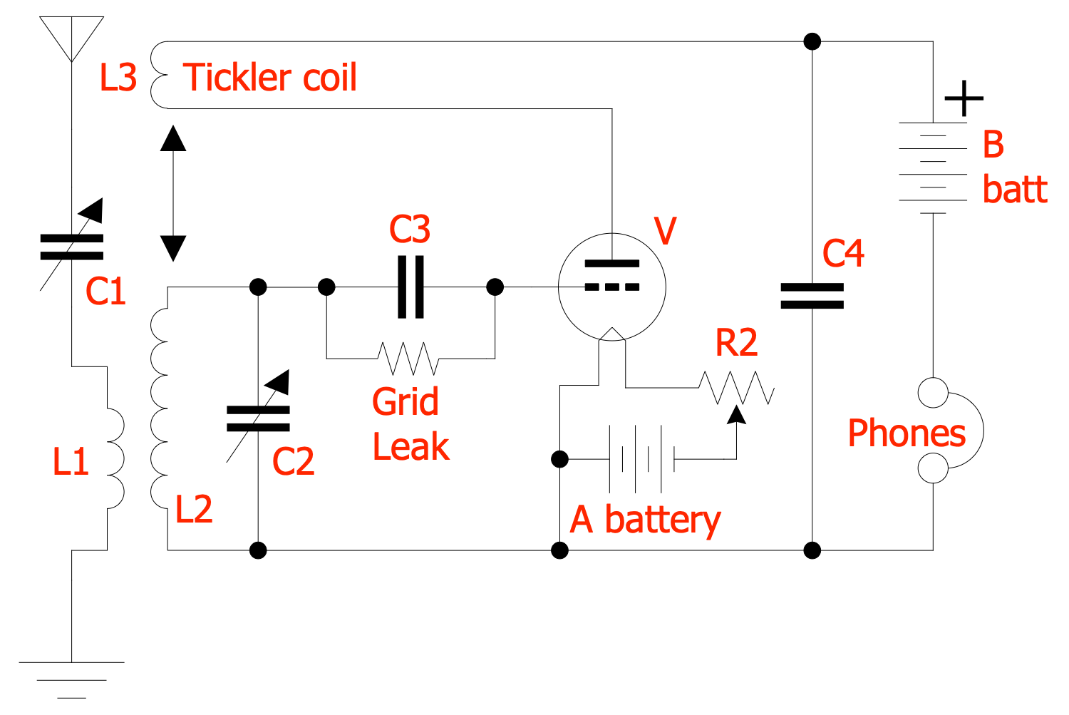
Example 2: Armstrong Regenerative Receiver Circuit
This diagram was created in ConceptDraw DIAGRAM using a combination of libraries from the Telecom and AV Circuits Solution. An experienced user spent 10 minutes creating this sample.
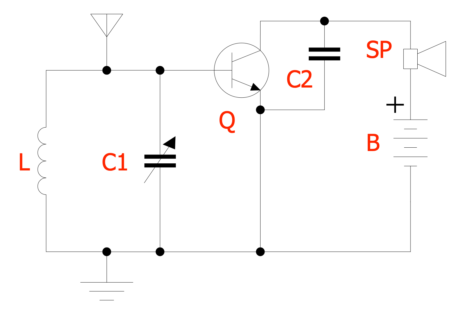
This sample diagram shows Armstrong regenerative receiver circuit with a single vacuum tube. This device was invented in 1912 by American engineer Edwin Armstrong and patented by him in 1914. It is an amplifier circuit with positive feedback (regeneration). The gain in Armstrong regenerative receiver is increased through using the tickler coil (L3). It feeds back some of the energy from the output plate circuit into the input grid circuit. By means of getting back the part of the output to the input, the amplification is increased time by time. Armstrong regenerative receiver requires a relatively small operating current and makes smooth the regeneration control. If enough energy is fed back into the circuit and sufficient amplification is provided, then undamped oscillations occur in the circuit. Therefore, the current is limited using a choke capacitor and adjusted to obtain the maximum gain of the input signal.
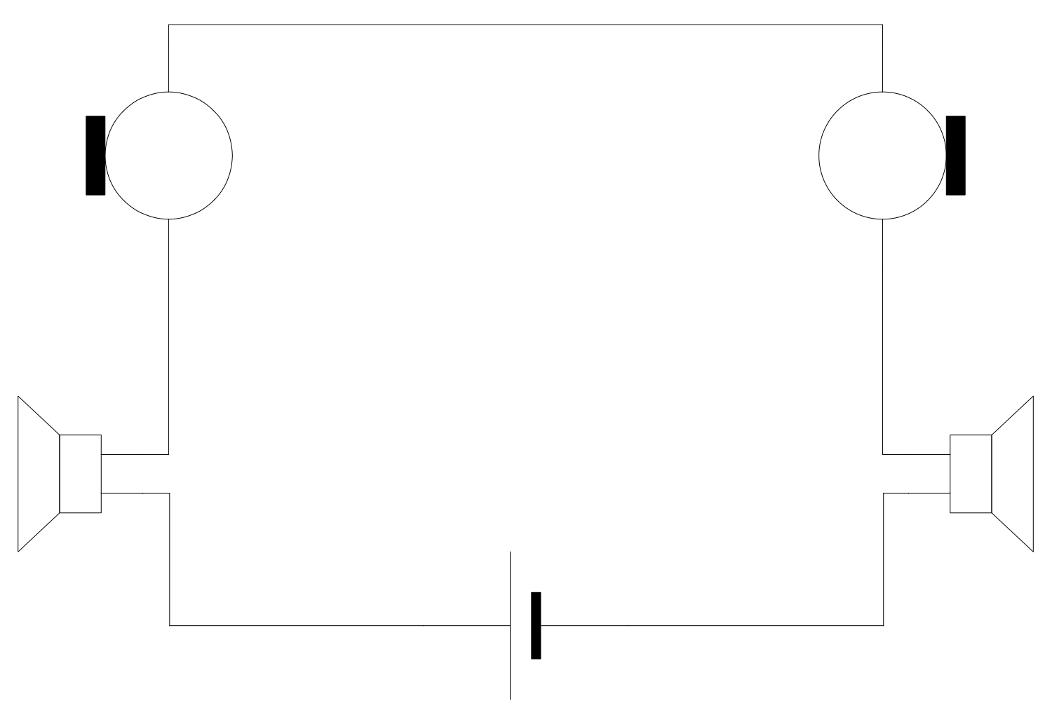
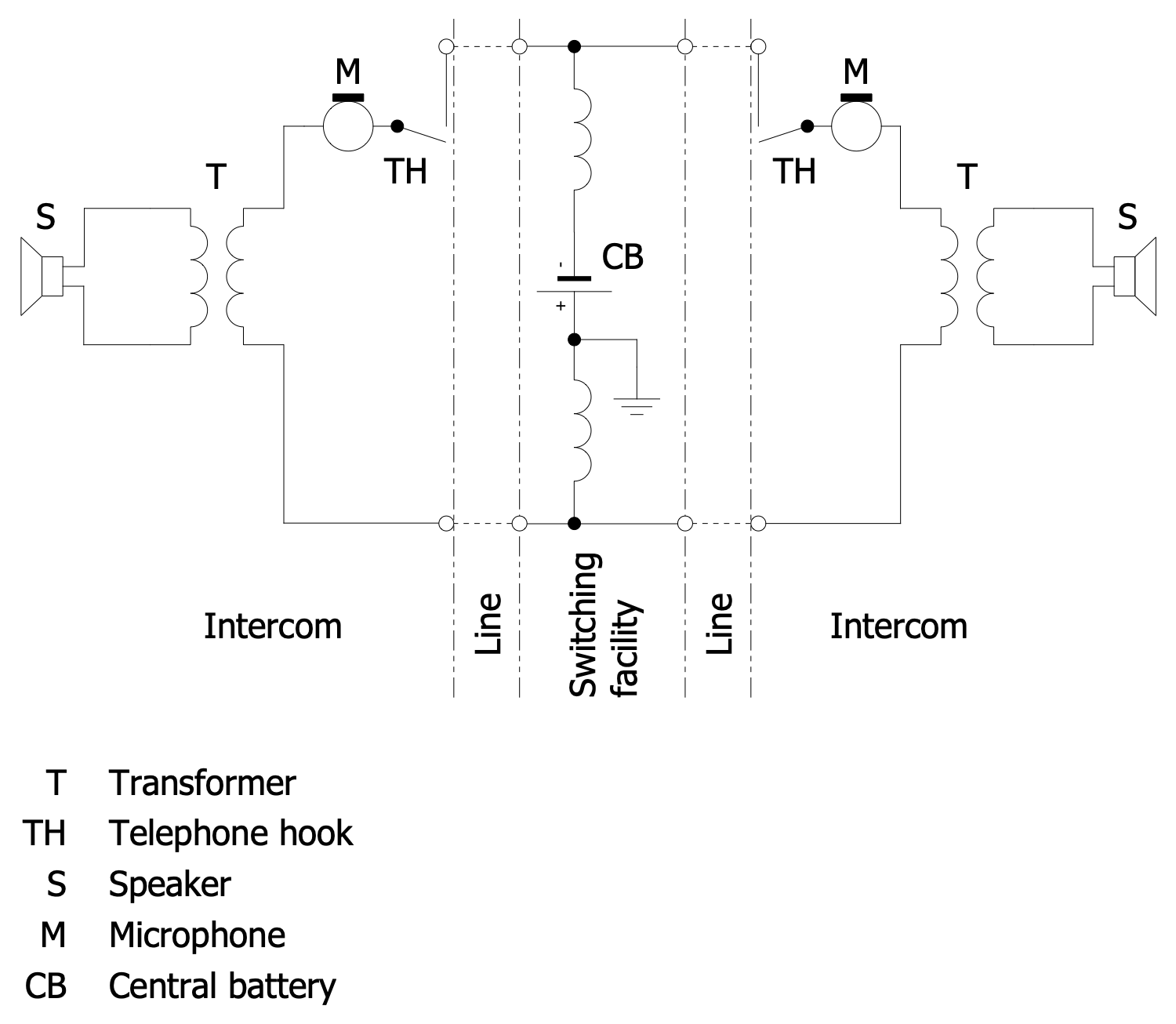
Example 3: CB Intercom Circuit
This diagram was created in ConceptDraw DIAGRAM using a combination of libraries from the Telecom and AV Circuits Solution. An experienced user spent 10 minutes creating this sample.
This telecom and TV diagram example shows a common battery (CB) intercom circuit. An intercom is a stand-alone voice communications system functioning within one or several buildings independently of the public telephone network. The intercoms are easily connected to control devices like signal lights or door latches, to video systems, computers, TCP/IP, public address loudspeaker systems, walkie-talkies, or other intercoms. They are installed both in apartment buildings with an exit from each apartment and in individual houses with a single connection. A common battery is an electrical power source used to energize simultaneously more than one circuit, system, electronic equipment, or other electronic component. It consists of a series of electrolytic cells and is usually installed in the center of the device it serves. Typically, its power is 48 V DC. A conventional battery may also include converters for converting commercial power to direct current with a rechargeable battery at the output.
Example 4: Common Battery Telephone Circuit
This diagram was created in ConceptDraw DIAGRAM using a combination of libraries from the Telecom and AV Circuits Solution. An experienced user spent 5 minutes creating this sample.
This sample shows a common battery telephone circuit. A telephone is a telecommunications device firmly entered in our life. It allows two or more users to communicate through a conversation at a far distance in real time. The built-in microphone and earphone are the main components of the telephone or its handset part. The microphone receives the sound waves, typically a human voice, and converts them into electronic signals. These signals are transmitted through cables and other communication channels to another user and then played back to him in the form of sound. Moreover, the telephone is a duplex device and transmits signals in both directions simultaneously. Essentially, headphones are the devices that play audible sound from far away. The phone also includes a shared battery, which is the source of electricity used to power the phone. Use the ConceptDraw DIAGRAM software to easily design both simple and complex telecom and television circuits, 3 way switch diagram, and more.
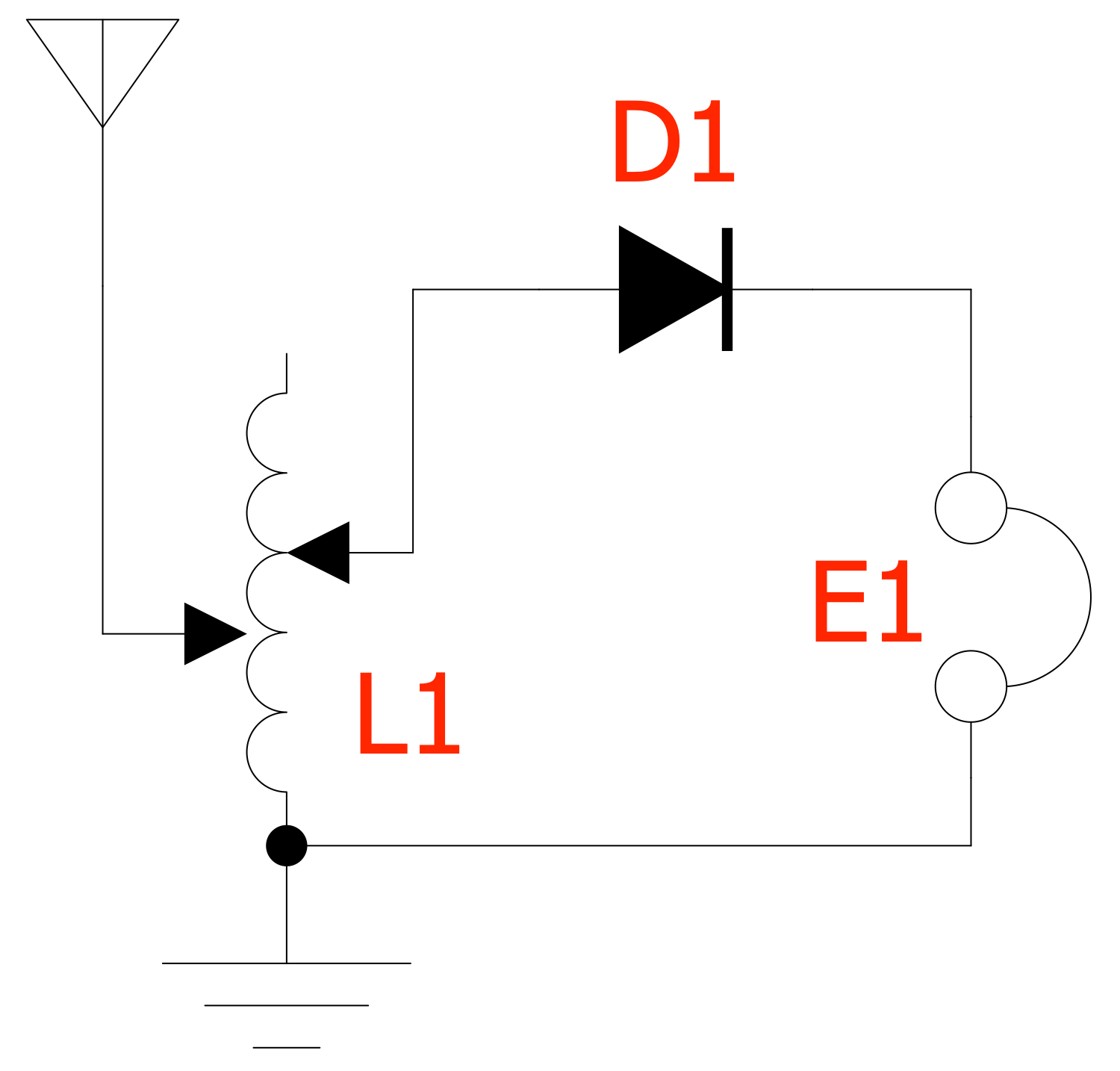
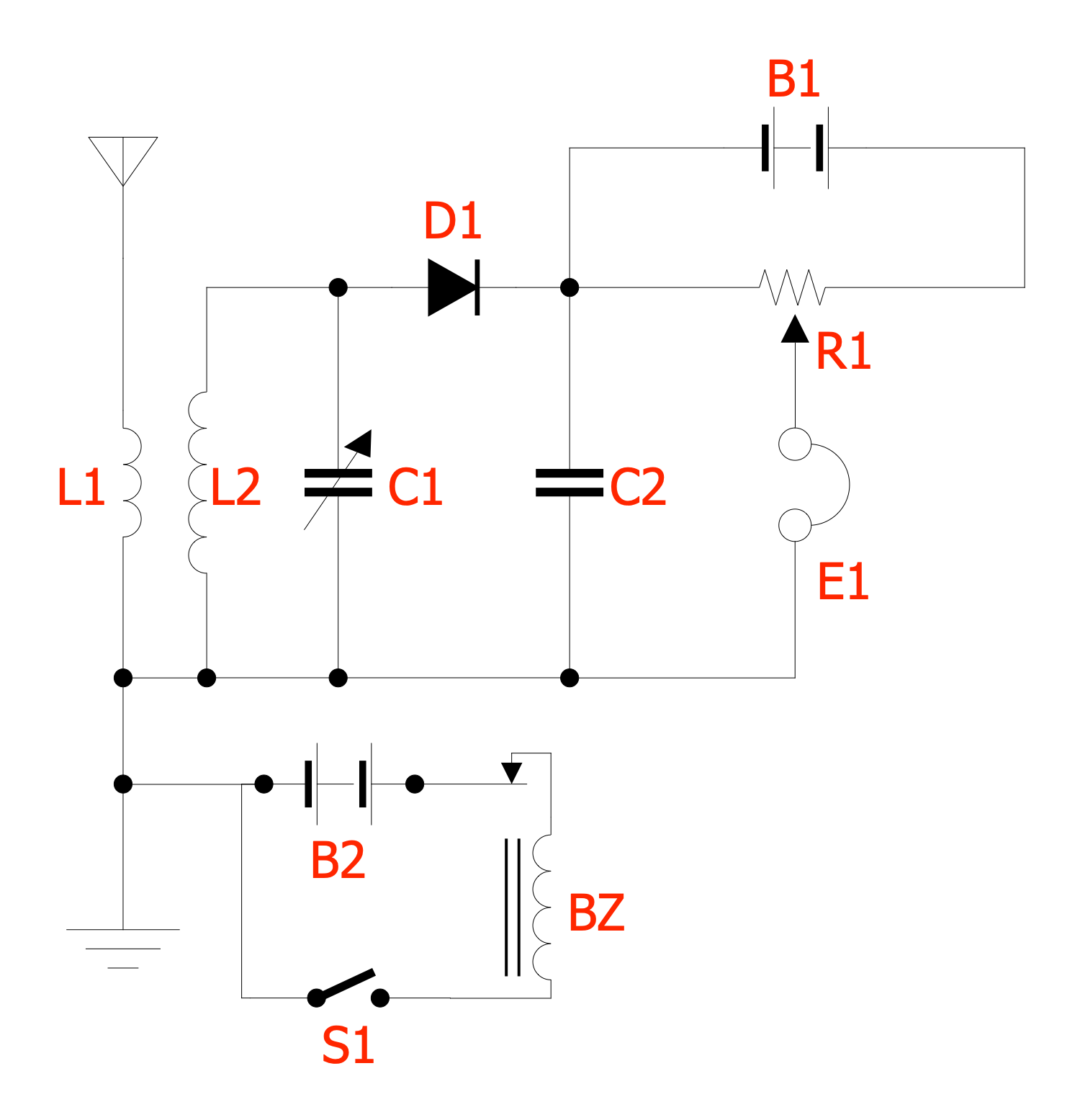
Example 5: Crystal Radio Circuit with Bias and Buzzer
This diagram was created in ConceptDraw DIAGRAM using a combination of libraries from the Telecom and AV Circuits Solution. An experienced user spent 10 minutes creating this sample.
This diagram sample shows a crystal radio receiver circuit with bias battery and testing buzzer. A crystal radio receiver is the simplest type of radio receiver made of just a few simple parts. It includes a coil of wire, a wire for an antenna, a capacitor, headphones, and a crystal detector made of a crystalline mineral. The crystal radio receiver uses only the power of the internal radio signal to reproduce the sound and does not require external power. The offered circuit was initially used with cat's whisker detectors in the wireless telegraphy. The detector battery allows improving sensitivity and a buzzer helps to set up the cat's whisker. The cat's whisker detector D1 is a diode made of a fine wire touching the crystal. Their point of contact acts like a semiconductor diode. The detector allows current to flow in one direction better than the other. The wire is dragged along the surface of the crystal until the detector starts working. The BZ buzzer acts as a radio transmitter and beeps when a desired location is found on the detector.
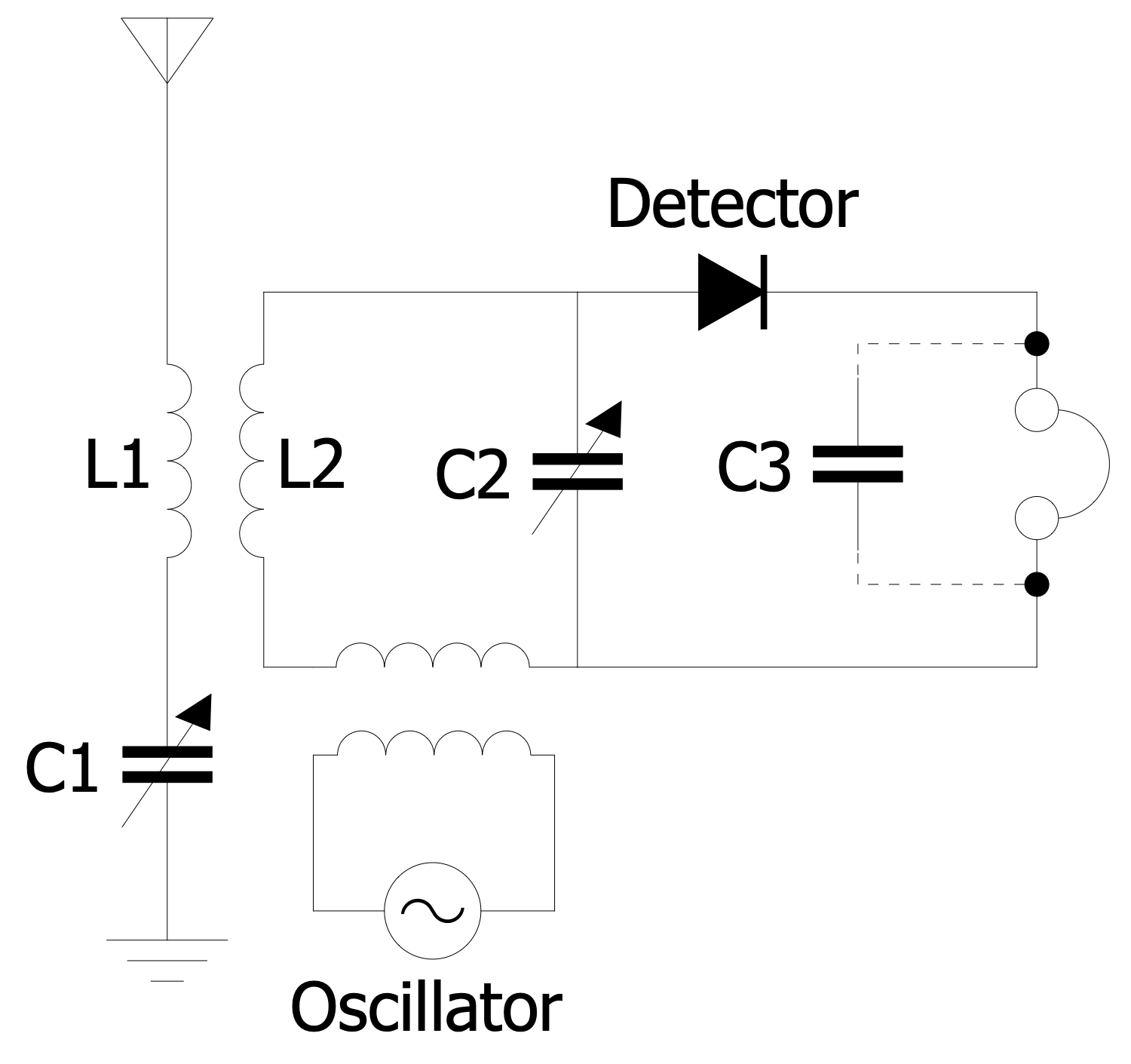
Example 6: Heterodyne Radio Receiver Circuit 1920
This diagram was created in ConceptDraw DIAGRAM using a combination of libraries from the Telecom and AV Circuits Solution. An experienced user spent 10 minutes creating this sample.
This sample shows a heterodyne radio receiver circuit. This type of radio receiver was invented in 1901 by Reginald Fessenden and was used for receiving continuous wave radiotelegraphy transmissions. The continuous wave radiotelegraph signal is transmitted at radio frequency fC and consists of Morse code pulses, including two types of pulses "dots" and "dashes". The carrier wave of these signals hasn't modulation. The signals are generated at a frequency fO that is offset from the carrier. The difference between the frequencies fH=fC−fO. That's why these signals aren't heard in the earphones of ordinary receivers. Sine wave radio signal and the radio signal from the antenna are applied to a rectifying detector (crystal detector). When two frequencies are mixed in the detector, a heterodyne frequency is generated. With a properly selected local oscillator frequency, it will be in the audio range and Morse code pulses in the form of musical beeps will be heard in the headphones. As a source of sinusoidal waves, a triode feedback generator on vacuum tubes is usually used. Today, instead of the Fessenden heterodyne oscillator, a beat frequency generator is used.
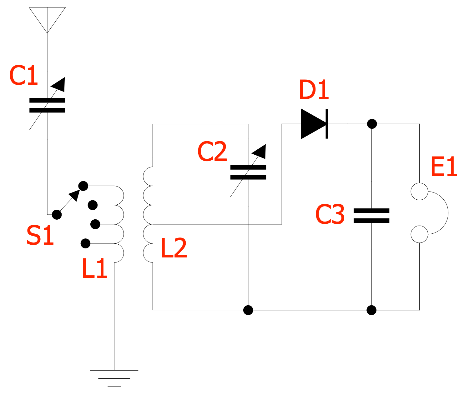
Example 7: Inductively Coupled Crystal Radio Receiver Circuit
This diagram was created in ConceptDraw DIAGRAM using a combination of libraries from the Telecom and AV Circuits Solution. An experienced user spent 10 minutes creating this sample.
This sample shows an inductively coupled crystal radio receiver circuit with impedance matching. This receiver is also called a "loose coupler" or "two circuit". The circuit includes the primary and secondary transformers L1 and L2 and the antenna coupling them to improve the poor selectivity. The crystal detector D1 is attached to a tap on L2 and is impedance matched to the tuned circuit. The L1 transformer resonates with the capacitance of the antenna and the primary tuning capacitor C1. The L2 transformer resonates with the secondary tuning capacitor C2. Each coil acts as a tuned circuit, they both interact with each other and provide more narrow bandwidth. To narrow the bandwidth and eliminate interference when it occurs, the coils are temporarily separated. One or both coils can have multiple taps, and switch S1 allows you to select the one you want. It is possible to adjust the ratio of revolutions and the transformation ratio to obtain the loudest sound in the E1 earphone.
Example 8: Microwave Radiometer Block Diagram
This diagram was created in ConceptDraw DIAGRAM using a combination of libraries from the Telecom and AV Circuits Solution. An experienced user spent 10 minutes creating this sample.
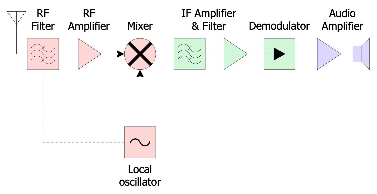
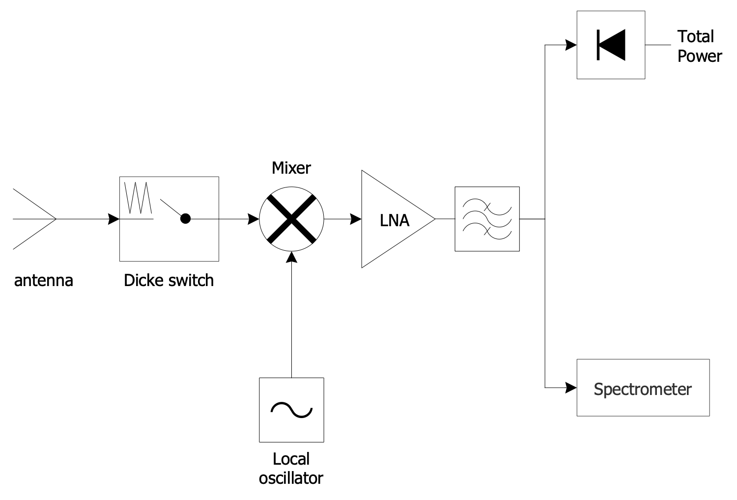
This block diagram sample shows a microwave radiometer (MWR) using the heterodyne principle. A microwave radiometer is a high-sensitive receiver that measures energy emitted at microwaves (from millimeter to centimeter wavelengths). These devices are used in a variety of environmental, engineering, and astronomy applications and allow measuring the thermally-emitted electromagnetic radiation. Due to them weather forecasting and climate monitoring are possible. Moreover, they include multiple receiving channels.The RF signal enters the antenna and is then down-converted to an intermediate frequency. The stable local oscillator signal is used for that. A low noise amplifier and bandpass filtering help to amplify the signal. The signal detection is carried out by dividing it into several frequency bands using a spectrometer. The Dicke switch is used for high-frequency calibrations. All vector stencils required for electrical engineering, to design effectively your telecom and TV diagramsare available in the ConceptDraw Telecom and AV Circuits solution libraries.
Example 9: Multipath TV Ghost
This diagram was created in ConceptDraw DIAGRAM using a combination of libraries from the Telecom and AV Circuits Solution. An experienced user spent 5 minutes creating this sample.
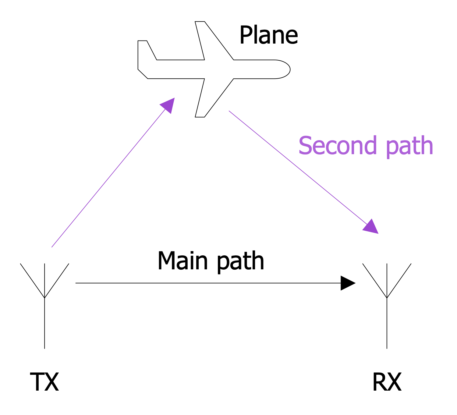
This sample is dedicated to the effects appearing in TV systems and a multipath TV ghost, in particular. A multipath is a kind of radio communication phenomenon. It is a spread of the radio signals when they reach the receiving antenna by two or more paths. There are many reasons for the multipath. Among the main ones are ionospheric reflection and refraction, reflection from water bodies, mountains, buildings, and other terrestrial objects, atmospheric ducting, and more. However, some effects, like multipath interference or multipath distortion, or ghosting accompany the multipath. The interference or a phase shifting of the signal is observed when a signal is received over more than one path. In turn, the destructive interference can cause fading and weakness of a radio signal. The effect of ghosting shown in this diagram occurs in AN UHF TV systems when a duplicate of the transmitted image (ghost) is offset in position, usually horizontally to the right, and superimposed over the main image. It is a result of passing a TV signal to a receiving antenna TV through two different paths with a difference in time.
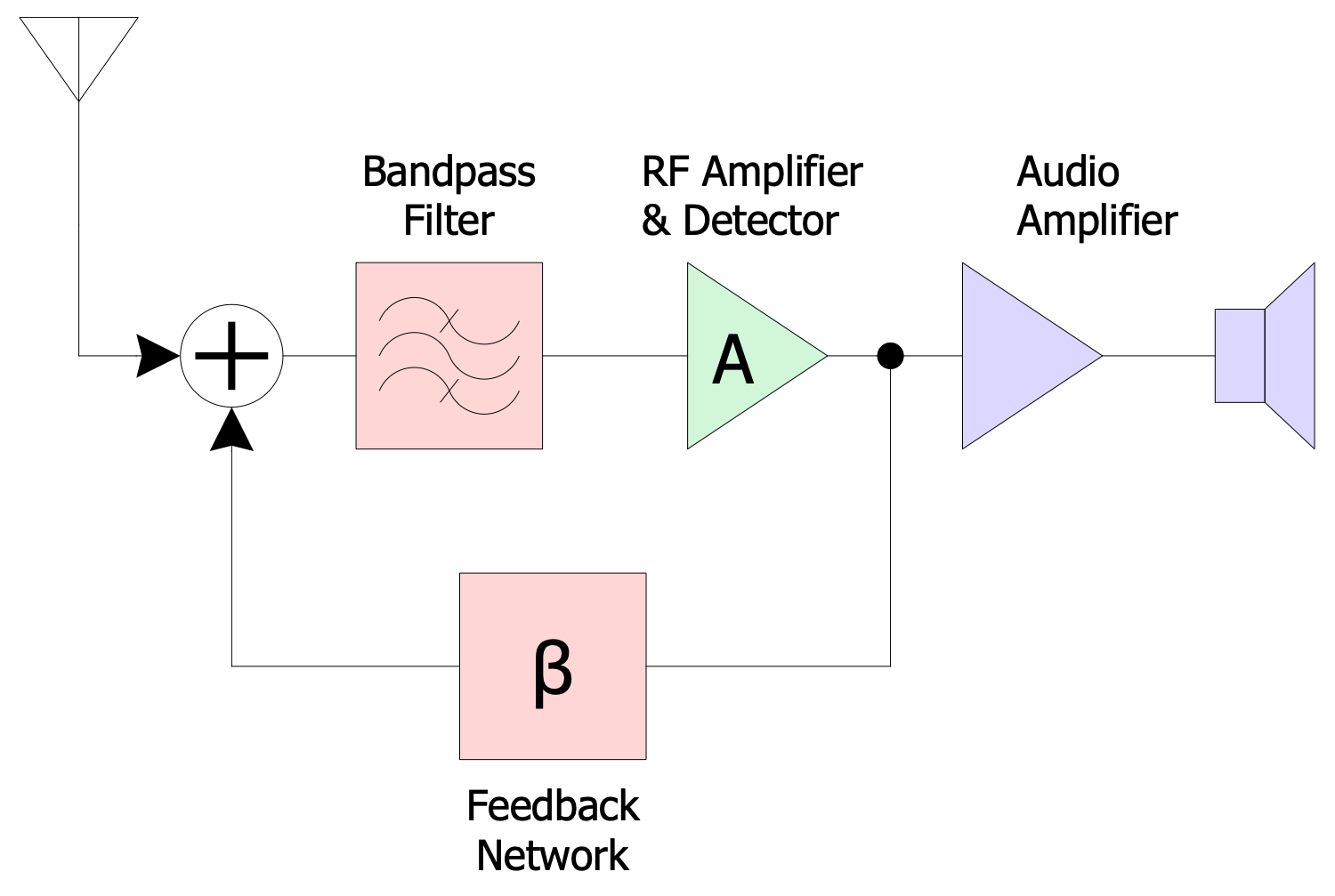
Example 10: Reflex Receiver Block Diagram
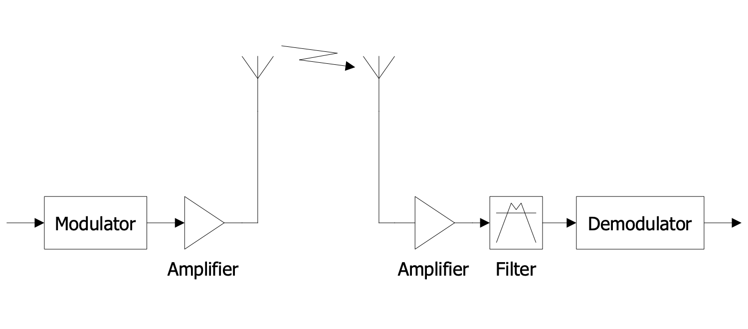
This diagram was created in ConceptDraw DIAGRAM using a combination of libraries from the Telecom and AV Circuits Solution. An experienced user spent 5 minutes creating this sample.
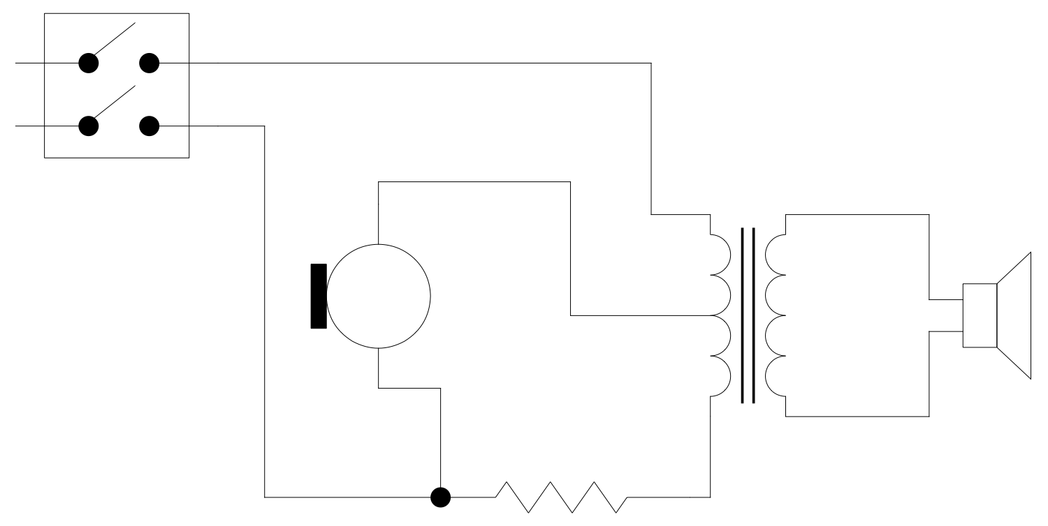
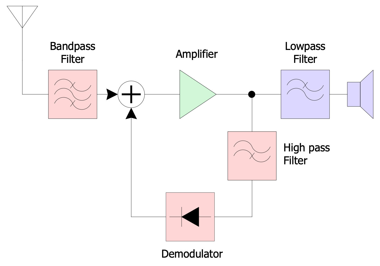
This block diagram sample shows a simple reflex radio receiver. The amplifier functions as a tuned radio frequency (TRF) receiver in this circuit and provides the amplification of both high-frequency radio signal (RF) and low-frequency audio signal (AF). The RF signal flows from the antenna to a tuned circuit through the bandpass filter. Then, it passes through an amplifier consisting of one or more vacuum tubes or transistors. After that, the signal pass to the demodulator through the high pass filter. The main purpose of a demodulator is to extract an audio frequency signal from a radio carrier wave. The signal is then returned to the input of the amplifier and passed through the same amplifier for re-amplification. At the output of the amplifier, the signal passes through the low-pass filter and then goes to the headphones. Both single-stage and multi-stage amplifiers are used. As a result, the use of an amplifier makes it possible to reduce the number of active devices, lamps, transistors and, as a result, the cost of the entire structure.
Example 11: Simplified Circuit Diagram of Telephone Apparatus
This diagram was created in ConceptDraw DIAGRAM using a combination of libraries from the Telecom and AV Circuits Solution. An experienced user spent 15 minutes creating this sample.
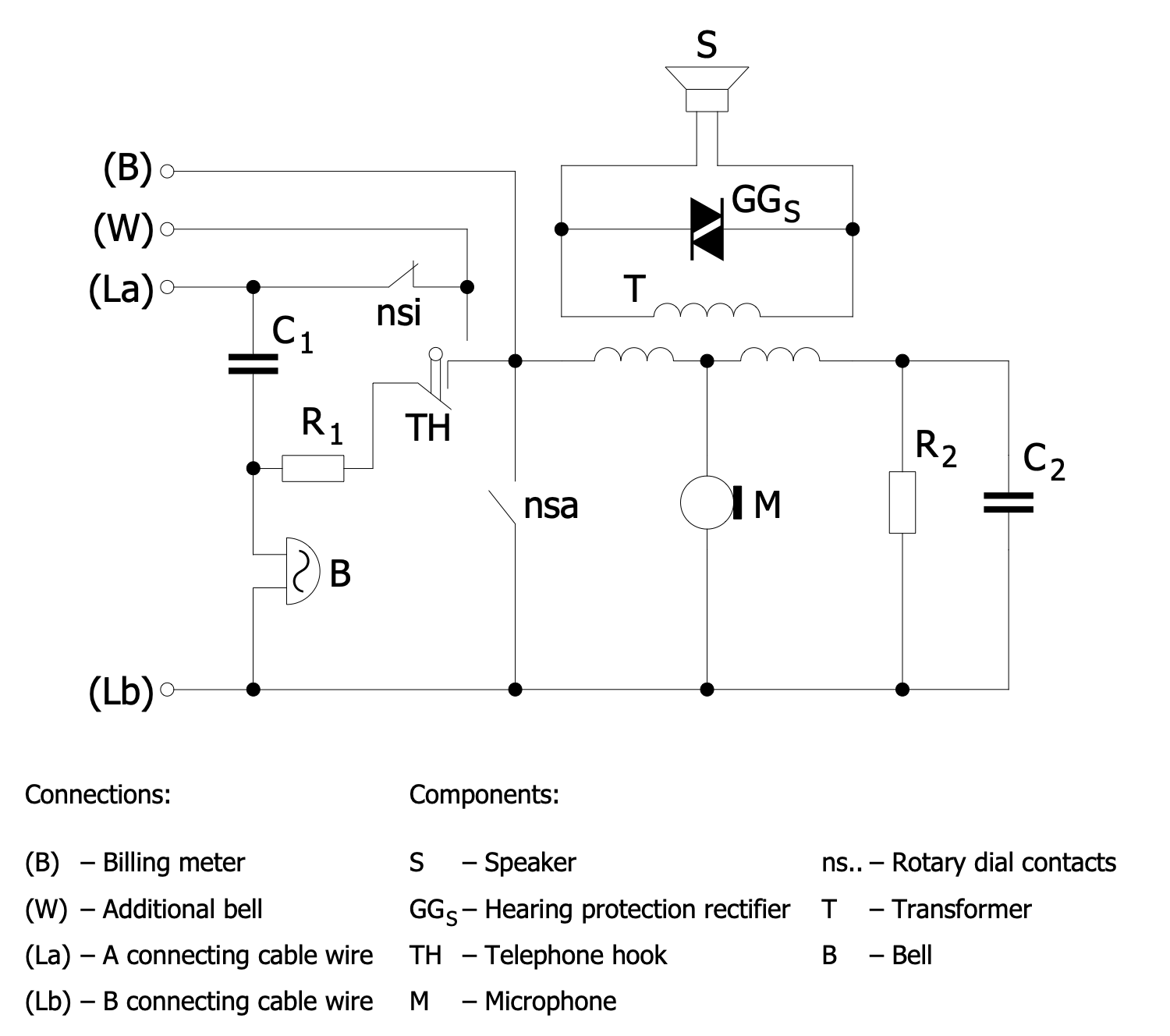
This telecom and TV diagram sample shows a simplified circuit diagram of the telephone apparatus. This equipment includes a lot of components, but the key ones are a microphone and an earphone embedded in a telephone hook. A microphone is a transmitter, it catches sounds and speech, and converts sound waves to electrical signals. Then the signals are sent through a telephone network. In turn, an earphone is a receiver, it catches these signals in a distant location, converts them, and reproduces the audible sounds and voice. Among the other components are transformer, hearing protection rectifier, bell, billing meter. This schematic was used for the telephones of the fixed-line type with a rotary dial, that's why the rotary dial contacts are also included in a schematic. The dial was located either on a base unit or a handset. The parts of the telephone apparatus are connected with cable wires.
More Examples:
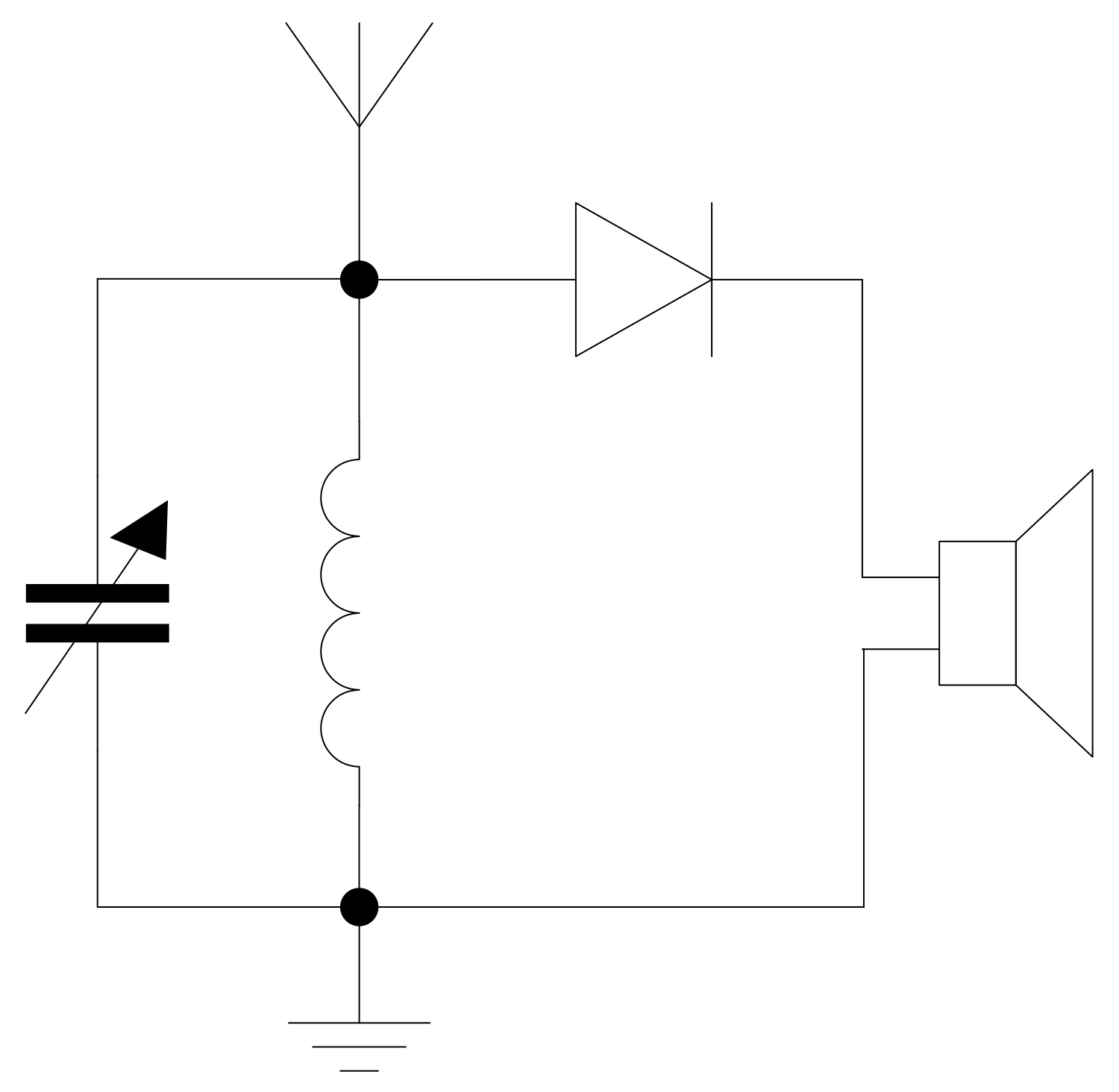
AM Radio Receiver Circuit
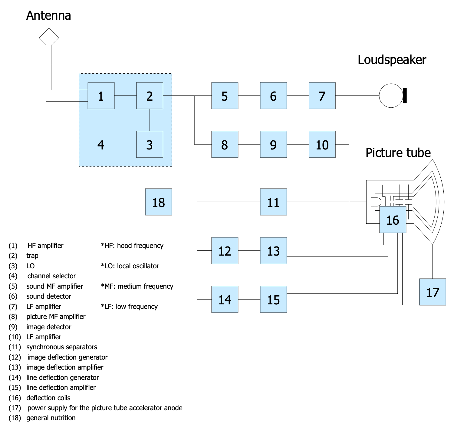
Black and White TV Receiver Block Diagram
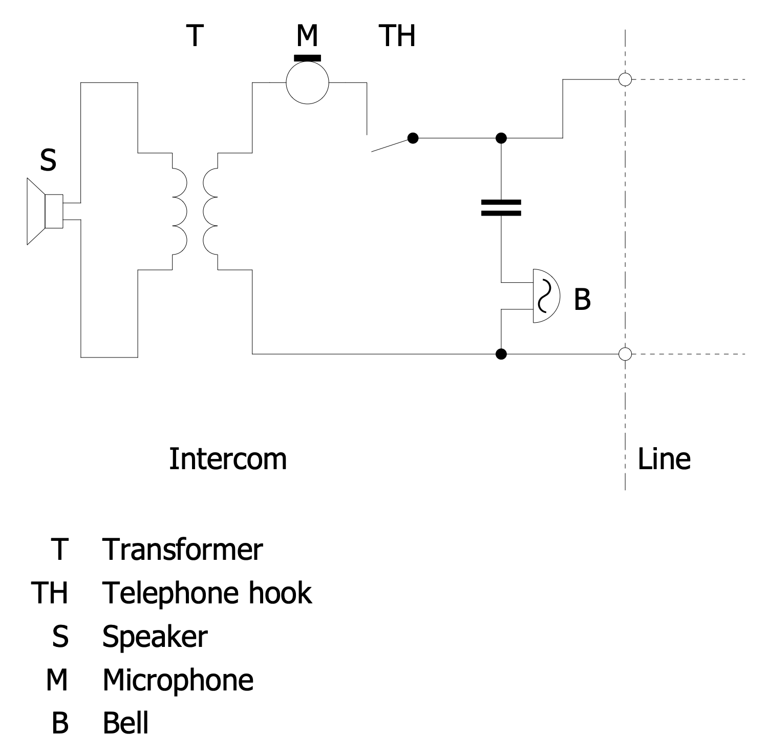
Common Battery Intercom Circuit
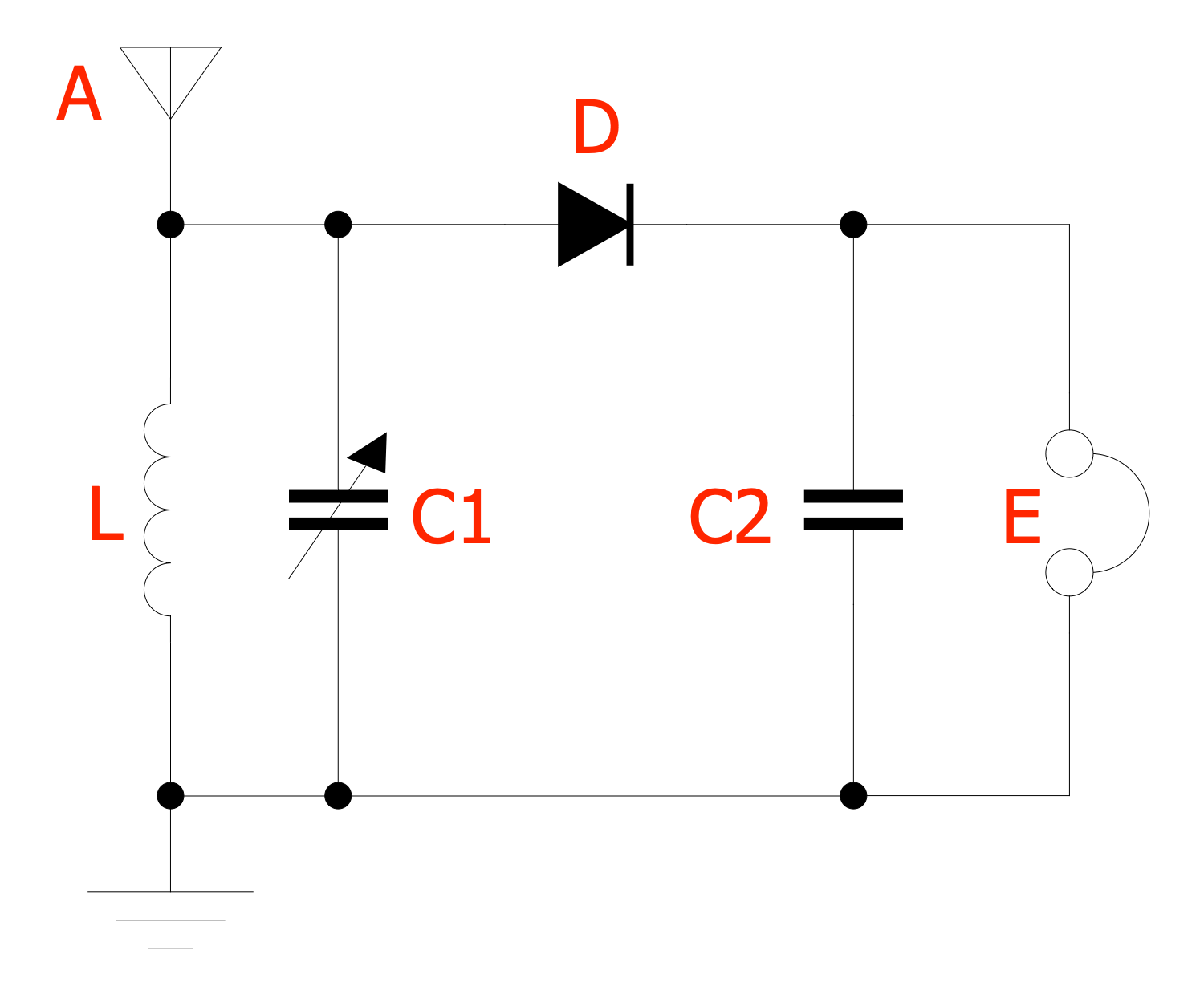
Crystal Radio Circuit
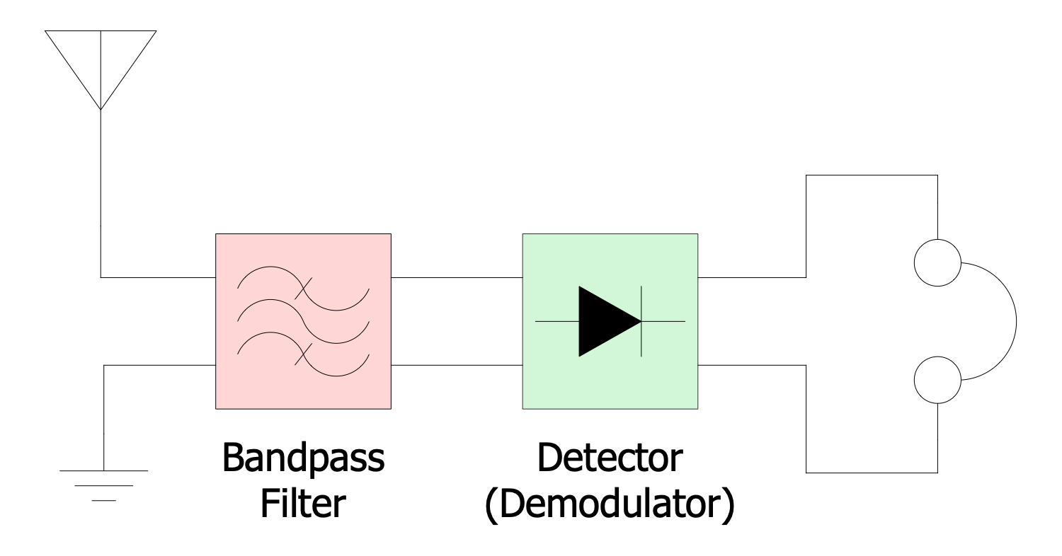
Crystal Radio Receiver Block Diagram"
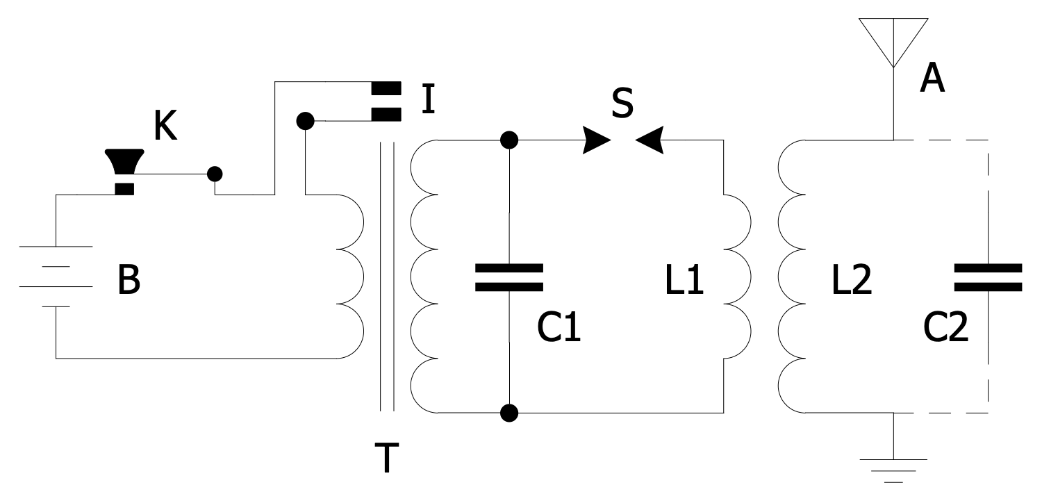
Inductively Coupled Spark Gap Transmitter Circuit
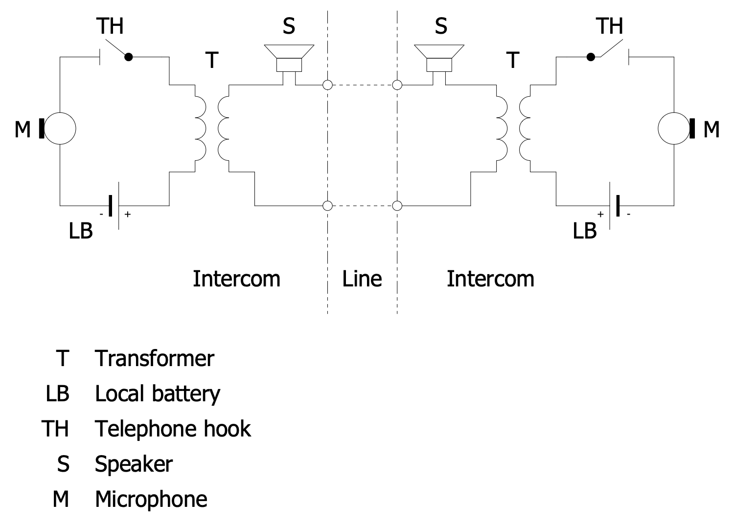
Local Battery Intercom Circuit Diagram
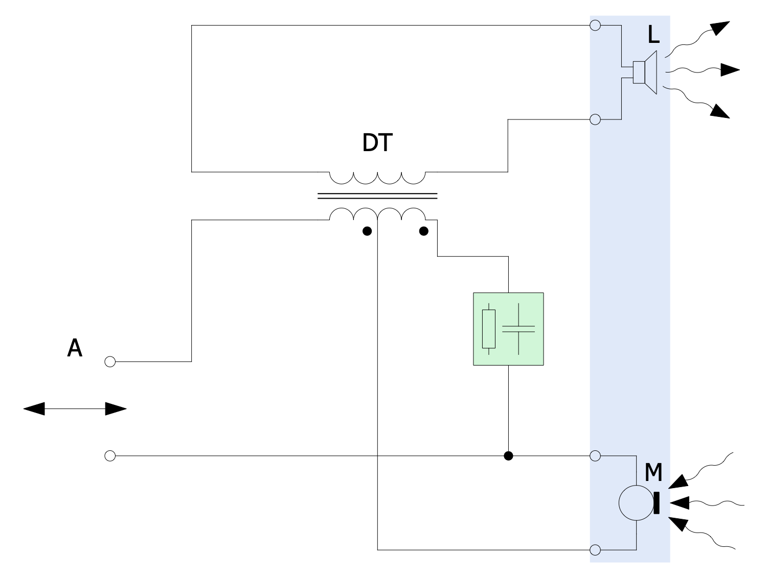
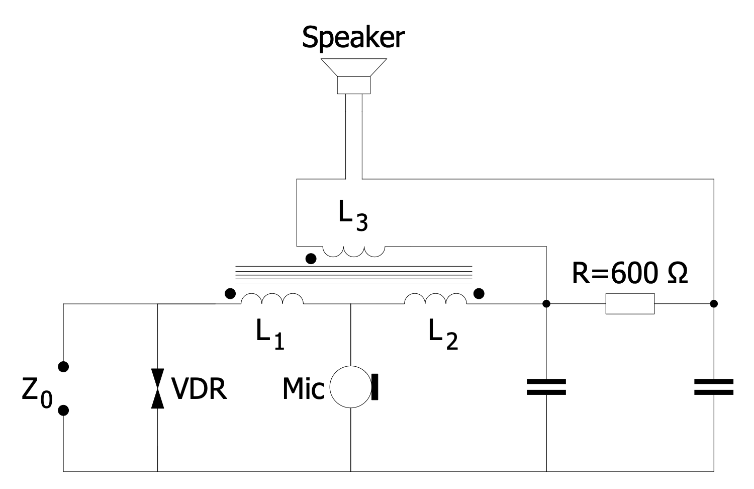
Telephone Hybrid Circuit
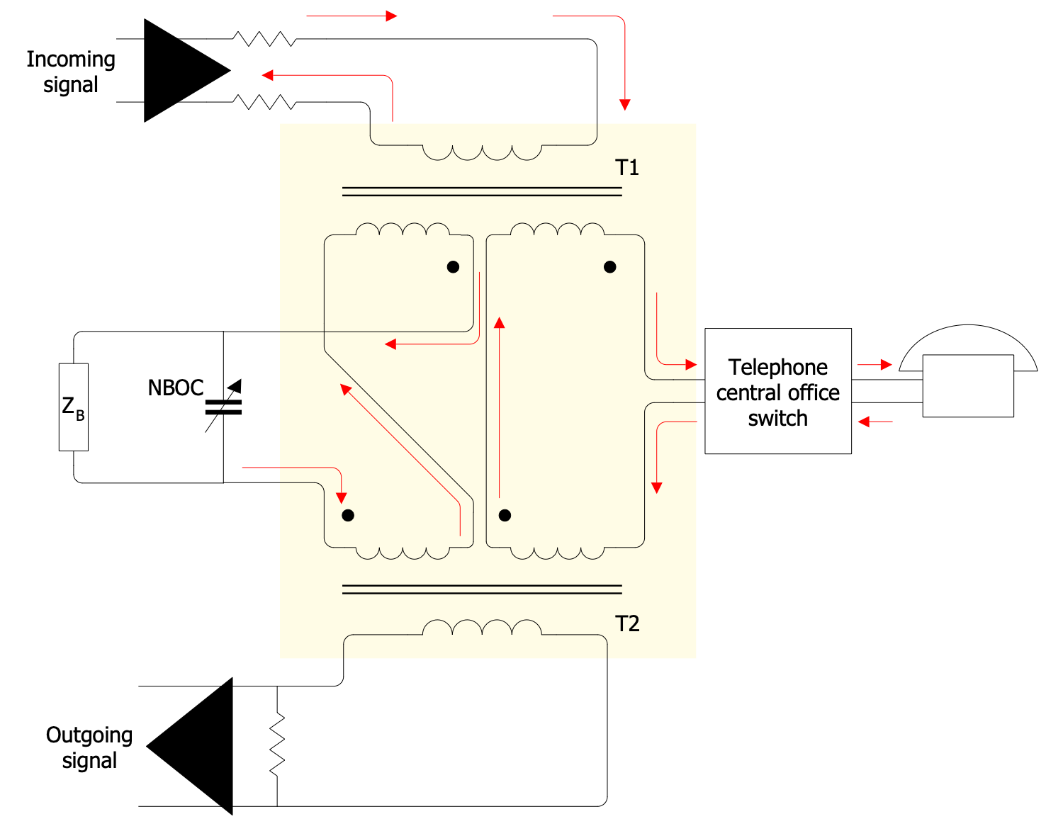
Telephone Hybrid Transformer
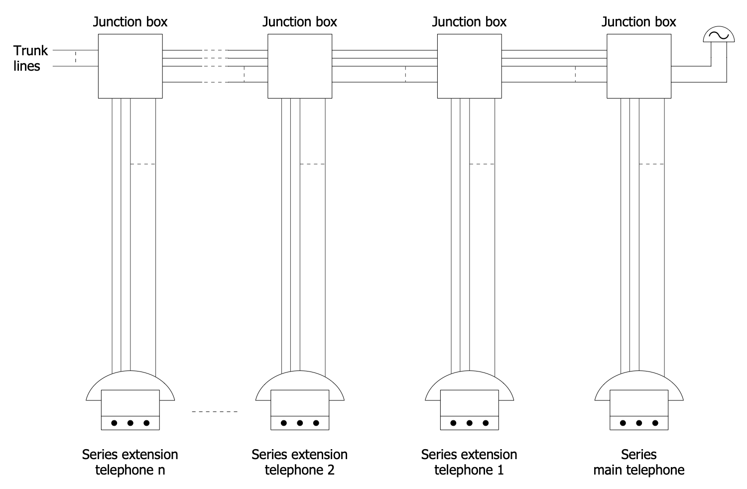
Active Directory Diagram — Tree and Forest
Inside
What I Need to Get Started
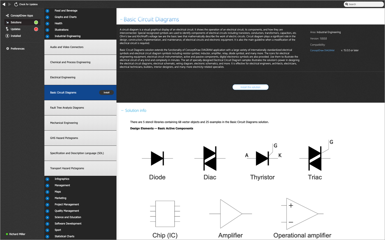
Both ConceptDraw DIAGRAM diagramming and drawing software and the Telecom and AV Circuits solution can help creating the illustrations the technical documentation of an engineering projects you need. The Telecom and AV Circuits solution can be found in the Industrial Engineering area of ConceptDraw STORE application that can be downloaded from this site. Make sure that both ConceptDraw DIAGRAM and ConceptDraw STORE applications are installed on your computer before you get started.
How to install
After ConceptDraw STORE and ConceptDraw DIAGRAM are downloaded and installed, you can install the Telecom and AV Circuits solution from the ConceptDraw STORE.
Start Using
To make sure that you are doing it all right, use the pre-designed symbols from the stencil libraries from the solution to make your drawings look smart and professional. Also, the pre-made examples from this solution can be used as drafts so your own drawings can be based on them. Using the samples, you can always change their structures, colors and data.
