- Electric and Telecom Plans Free
- Fire and Emergency Plans Free
- Floor Plans Free
- Plant Layout Plans Free
- School and Training Plans Free
- Seating Plans Free
- Security and Access Plans Free
- Site Plans Free
- Sport Field Plans Free
- Cafe and Restaurant Floor Plans $25
- Gym and Spa Area Plans $49
- HVAC Plans $49
- Landscape & Garden $49
- Office Layout Plans $25
- Plumbing and Piping Plans $49
- Reflected Ceiling Plans $49
- Tilt and Turn Windows $25
- Agriculture Infographics $49
- Economy Infographics $25
- Education Infographics $25
- Energy Industry Infographics $25
- Financial Infographics $25
- Green Energy $25
- Management Infographics $25
- Marketing Infographics $25
- Mass Media Infographics $25
- Oil and Gas $25
- Politics Infographics $25
- Travel Infographics $25
- Business Process Diagrams Free
- Business Process Mapping Free
- Classic Business Process Modeling Free
- Cross-Functional Flowcharts Free
- Event-driven Process Chain Diagrams Free
- IDEF Business Process Diagrams Free
- Logistics Flow Charts Free
- Workflow Diagrams Free
- Business Intelligence Dashboard $99
- Business Process Workflow Diagrams $49
- Healthcare Management Workflow Diagrams $49
- Logistic Dashboard $49
- ConceptDraw Dashboard for Facebook Free
- Mind Map Exchange Free
- MindTweet Free
- Note Exchange Free
- Project Exchange Free
- Social Media Response Free
- Active Directory Diagrams Free
- AWS Architecture Diagrams Free
- Azure Architecture Free
- Cisco Network Diagrams Free
- Cisco Networking Free
- Cloud Computing Diagrams Free
- Computer Network Diagrams Free
- Google Cloud Platform Free
- Interactive Voice Response Diagrams Free
- Network Layout Floor Plans Free
- Network Security Diagrams Free
- Rack Diagrams Free
- Telecommunication Network Diagrams Free
- Vehicular Networking Free
- Wireless Networks Free
- Internet of Things $30
- Comparison Dashboard Free
- Composition Dashboard Free
- Correlation Dashboard Free
- Frequency Distribution Dashboard Free
- Meter Dashboard Free
- Spatial Dashboard Free
- Status Dashboard Free
- Time Series Dashboard Free
- Basic Circle-Spoke Diagrams Free
- Basic Circular Arrows Diagrams Free
- Basic Venn Diagrams Free
- Block Diagrams Free
- Concept Maps Free
- Family Tree Free
- Flowcharts Free
- Basic Area Charts Free
- Basic Bar Graphs Free
- Basic Divided Bar Diagrams Free
- Basic Histograms Free
- Basic Line Graphs Free
- Basic Picture Graphs Free
- Basic Pie Charts Free
- Basic Scatter Diagrams Free
- Health Informatics Free
- Allergology $49
- Biomedicine $49
- Genogram $25
- Health Sciences $25
- Human Anatomy $25
- Immunology $49
- Medical Illustrations $25
- Medical Mycology $49
- Medical Virology $49
- Pharmacy Illustrations $25
- Aerospace and Transport Free
- Artwork Free
- Audio, Video, Media Free
- Business and Finance Free
- Computers and Communications Free
- Holiday Free
- Manufacturing and Maintenance Free
- Nature Free
- People Free
- Presentation Clipart Free
- Safety and Security Free
- Analog Electronics Free
- Audio and Video Connectors Free
- Basic Circuit Diagrams Free
- Chemical and Process Engineering Free
- Digital Electronics Free
- Electrical Engineering Free
- Electron Tube Circuits Free
- Electronic Block Diagrams Free
- Fault Tree Analysis Diagrams Free
- GHS Hazard Pictograms Free
- Home Automation and Wiring Free
- Mechanical Engineering Free
- One-line Diagrams Free
- Power Сircuits Free
- Specification and Description Language (SDL) Free
- Telecom and AV Circuits Free
- Transport Hazard Pictograms Free
- Data-driven Infographics Free
- Pictorial Infographics Free
- Spatial Infographics Free
- Typography Infographics Free
- Calendars Free
- Decision Making Free
- Enterprise Architecture Diagrams Free
- Fishbone Diagrams Free
- Organizational Charts Free
- Plan-Do-Check-Act (PDCA) Free
- Seven Management and Planning Tools Free
- SWOT and TOWS Matrix Diagrams Free
- Timeline Diagrams Free
- 25 Typical Orgcharts $25
- Business Diagrams $49
- Critical Infrastructure Sectors $35
- CRM Center Dashboard $49
- Environmental, Social, and Corporate Governance $25
- HR Dashboard $49
- HR Flowcharts $25
- Public Utilities $25
- Stakeholder Onion Diagrams $49
- Sustainable Development $25
- Australia Map Free
- Continent Maps Free
- Directional Maps Free
- Germany Map Free
- Metro Map Free
- UK Map Free
- USA Maps Free
- Customer Journey Mapping Free
- Marketing Diagrams Free
- Matrices Free
- Pyramid Diagrams Free
- Sales Dashboard Free
- Sales Flowcharts Free
- Target and Circular Diagrams Free
- Funnel Diagrams $25
- Business Diagrams Package $230
- Business Infographics Package $130
- Business Management Package $367
- Education Package $160
- Health Package $180
- Project Management Package $158
- Cash Flow Reports Free
- Current Activities Reports Free
- Custom Excel Report Free
- Knowledge Reports Free
- MINDMAP Reports Free
- Overview Reports Free
- PM Agile Free
- PM Dashboards Free
- PM Docs Free
- PM Easy Free
- PM Meetings Free
- PM Planning Free
- PM Presentations Free
- PM Response Free
- Resource Usage Reports Free
- Visual Reports Free
- Kanban Board $25
- MindMap Diagrams $99
- PM Mind Maps and Tables $25
- Project Diagrams $49
- Scrum Workflow $49
- House of Quality Free
- Quality Mind Map Free
- Total Quality Management TQM Diagrams Free
- Value Stream Mapping Free
- Seven Basic Tools of Quality $25
- Astronomy Free
- Biology Free
- Chemistry Free
- Language Learning Free
- Mathematics Free
- Physics Free
- Piano Sheet Music Free
- Android User Interface Free
- Class Hierarchy Tree Free
- Data Flow Diagrams (DFD) Free
- DOM Tree Free
- Entity-Relationship Diagram (ERD) Free
- EXPRESS-G data Modeling Diagram Free
- IDEF0 Diagrams Free
- iPhone User Interface Free
- Jackson Structured Programming (JSP) Diagrams Free
- macOS User Interface Free
- Object-Role Modeling (ORM) Diagrams Free
- Rapid UML Free
- SYSML Free
- Website Wireframe Free
- Windows 10 User Interface Free
- ATM UML Diagrams $25
EXPRESS-G data Modeling Diagram
EXPRESS is considered a standard data modeling language, which was developed within the STEP (Standard for the Exchange of Product model data), standardized as ISO 10303-11 and allowed to visually define the modeled objects and relationships between them. Originally developed as a mean for representing the models of industrial products at different stages of their life cycle, this object-oriented language is universal and perfectly suits for description the static structures and their properties in various subject areas. EXPRESS-G, in its turn, is an addition to the EXPRESS language and a standard of graphical modeling notation for informational models, which lets one display the types, entities, attributes, and their relationships. Moreover, the structure of the data model at the use of EXPRESS-G graphical representation has more simple and more understandable form in comparison with EXPRESS, that is its great advantage.
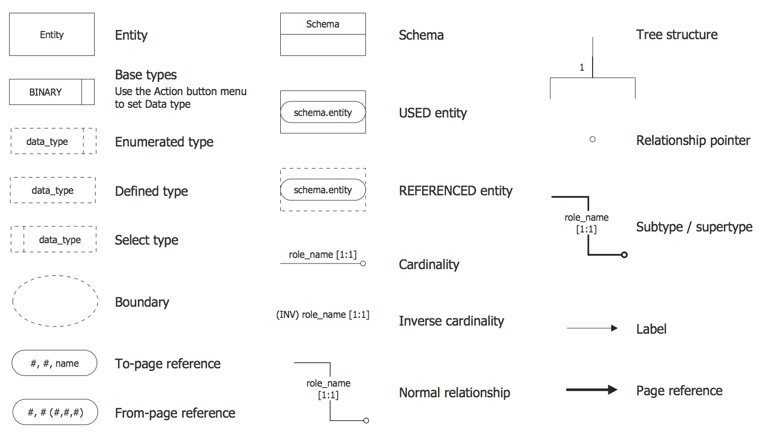
EXPRESS-G data Modeling Diagram solution extends the ConceptDraw DIAGRAM software functionality with capabilities of EXPRESS data modeling language allowing designing professional-looking EXPRESS-G diagrams, EXPRESS-G Data Modeling Diagrams and Database Model Diagrams with the help of included data modeling tools, Express-G diagram tool, database diagram tool, database design tool. It includes a wide variety of pre-made vector objects of EXPRESS-G notation including the entity, base types, enumerated type, defined type, select type, boundary, to-page reference, from-page reference, schema, used entity, referenced entity, cardinality, inverse cardinality, normal relationship, tree structure, relationship pointer, subtype / supertype, label, and page reference objects. This solution provides also the set of EXPRESS-G diagrams samples, which ideally suit to learn the principles of drawing similar diagrams and will be a perfect basis for software developers, software designers, software engineers and other stakeholders to make their data models for information systems, to develop the databases and to draw their own EXPRESS-G Data Modeling Diagrams, Express-G Diagrams or Database Model Diagram without any efforts.
-
Install this solution Free -
What I need to get started -
Solution Requirements - This solution requires the following products to be installed:
ConceptDraw DIAGRAM v18 - This solution requires the following products to be installed:
-
Compatibility - Sonoma (14), Sonoma (15)
MS Windows 10, 11 - Sonoma (14), Sonoma (15)
-
Support for this Solution -
Helpdesk
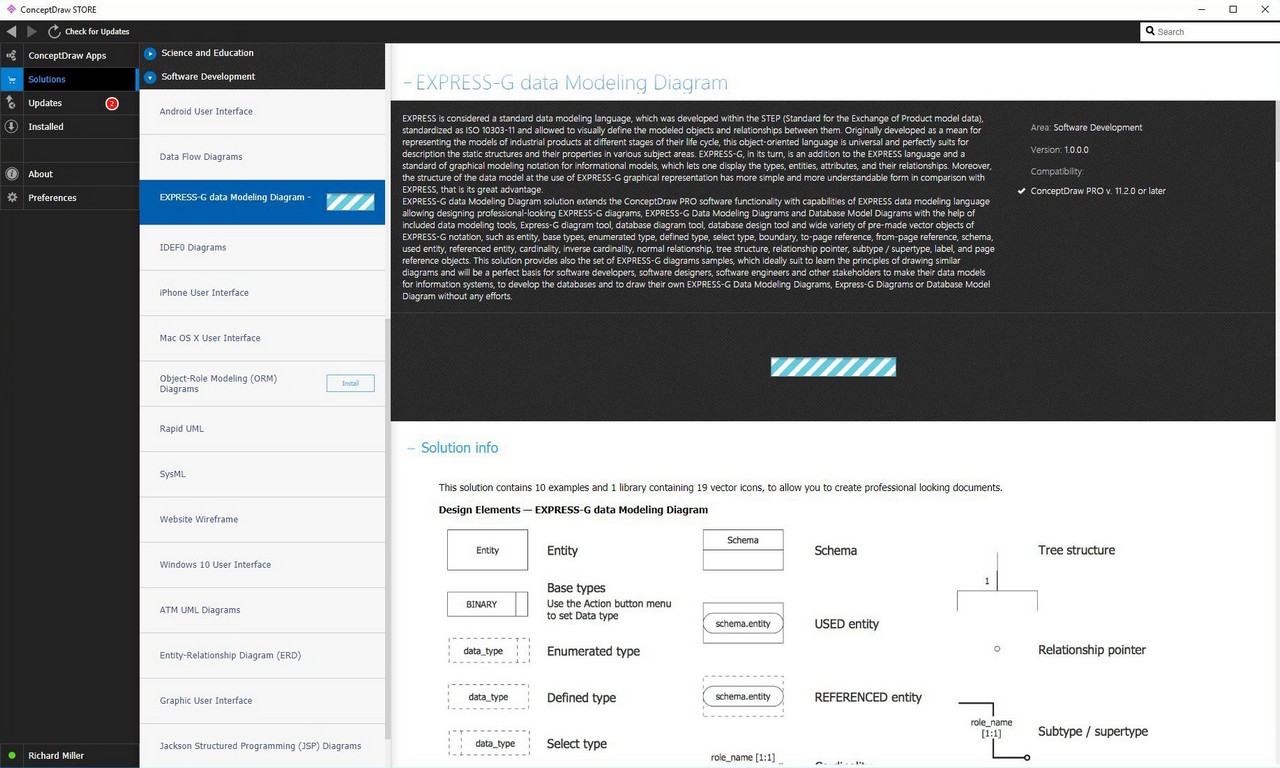
This solution contains 10 examples and 1 library containing 19 vector icons, to allow you to create professional looking documents.
Design Elements — EXPRESS-G data Modeling Diagram
Examples
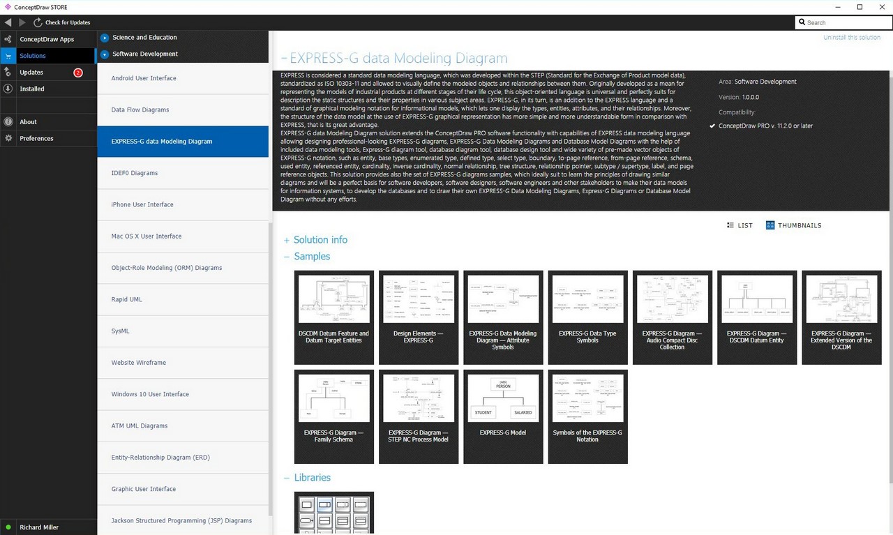
There are a few samples that you see on this page which were created in the ConceptDraw DIAGRAM application by using the EXPRESS-G data Modeling Diagram solution. Some of the solution's capabilities as well as the professional results which you can achieve are all demonstrated here on this page.
All source documents are vector graphic documents which are always available for modifying, reviewing and/or converting to many different formats, such as MS PowerPoint, PDF file, MS Visio, and many other graphic ones from the ConceptDraw Solution Park or ConceptDraw STORE. The EXPRESS-G data Modeling Diagram solution is available to all ConceptDraw DIAGRAM users to get installed and used while working in the ConceptDraw DIAGRAM diagramming and drawing software.
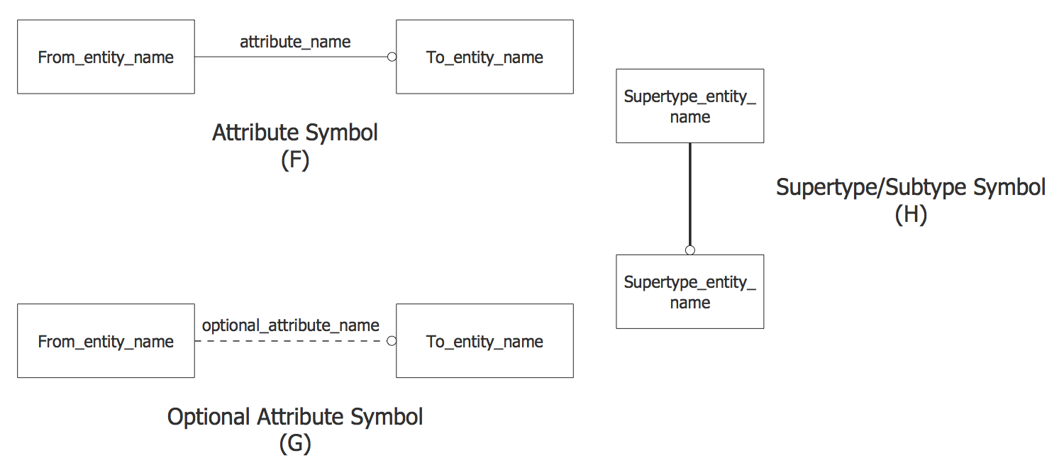
Example 1: EXPRESS-G Data Modeling Diagram — Attribute Symbols
This diagram was created in ConceptDraw DIAGRAM using the EXPRESS-G data Modeling Diagram library from EXPRESS-G data Modeling Diagram Solution. An experienced user spent 5 minutes creating this sample.
This example illustrates the attribute symbols of EXPRESS-G notation. The entity attributes are a way to specify the properties to the entities and to link the entities between each other according to the specific role. For specifying the role is used the name of the attribute. Some data types can serve as the type of an attribute. For each attribute can be specified one of the following three types: explicit (with direct values that are visible in a STEP-file), derived (that gets its value from an expression that refers to other attributes of this instance) or inverse (that adds the name and constrain an explicit attribute to an entity from the other end), which can be also re-declared in a subtype. As for the attribute of an explicit type, it can be re-declared as a derived in a subtype. Note that any other changes in kinds of attributes are impossible.
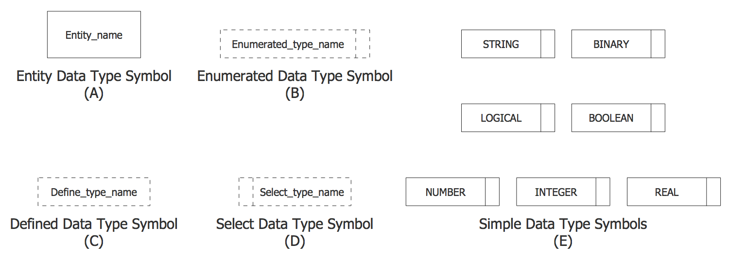
Example 2: EXPRESS-G Data Type Symbols
This diagram was created in ConceptDraw DIAGRAM using the EXPRESS-G data Modeling Diagram library from EXPRESS-G data Modeling Diagram Solution. An experienced user spent 5 minutes creating this sample.
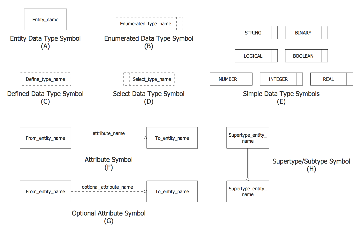
This diagram sample was drawn on the base of the Wikimedia Commons file and demonstrates the EXPRESS-G notation data type symbols. You can observe the large set of data types provided by EXPRESS-G notation and represented by specific data type symbols. These are Entity data type symbol, Enumeration Data Type symbol, Defined Data Type symbol, Select Data Type symbol, and extensive set of Simple Data Type symbols, which includes such symbols as String, Logical, Binary, Boolean, Number, Integer, and Real. All these symbols are represented at the EXPRESS-G library of ConceptDraw's EXPRESS-G solution from the Software Development area by specially developed vector design elements and are available for use when making the EXPRESS-G diagrams. Dragging the favorite elements, resizing them, arranging and connecting in a needed way, you can design professional-looking diagrams of any content, fullness and detalization you need, literally in a few minutes and without any efforts.
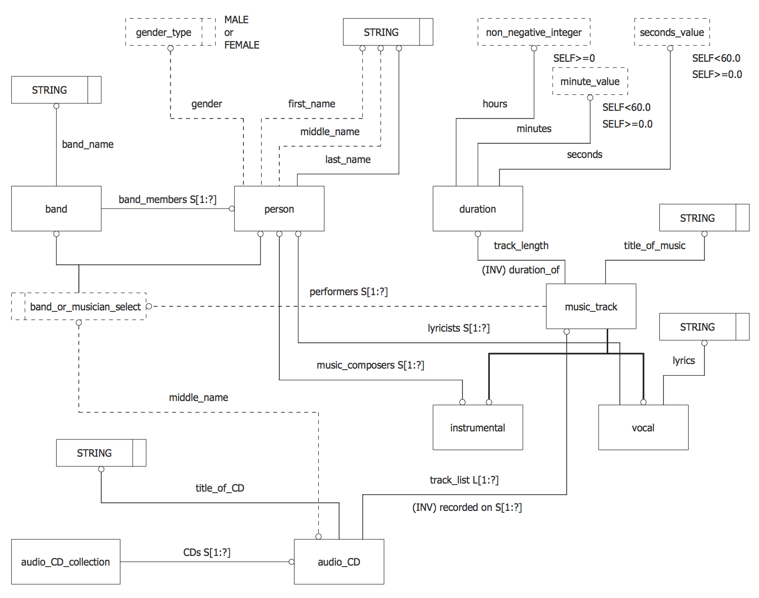
Example 3: EXPRESS-G Diagram — Audio Compact Disc Collection
This diagram was created in ConceptDraw DIAGRAM using the EXPRESS-G data Modeling Diagram library from EXPRESS-G data Modeling Diagram Solution. An experienced user spent 15 minutes creating this sample.
This EXPRESS-G diagram sample represents the data model, which was drawn on the base of Figure A.1 “EXPRESS-G model of an audio compact disc collection” from the Michael R. McCaleb’s article "A Conceptual Data Model of Datum Systems", which is an employee of the National Institute of Standards and Technology. This sample presented in EXPRESS-G notation using the notation symbols from ConceptDraw's EXPRESS-G data Modeling Diagram library lets one observe in a visual graphical view the requirements of a database for an audio compact disc (CD) collection. There are used the enumerated data type symbols in this diagram, which indicate that the values to be taken by attributes are limited by the values identified in the enumerated list or documented in EXPRESS models. Typically, these values are not depicted in the EXPRESS-G diagrams. As for this EXPRESS-G diagram, for more readability and visuality, all permissible values for a Gender type were annotated in the diagram.
Example 4: EXPRESS-G Diagram — DSCDM Datum Entity
This diagram was created in ConceptDraw DIAGRAM using the EXPRESS-G data Modeling Diagram library from EXPRESS-G data Modeling Diagram Solution. An experienced user spent 5 minutes creating this sample.
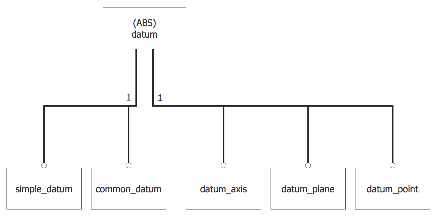
This sample represents the EXPRESS-G diagram showing a possible further specialization of the DSCDM (Datum System Conceptual Data Model) Datum entity. There are several ways in which the DSCDM can be specialized, this can be Specialization of Datum, Specialization of Datum_feature, Specialization of Datum_target, and some others. Depending on the application, the specializations can be required or not. The Datum entity can be refined to account such varied types of datum as the datum points, datum axes, and datum planes. This sample illustrates this specialization of the DSCDM Datum entity. Note also that some additional constraints associated with the Datum entity can exist. Only a few minutes were taken to create this EXPRESS-G diagram example using the pre-made objects from the EXPRESS-G data Modeling Diagram library from the self-titled solution, which only needed to be dragged, arranged and connected in a special way to display the main meaning of the diagram.
Example 5: DSCDM Datum Feature and Datum Target Entities
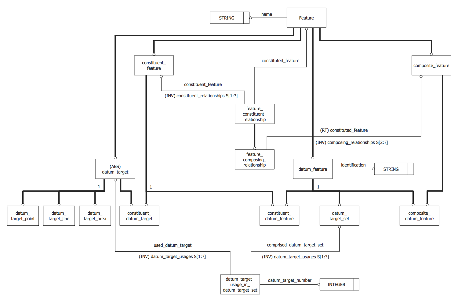
This diagram was created in ConceptDraw DIAGRAM using the EXPRESS-G data Modeling Diagram library from EXPRESS-G data Modeling Diagram Solution. An experienced user spent 10 minutes creating this sample.
This EXPRESS-G diagram sample is a data model example that shows the possible specializations of the Datum System Conceptual Data Model (DSCDM) Datum_feature and Datum_target entities. Designed in ConceptDraw DIAGRAM, it is based on the Figure C.3 from the article "A Conceptual Data Model of Datum Systems" issued by Michael R. McCaleb from the National Institute of Standards and Technology. Look at the diagram and find the Datum_target entity. It can be further specialized to account for the different types of the datum targets, such as the datum target lines, datum target points, and datum target areas, or to indicate when the datum target is a constituent of some another feature. Pay attention that additional constraints associated with the Datum_target entity also can be present. Because the datum targets are not completed features and moreover usually are constituents of other features, so the Datum_target entity not obligatory must be associated with a parent entity.
Example 6: EXPRESS-G Diagram — Extended Version of the DSCDM
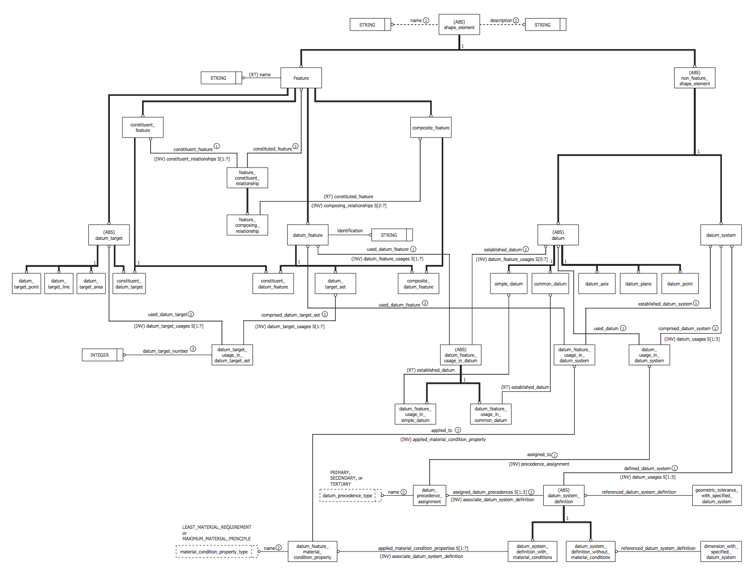
This diagram was created in ConceptDraw DIAGRAM using the EXPRESS-G data Modeling Diagram library from EXPRESS-G data Modeling Diagram Solution. An experienced user spent 20 minutes creating this sample.
This EXPRESS-G diagram example demonstrates an extended version of the Datum System Conceptual Data Model (DSCDM). First published as a Figure E.1 in "A Conceptual Data Model of Datum Systems" article of Michael R. McCaleb at the Journal of Research of the National Institute of Standards and Technology, this data model is now redrawn with the help of tools of ConceptDraw DIAGRAM software and EXPRESS-G data Modeling Diagram solution from Software Development area. It represents the DSCDM, which is useful for data exchange, includes the set of specializations of the DSCDM, as well as the Shape_element entity corresponding to the generic concept of the shape element, and Non_feature_shape_element entity corresponding to any shape element, which is not on the surface of a part. This diagram has an extensive structure but is perfectly drawn in ConceptDraw DIAGRAM, which is comfortable software for designing and navigation diagrams of any size and complexity.
Example 7: EXPRESS-G Diagram — Family Schema
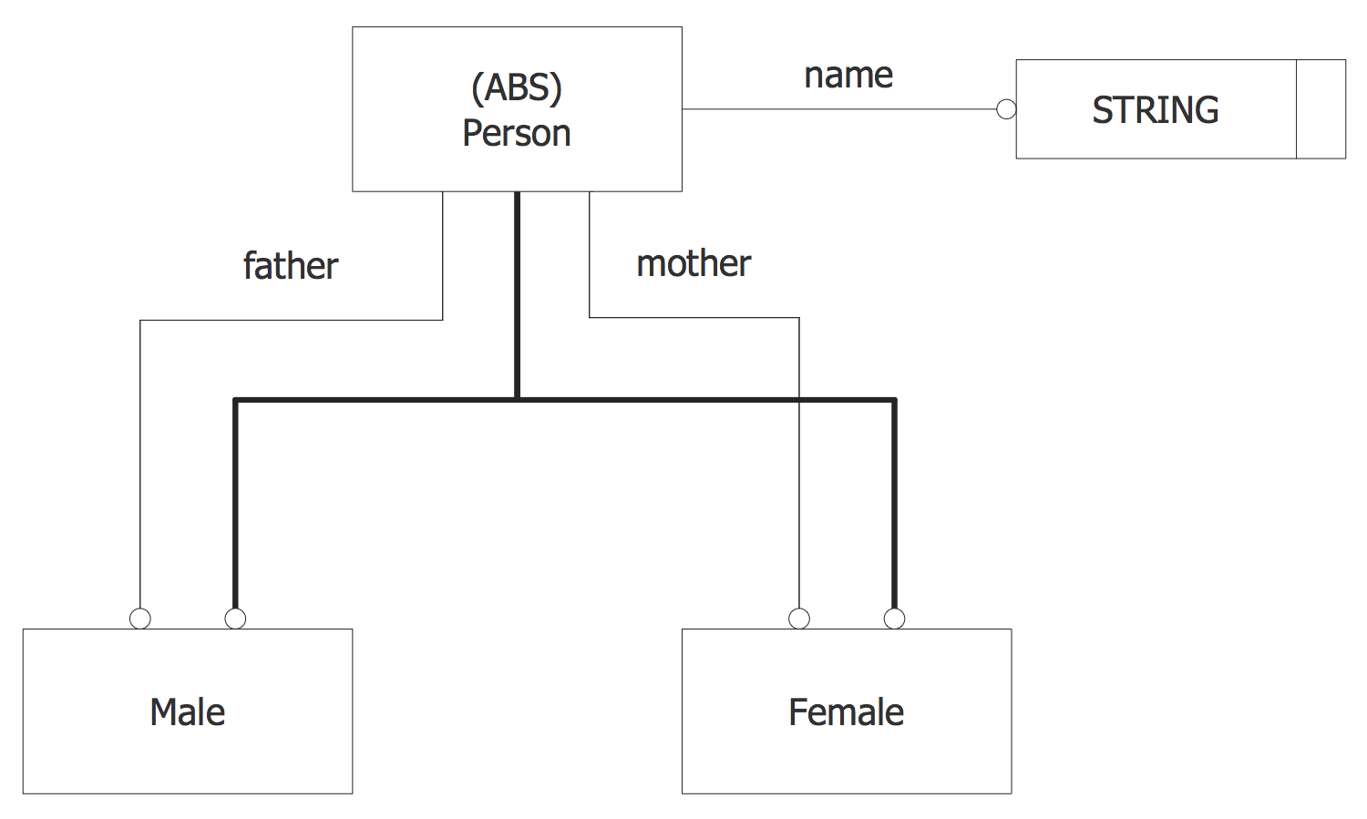
This diagram was created in ConceptDraw DIAGRAM using the EXPRESS-G data Modeling Diagram library from EXPRESS-G data Modeling Diagram Solution. An experienced user spent 5 minutes creating this sample.
This EXPRESS-G diagram sample is a data model that illustrates the family schema. You can observe the supertype entity Person in this diagram with two subtypes Male and Female. Moreover, the entity Person is declared as abstract (ABS), so only occurrences of Male and Female subtypes can exist. Each occurrence of a person obligatory has the name attribute and optional mother and father attributes. As for the reading this diagram and comprehension relations of attributes to the entities, it is defined a fixed style of reading the similar diagrams. So, the information from this diagram can be read unambiguously, one can read "a Male can play the role of father for a Person" and "a Female can play the role of mother for a Person". All notation shapes used in this diagram are commonly used in the charts of this type, thus are easily recognizable and comprehensible for all stakeholders.
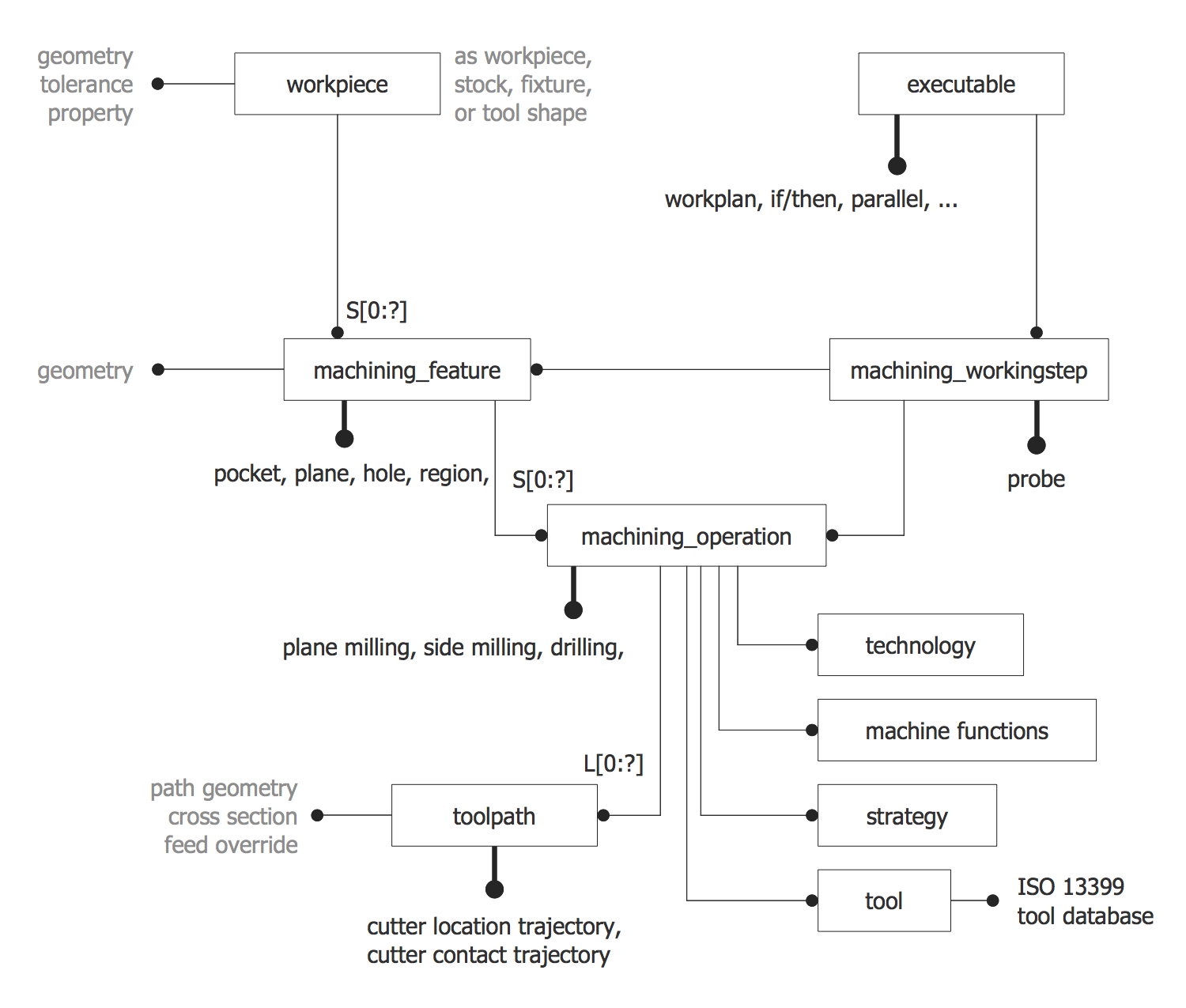
Example 8: EXPRESS-G Diagram — STEP NC Process Model
This diagram was created in ConceptDraw DIAGRAM using the EXPRESS-G data Modeling Diagram library from EXPRESS-G data Modeling Diagram Solution. An experienced user spent 10 minutes creating this sample.
This EXPRESS-G diagram sample depicts the STEP-NC process model, showing the major concepts and links to other additional information. STEP-NC is a machine tool control language and extension of ISO 10303 STEP standards with a machining model of ISO 14649. STEP-NC replaces ISO 6983 (DIN 66025) standard, which was developed many years ago and supporting only simple commands. Unlike ISO 6983, the STEP-NC (ISO 14 649) supposes two-way exchange of information CAM-NC-levels, adds the STEP PDM model for integration into a wider enterprise, provides modern associative communications protocol allowing to connect the CNC (computer numerical controlled) process data to a product description and sets a number of functionality components of UOF (Units of Functionality), such as: project, workpiece, feature, executable, operation, toolpath, measures. Relations between the components are shown and described in this diagram with the help of graphical notation of EXPRESS object-oriented language, which is useful for description all STEP application protocols.
Example 9: EXPRESS-G Model
This diagram was created in ConceptDraw DIAGRAM using the EXPRESS-G data Modeling Diagram library from EXPRESS-G data Modeling Diagram Solution. An experienced user spent 5 minutes creating this sample.
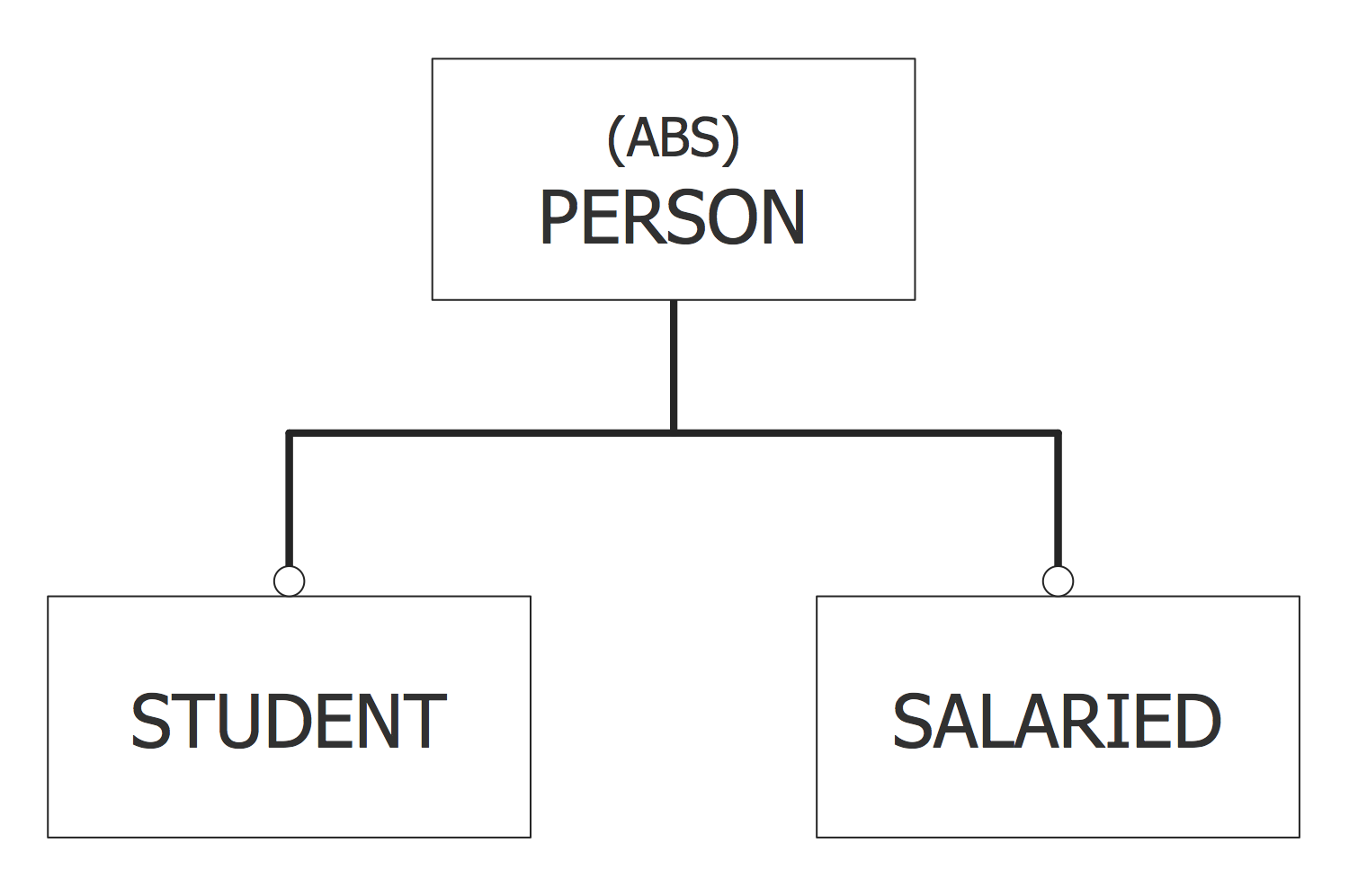
This sample demonstrates a simple EXPRESS-G model designed using the EXPRESS-G graphical notation standard for informational models. EXPRESS-G is an addition to the EXPRESS data modeling language, which provides the special graphical notation and lets clearly present the unambiguous data. The EXPRESS model can be represented in a graphical or textual form, but the graphical form such as used in this diagram lets clearly depict the entities, links, other elements and their types, and easier the comprehension and perception of diagrams that are convenient for using when designing tutorials, materials for lectures and speeches, explanation materials, and other documents. However, additional information and details for these diagrams can be outlined in a textual form near the graphical representation. This diagram defines and represents an abstract supertype entity Person and two subtype entities Student and Salaried, which are related to a Person entity. Use the ConceptDraw’s EXPRESS-G data Modeling Diagram solution to design both simple and complex EXPRESS-G diagrams fast and easy.
Example 10: Symbols of the EXPRESS-G Notation
This diagram was created in ConceptDraw DIAGRAM using the EXPRESS-G data Modeling Diagram library from EXPRESS-G data Modeling Diagram Solution. An experienced user spent 10 minutes creating this sample.
This diagram sample illustrates all variety of EXPRESS-G notation symbols, which are generally accepted and intended for use when making EXPRESS-G diagrams. EXPRESS-G defines the series of datatypes with the help of specific data type symbols of EXPRESS-G notation that you can see here. You can find the graphical symbols for the Entity Data Type, Enumerated Data Type, Defined Data Type, Select Data Type, Simple Data Types, Attribute, Optional Attribute and Supertype / Subtype. All these symbols are represented by ConceptDraw’s vector design objects available for use from the EXPRESS-G data Modeling Diagram library included to EXPRESS-G data Modeling Diagram solution from Software Development area of ConceptDraw Solution Park. To make your own data model and to design EXPRESS-G diagram for its graphical representation, step by step drag the needed notation objects from the library to your document and compose the desired combination from them, not forgetting to establish links between the elements.
Inside
What I Need to Get Started
Both ConceptDraw DIAGRAM diagramming and drawing software and the EXPRESS-G data Modeling Diagram solution can help creating the software engineering diagrams you need. The EXPRESS-G data Modeling Diagram solution can be found in the Software Development area of ConceptDraw STORE application that can be downloaded from this site. Make sure that both ConceptDraw DIAGRAM and ConceptDraw STORE applications are installed on your computer before you get started.
How to install
After ConceptDraw STORE and ConceptDraw DIAGRAM are downloaded and installed, you can install the EXPRESS-G data Modeling Diagram solution from the ConceptDraw STORE.
Start Using
To make sure that you are doing it all right, use the pre-designed symbols from the stencil libraries from the solution to make your drawings look smart and professional. Also, the pre-made examples from this solution can be used as drafts so your own drawings can be based on them. Using the samples, you can always change their structures, colors and data.
EXPRESS-G data Modeling Diagram
The Express-G Data Modeling Diagrams solution includes the graphical symbols and pre-made examples of the diagrams. It can be always used while creating the unique and professional looking EXPRESS-G Data Modeling Diagrams in the ConceptDraw DIAGRAM diagramming and vector drawing software.
Data modeling is the process of creating the data model for the information system in software engineering. EXPRESS is an international standard data modeling language. EXPRESS is formalized in the ISO 10303 Standard for the Exchange of Product model STEP (Standard for the Exchange of Product model data). EXPRESS data models may formally define data objects as well as the relationships among them.
The application of EXPRESS data models is supporting the databases’ development enabling the exchange of data for a domain of interest. Any EXPRESS data model can be defined in either a graphical or in a textual way.
The graphical representation can be more suitable for human use. The examples of the fields of its application may be tutorials or visual explanation in a way of a drawing. The graphical representation is called as “EXPRESS-G”. The major feature of EXPRESS itself is the possibility of checking for the structural and algorithmic rules.

Pic. 1. EXPRESS-G Diagram
EXPRESS-G is a formal graphical notation for the display of data specifications. Such specifications are defined in the so-called “EXPRESS language”. This notation supports a subset of the EXPRESS language.
EXPRESS-G supports different levels of data abstraction, diagrams that span more than one page as well as those which use minimal computer graphics capabilities.
EXPRESS-G helps to display both type and entity definitions, cardinality and relationships. One of the advantages of using EXPRESS-G is that the structure of a data model can be presented in a simple and easy-to-understand manner. There are also a few disadvantages, such as the fact that complex constraints can never be formally specified.
EXPRESS-G model is a form of a diagram consisting of the graphic symbols. Three types of graphic symbols are included in EXPRESS-G notation. The first type is definition. It includes the symbols that denote some simple data types as well as the named data types constructed EXPRESS schema declarations and data types. Next type is relationship. It includes symbols that describe relationships between the definitions. And the third type is composition. A composition includes symbols that enable a diagram to be displayed on more than one page.
The definitions of schemas and data types are denoted by boxes within a diagram. These boxes enclose the name of the item that is being defined. The relationships between the items are always denoted with the help of the lines that join the boxes. Differing the line styles may provide the information on the kind of relationship or definition.
A relationship for an optional attribute of an entity data type can be presented within a data modeling diagram as a dashed line, same as the schema reference. An inheritance relationship, such as a sub-type or a sub-type relationship, is presented with the aid of a thick line, while all other normal relationships are illustrated with the help of solid lines. For an inheritance relationship type, though, the representation is expressed with a circle at the subtype end of this line.
Any EXPRESS-G symbols may be used for representing the definitions as well as their relationships within one schema. The components of a single schema diagram are usual data types, entity data types, relationship symbols and defined data types.
Schema level diagrams consist of the representation of different schemas as well as their interfaces.
The contents of any EXPRESS-G schema level diagram are limited. A relationship line of a normal width presents the USE interface. Such interface may be represented from the using schema to the used schema, having an open circle denoting the used schema.
The dashed lines that represent the relationships show the REFERENCE interface from the referencing schema, having an open circle denoting the referenced schema. Once a schema level diagram extends for over one page having the schema interfaces crossing the page boundaries, the page referencing symbols can be usually used.
A so-called “complete diagram” in EXPRESS-G represents all the definitions, constraints and relationships within the limits of the EXPRESS-G notation by using either a schema level diagram or an entity level. Using the pre-made examples from the EXPRESS-G Data Modeling Diagrams solution can assist in creating the unique drawings within only a couple of minutes. Once there is the EXPRESS-G Data Modeling Diagrams solution by a team of professionals, then any ConceptDraw DIAGRAM user may rely upon it as it includes all the needed tools such as the previously created drawings and a stencil library with 19 vector elements.
Having such templates as the “EXPRESS-G Data Modeling Diagram — Attribute Symbols”, “EXPRESS-G Data Type Symbols”, “EXPRESS-G Diagram — Audio Compact Disc Collection”, “EXPRESS-G Diagram — DSCDM Datum Entity”, “DSCDM Datum Feature and Datum Target Entities”, “EXPRESS-G Diagram — Extended Version of the DSCDM”, “EXPRESS-G Diagram — Family Schema”, “EXPRESS-G Diagram — STEP NC Process Model”, “EXPRESS-G Model” and the “Symbols of the EXPRESS-G Notation” can help with getting the professionally looking result once the work of drawing based on them is completed.
The EXPRESS-G Data Modeling Diagrams solution includes vector stencils libraries, Express-G diagram samples and templates and learning media for studying the best practices of diagramming using the ConceptDraw DIAGRAM software. To simplify creating the EXPRESS-G Diagrams use ConceptDraw DIAGRAM software with its extension the EXPRESS-G Data Modeling Diagrams solution from the Software Development area of ConceptDraw Solution Park.