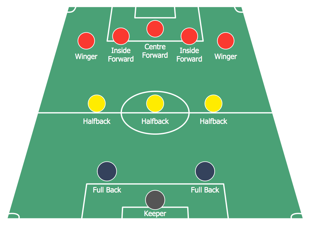
"In association football, the formation describes how the players in a team are positioned on the pitch. Different formations can be used depending on whether a team wishes to play more attacking or defensive football. ...
4–4–2.
This formation was the most common in football in the 1990s and early 2000s, so well known that it has even inspired a magazine title, FourFourTwo. The midfielders are required to work hard to support both the defence and the attack: typically one of the central midfielders is expected to go upfield as often as possible to support the forward pair, while the other will play a "holding role", shielding the defence; the two wide midfield players must move up the flanks to the goal line in attacks and yet also protect the fullback wide defenders." [Formation (association football). Wikipedia]
The diagram example "Association football (soccer) formation 4-4-2" was created using the ConceptDraw PRO diagramming and vector drawing software extended with the Football solution from the Sport area of ConceptDraw Solution Park.
www.conceptdraw.com/ solution-park/ sport-soccer
Soccer (Football) Formation
Using diagrams is the easiest way to explain the soccer formations. The Soccer solution from the Sport area of ConceptDraw Solution Park is designed as a tool that helps you produce the soccer diagrams in a few minutes. The predesigned samples of the Soccer solution for ConceptDraw PRO depict the most popular formation diagrams."In association football, the formation describes how the players in a team are positioned on the pitch. Different formations can be used depending on whether a team wishes to play more attacking or defensive football. ...
4–4–1–1.
A variation of 4–4–2 with one of the strikers playing "in the hole", or as a "second striker", slightly behind their partner. The second striker is generally a more creative player, the playmaker, who can drop into midfield to pick up the ball before running with it or passing to teammates.
Interpretations of 4–4–1–1 can be slightly muddled, as some might say that the extent to which a forward has dropped off and separated himself from the other can be debated." [Formation (association football). Wikipedia]
The diagram example "Association football (soccer) formation 4-4-1-1" was created using the ConceptDraw PRO diagramming and vector drawing software extended with the Football solution from the Sport area of ConceptDraw Solution Park.
www.conceptdraw.com/ solution-park/ sport-soccer
"In association football, the formation describes how the players in a team are positioned on the pitch. Different formations can be used depending on whether a team wishes to play more attacking or defensive football. ...
The 4–3–3 was a development of the 4–2–4, and was played by the Brazilian national team in the 1962 World Cup. The extra player in midfield allows a stronger defence, and the midfield could be staggered for different effects. The three midfielders normally play closely together to protect the defence, and move laterally across the field as a coordinated unit. The three forwards split across the field to spread the attack, and may be expected to mark the opposition full-backs as opposed to doubling back to assist their own full-backs, as do the wide midfielders in a 4–4–2. When used from the start of a game, this formation is widely regarded as encouraging expansive play, and should not be confused with the practice of modifying a 4–4–2 by bringing on an extra forward to replace a midfield player when behind in the latter stages of a game. This formation is suited for a short passing game and useful for ball retention.
A staggered 4–3–3 involving a defensive midfielder (usually numbered four or six) and two attacking midfielders (numbered eight and ten) was commonplace in Italy, Argentina, and Uruguay during the 1960s and 1970s. The Italian variety of 4–3–3 was simply a modification of WM, by converting one of the two wing-halves to a libero (sweeper), whereas the Argentine and Uruguayan formations were derived from 2–3–5 and retained the notional attacking centre-half. The national team which made this famous was the Dutch team of the 1974 and 1978 World Cups, even though the team won neither." [Formation (association football). Wikipedia]
The diagram example "Association football (soccer) formation 4-3-3" was created using the ConceptDraw PRO diagramming and vector drawing software extended with the Football solution from the Sport area of ConceptDraw Solution Park.
www.conceptdraw.com/ solution-park/ sport-soccer
 Soccer
The Soccer (Football) Solution extends ConceptDraw PRO v9.5 (or later) software with samples, templates, and libraries of vector objects for drawing soccer (football) diagrams, plays schemas, and illustrations. It can be used to make professional looking
Defensive Formation – 4-3 Defense Diagram
Using diagrams is the easiest way to explain American Football defensive formations. The Football solution for ConceptDraw PRO contains a set of samples depicts the most popular defensive formations diagrams. Using embedded presentation tools you are able to share your football knowledge with wide audience."In association football, the formation describes how the players in a team are positioned on the pitch. Different formations can be used depending on whether a team wishes to play more attacking or defensive football. ...
The WM system was created in the mid-1920s by Herbert Chapman of Arsenal to counter a change in the offside law in 1925. The change had reduced the number of opposition players that attackers needed between themselves and the goal-line from three to two. This led to the introduction of a centre-back to stop the opposing centre-forward, and tried to balance defensive and offensive playing. The formation became so successful that by the late-1930s most English clubs had adopted the WM. Retrospectively, the WM has either been described as a 3–2–5 or as a 3–4–3, or more precisely a 3–2–2–3 reflecting the letters which symbolised it. The gap in the centre of the formation between the two wing halves and the two inside forwards allowed Arsenal to counter-attack effectively. The W-M was subsequently adapted by several English sides, but none could apply it in quite the same way Chapman had. This was mainly due to the comparative rarity of Alex James in the English game. He was one of the earliest playmakers in the history of the game, and the hub around which Chapman's Arsenal revolved." [Formation (association football). Wikipedia]
The diagram example "Association football (soccer) formation 3-2-5 (WM)" was created using the ConceptDraw PRO diagramming and vector drawing software extended with the Football solution from the Sport area of ConceptDraw Solution Park.
www.conceptdraw.com/ solution-park/ sport-soccer
Goal Line Formation (Offense/Defense) Diagram
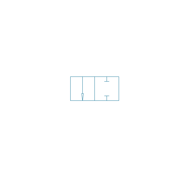
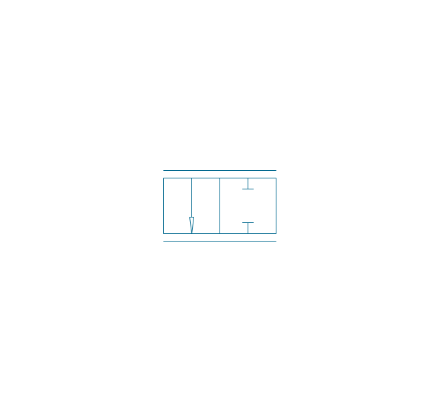
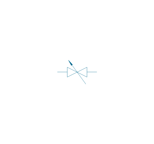
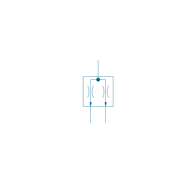
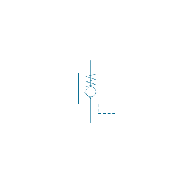
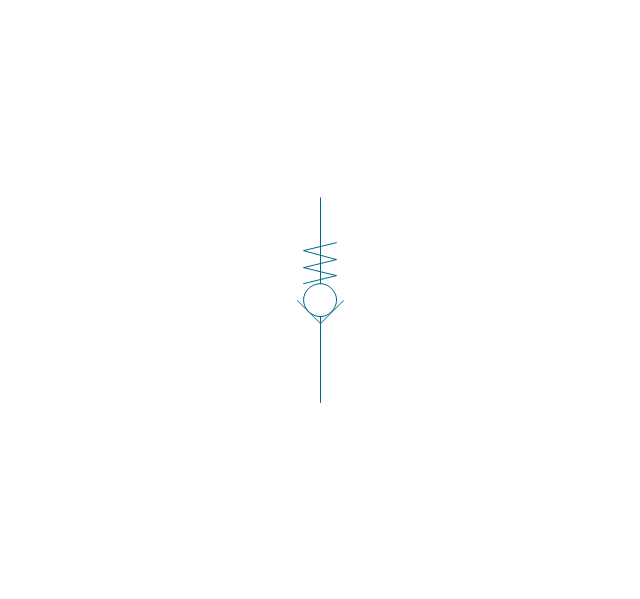
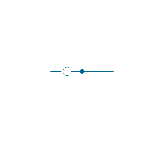
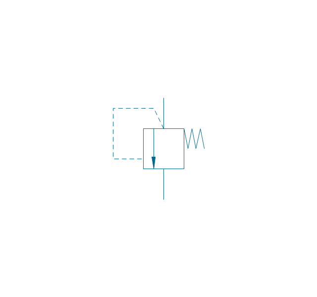
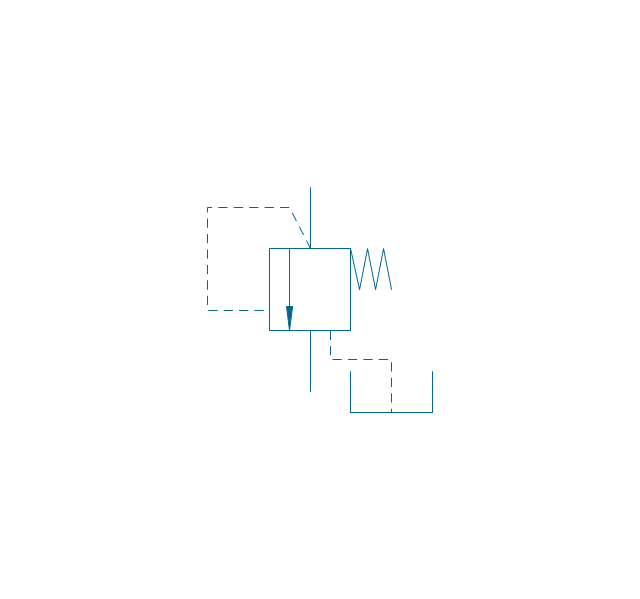
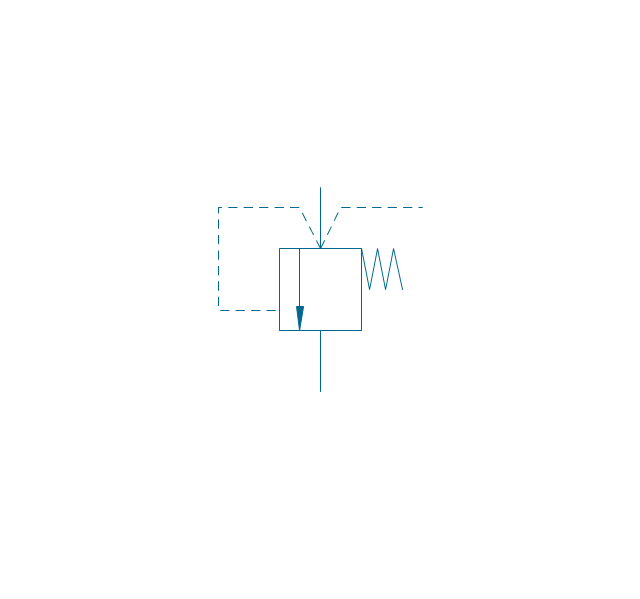
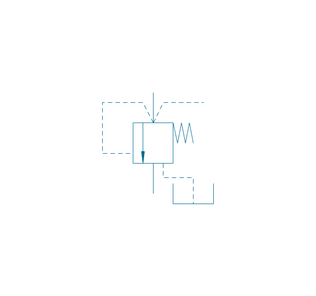
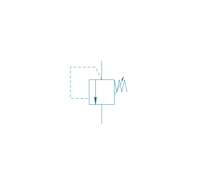
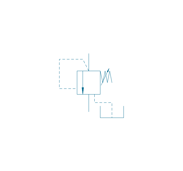
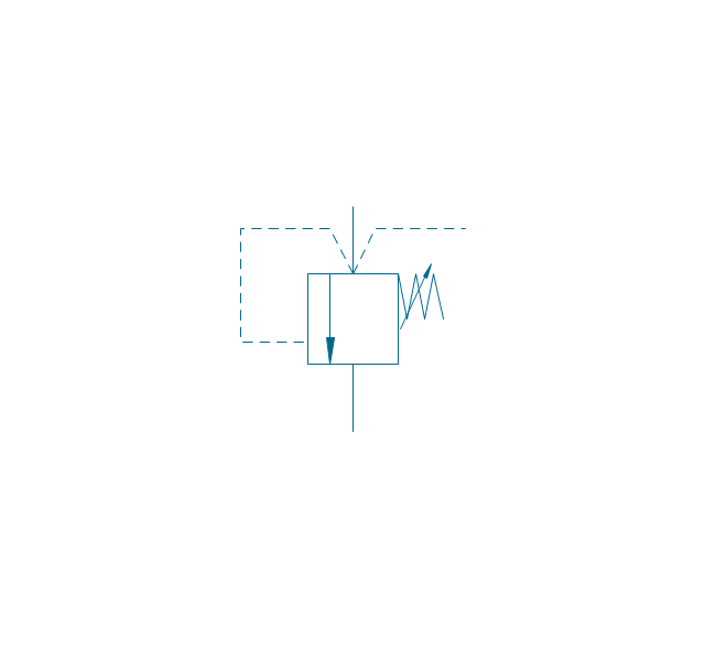
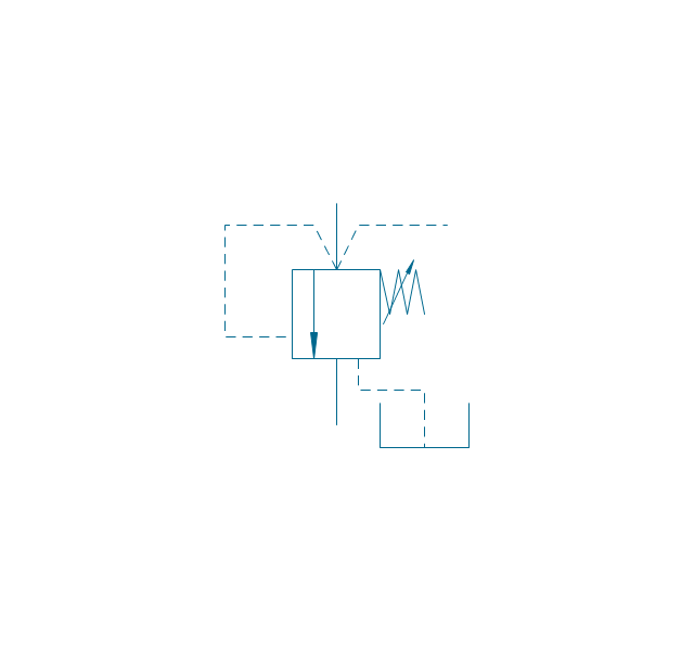
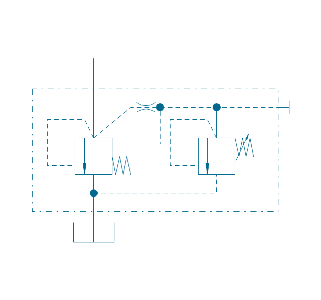
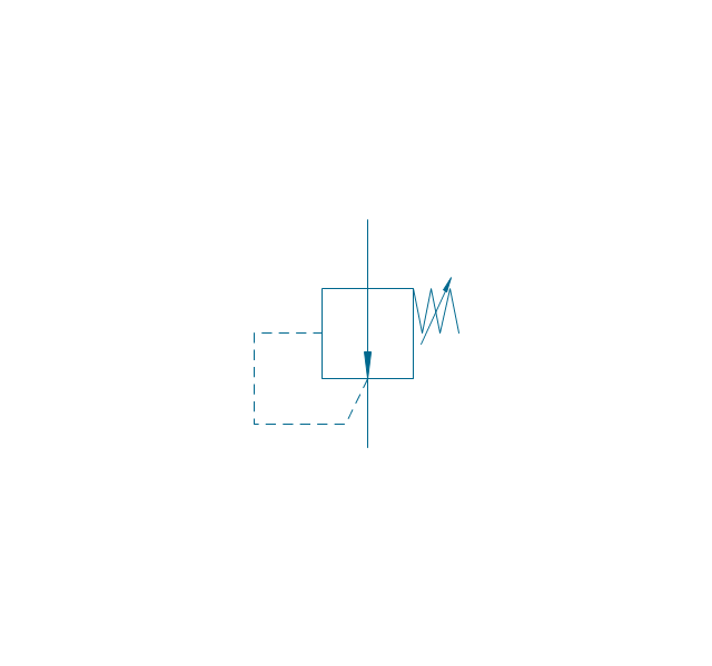
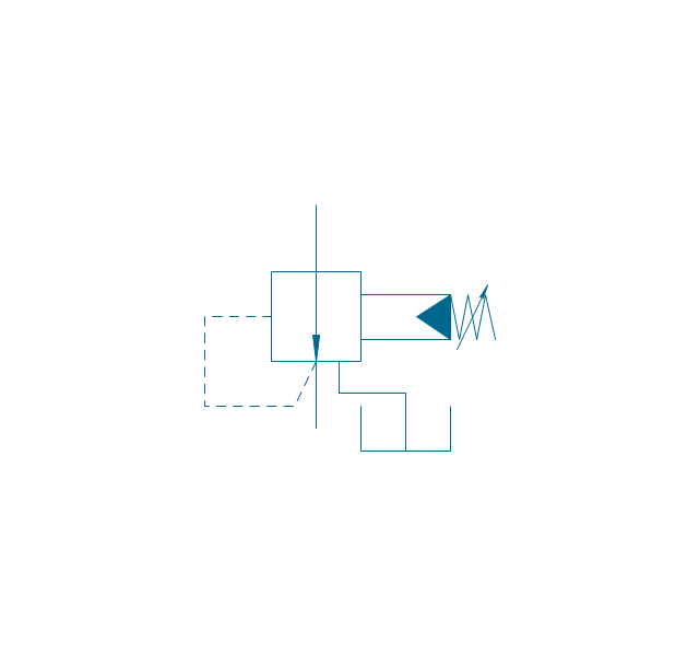
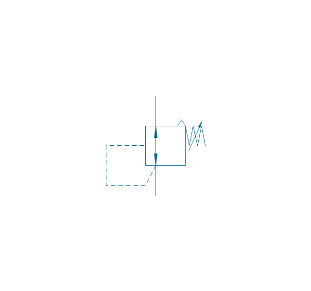
ConceptDraw PRO software extended with the Football solution delivers libraries, templates and samples allowing football fans or specialists to draw football-related schemas in minutes. A complete set of predesigned fields and positions make drawing schemas as quickly as possible.The vector stencils library "Fluid power valves" contains 93 symbols of pre-made hydraulic and pneumatic valves, including directional control valves, flow control valves, pressure control valves, and electrohydraulic and electropneumatic valves.
Use these shapes to design fluid power diagrams in the ConceptDraw PRO diagramming and vector drawing software extended with the Mechanical Engineering solution from the Engineering area of ConceptDraw Solution Park.
www.conceptdraw.com/ solution-park/ engineering-mechanical
Use these shapes to design fluid power diagrams in the ConceptDraw PRO diagramming and vector drawing software extended with the Mechanical Engineering solution from the Engineering area of ConceptDraw Solution Park.
www.conceptdraw.com/ solution-park/ engineering-mechanical
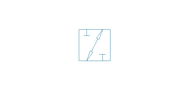
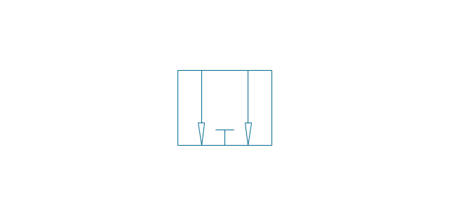
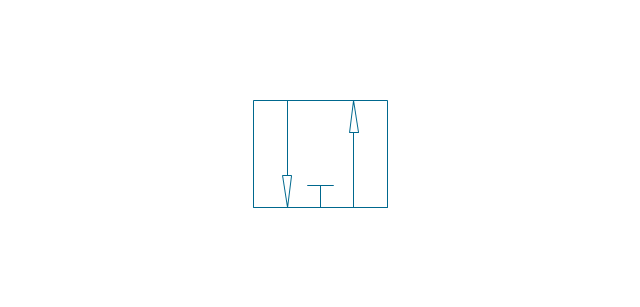
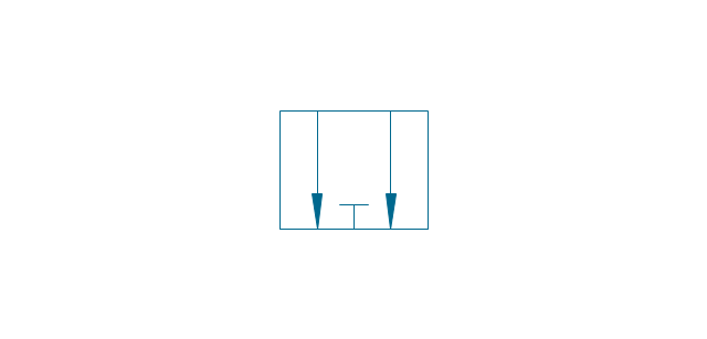
The vector stencils library "Fluid power valves" contains 93 symbols of pre-made hydraulic and pneumatic valves, including directional control valves, flow control valves, pressure control valves, and electrohydraulic and electropneumatic valves.
Use these shapes to design fluid power diagrams in the ConceptDraw PRO diagramming and vector drawing software extended with the Mechanical Engineering solution from the Engineering area of ConceptDraw Solution Park.
www.conceptdraw.com/ solution-park/ engineering-mechanical
Use these shapes to design fluid power diagrams in the ConceptDraw PRO diagramming and vector drawing software extended with the Mechanical Engineering solution from the Engineering area of ConceptDraw Solution Park.
www.conceptdraw.com/ solution-park/ engineering-mechanical
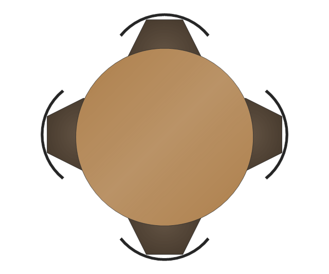
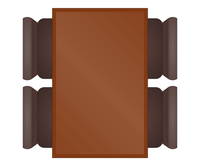
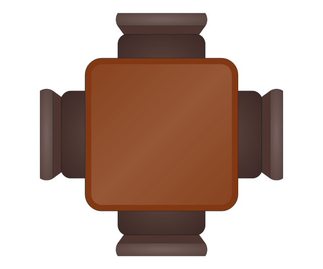
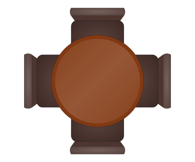
The vector stencils library "Cafe and restaurant" contains shapes of furniture and equipment.
Use these shapes for drawing cafe and restaurant design plans, arrangement and layouts in the ConceptDraw PRO diagramming and vector drawing software extended with the Cafe and Restaurant solution from the Building Plans area of ConceptDraw Solution Park. www.conceptdraw.com/ solution-park/ building-cafe-restaurant-plans
Use these shapes for drawing cafe and restaurant design plans, arrangement and layouts in the ConceptDraw PRO diagramming and vector drawing software extended with the Cafe and Restaurant solution from the Building Plans area of ConceptDraw Solution Park. www.conceptdraw.com/ solution-park/ building-cafe-restaurant-plans
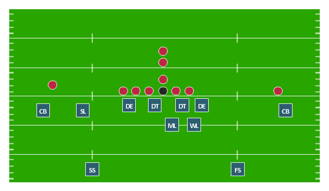
"In American football, a 4–3 defense is a defensive alignment consisting of four down linemen and three linebackers. It is probably the most commonly used defense in modern American football and especially in the National Football League. ...
In the original version of the 4–3, the tackles lined up over the offensive guards and the ends lined up on the outside shoulder of the offensive tackles, with the middle linebacker over the center and the other linebackers outside the ends. In the mid-1960s Hank Stram developed a popular variation, the "Kansas City Stack", which shifted the strong side defensive end over the tight end, stacked the strongside linebacker over the tackle, and shifted the weakside tackle over center. At about the same time the Cleveland Browns frequently used a weakside shift. The Dallas Cowboys coach Tom Landry developed a "flex" variation, in order to take advantage of the quickness of his Hall of Fame tackle, Bob Lilly. In Tom Landry's original 4–3 defenses (4-3 Inside and 4-3 Outside), both defensive tackle were flexed. In the "flex", on a pro set right, with defensive keys showing a run to the right, the right defensive tackle would be flush on the line and was supposed to penetrate. The right defensive end and left defensive tackle were flexed two feet off the line of scrimmage, the right defensive end now head on with the left offensive tackle (i.e. a 4-2-2-5 front instead of the more common 5-2-2-5 front). This gave the defense a "zig zag" look unlike any other of its day. More modern versions of the 4-3 include the Tampa 2 scheme and the 4-3 slide." [4–3 defense. Wikipedia]
The American football positions diagram example "Defensive play - Under front" was created using the ConceptDraw PRO diagramming and vector drawing software extended with the Football solution from the Sport area of ConceptDraw Solution Park.
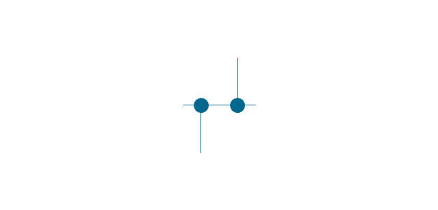
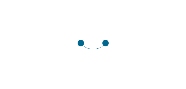
The vector stencils library "Transmission paths" contains 43 symbols of power transmission paths, electronic circuits, bus connectors and elbows, terminals, junctions, and concentrators.
Use it to annotate electrical diagrams, electronic schematics and circuit diagrams in the ConceptDraw PRO diagramming and vector drawing software extended with the Electrical Engineering solution from the Engineering area of ConceptDraw Solution Park.
www.conceptdraw.com/ solution-park/ engineering-electrical
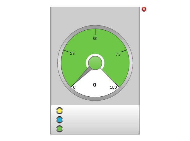
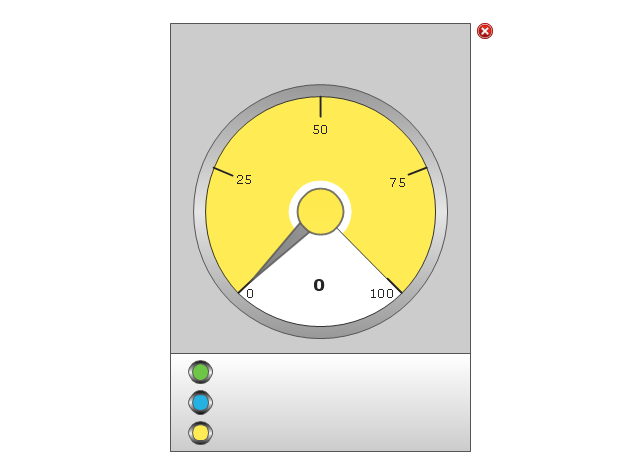
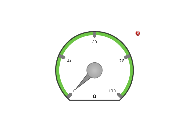
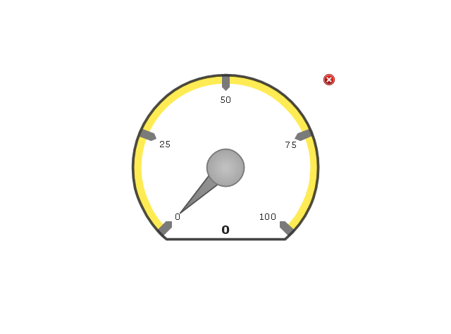
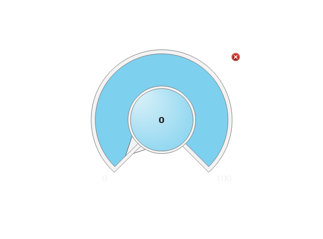
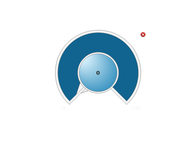
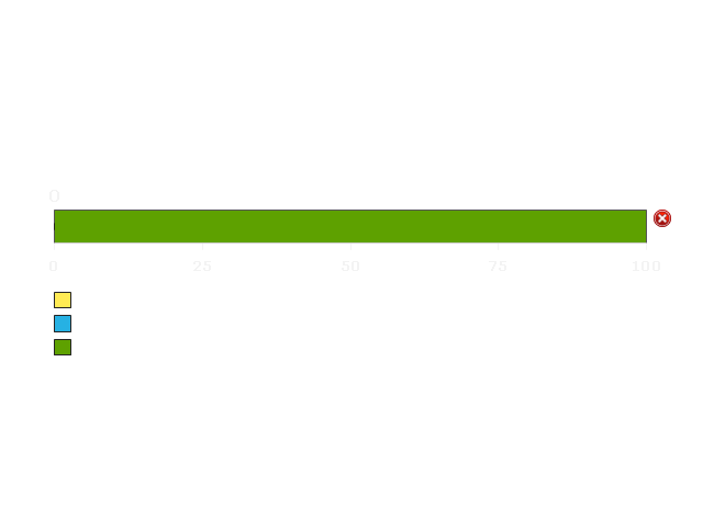
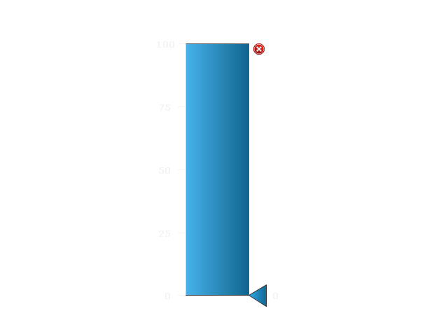
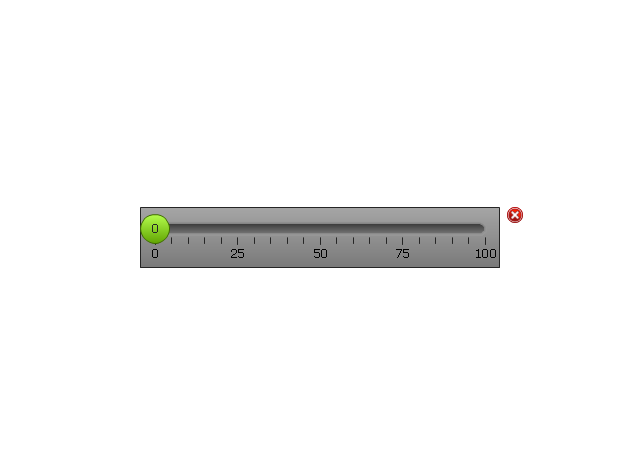
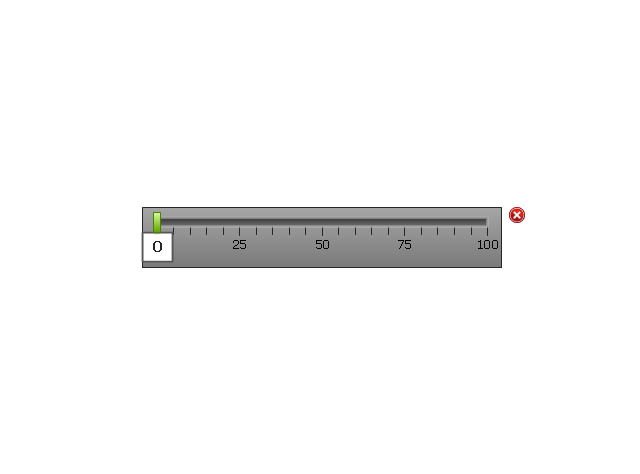
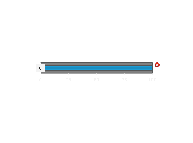
The vector stencils library "Meter indicators 2" (for dark background) contains 29 Live Objects: speedometer gauge, dial, bullet, slider and level meter visual indicators.
The Live Objects designed to display actual measures of performance metrics from external data source files. Some of them also display comparative measures, and colored zones of qualitative ranges with legend.
Use this library to create visual dashboards in the ConceptDraw PRO diagramming and vector drawing software extended with the Meter Dashboard solution from the area "What is a Dashboard" of ConceptDraw Solution Park.
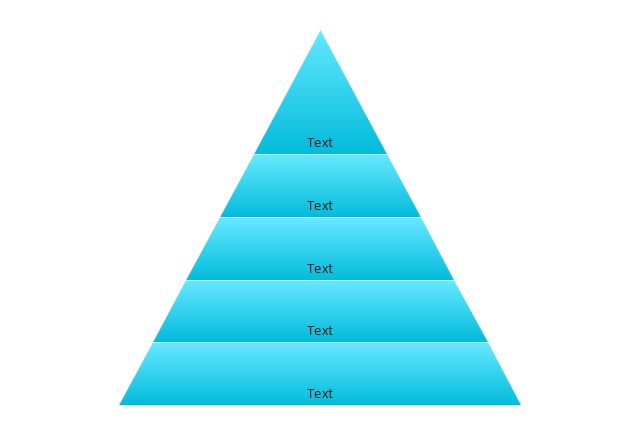
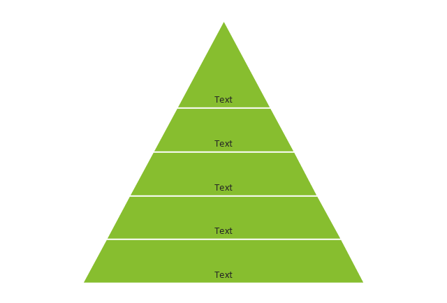
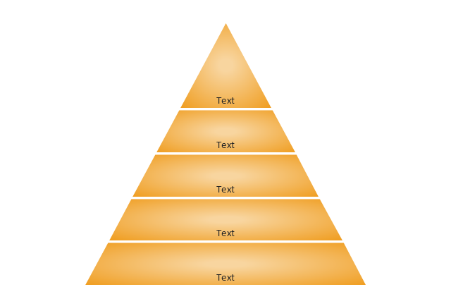
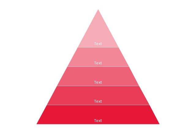
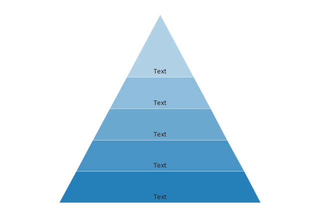
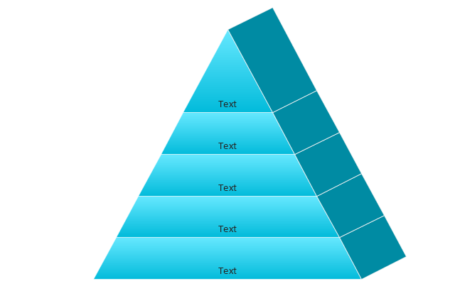
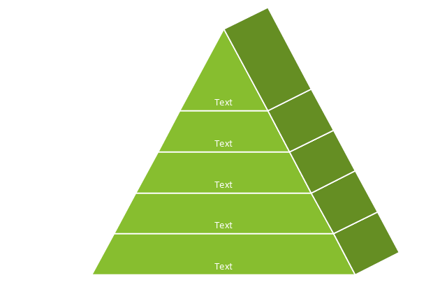
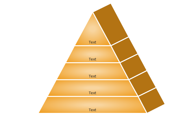
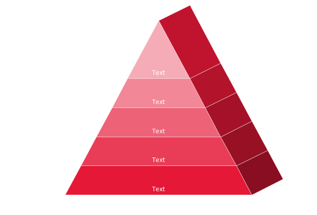
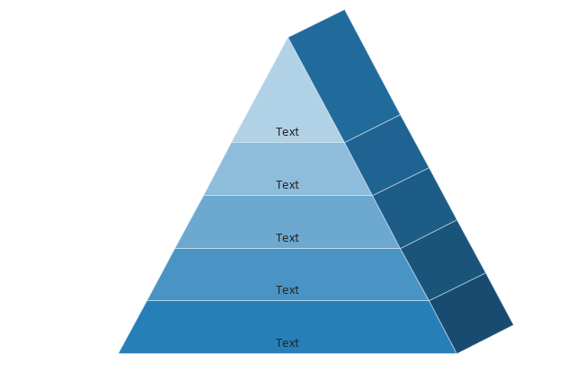
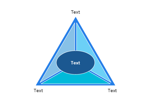
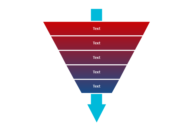
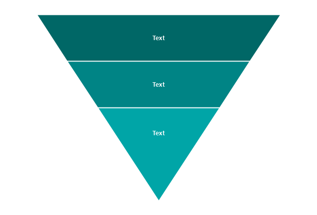
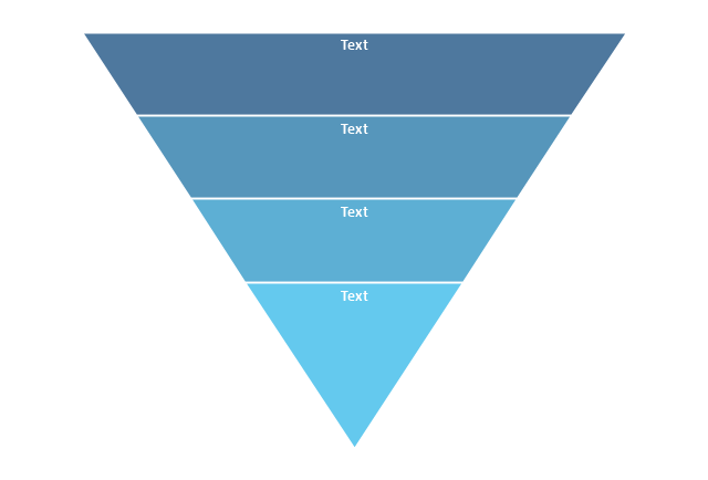
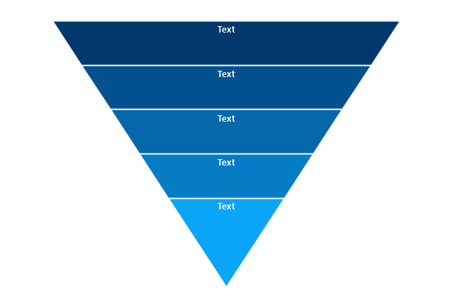
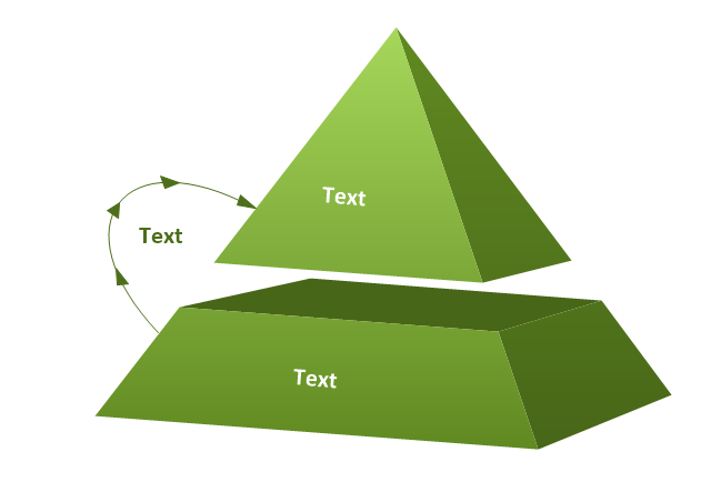
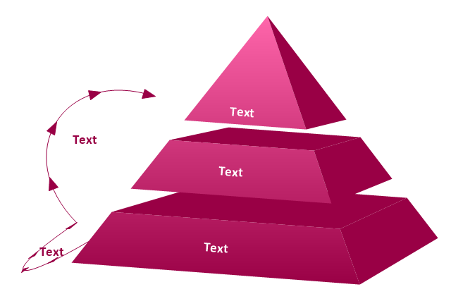
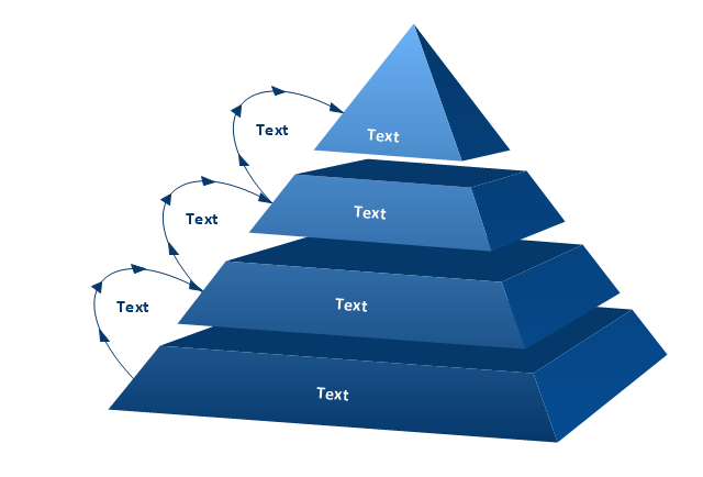
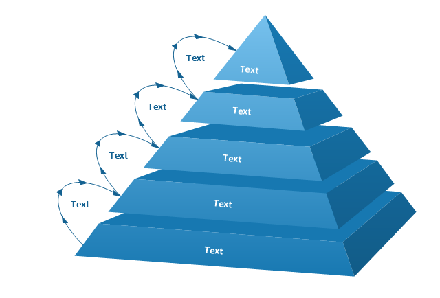
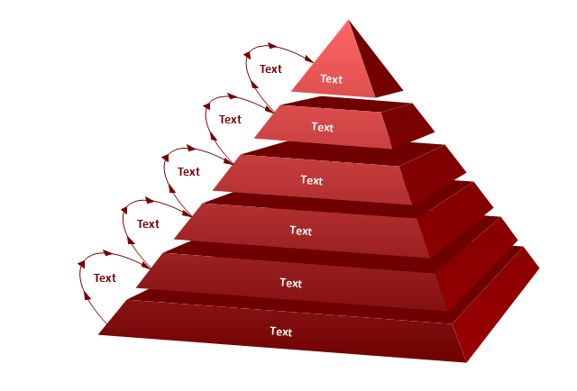
The vector stencils library "Pyramid diagrams" contains 28 templates of pyramid diagrams, triangle charts and triangular schemes.
Use these templates to create your pyramid diagrams in the ConceptDraw PRO diagramming and vector drawing software extended with the Pyramid Diagrams solution from the Marketing area of ConceptDraw Solution Park.
Use these templates to create your pyramid diagrams in the ConceptDraw PRO diagramming and vector drawing software extended with the Pyramid Diagrams solution from the Marketing area of ConceptDraw Solution Park.
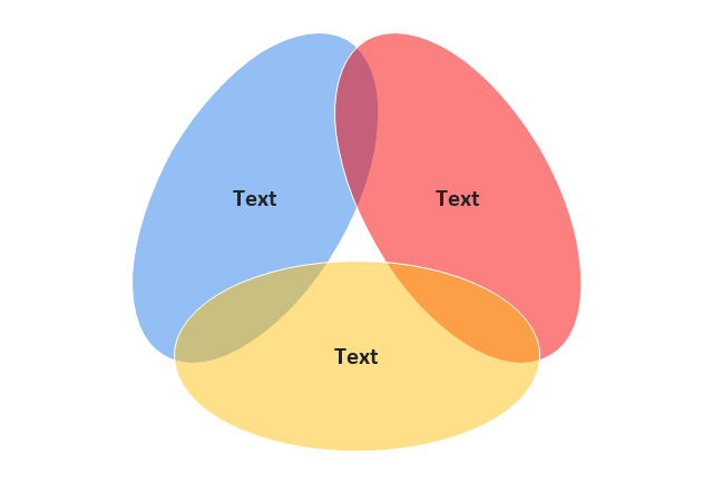
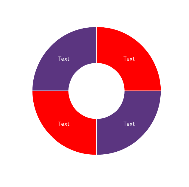
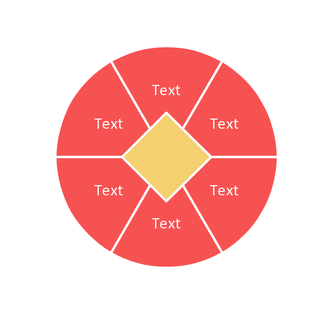
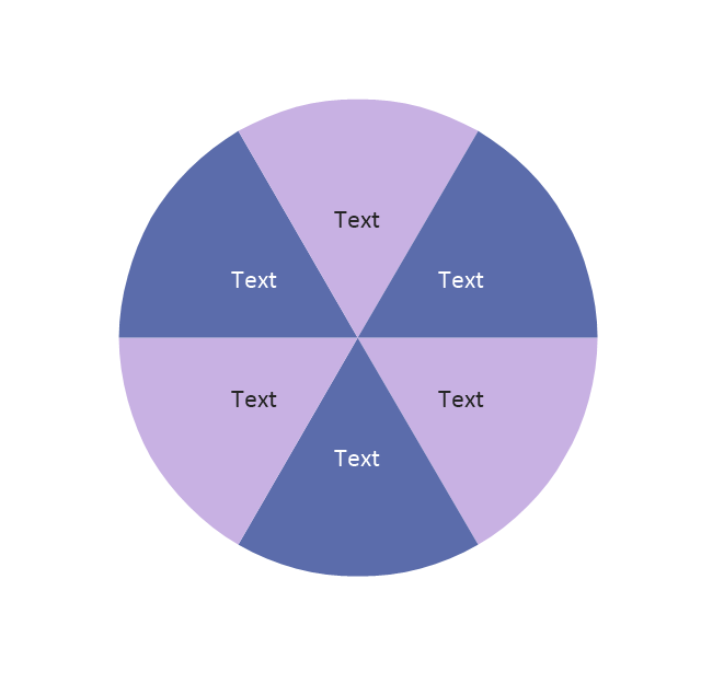
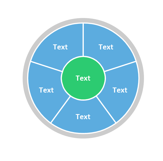
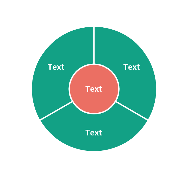
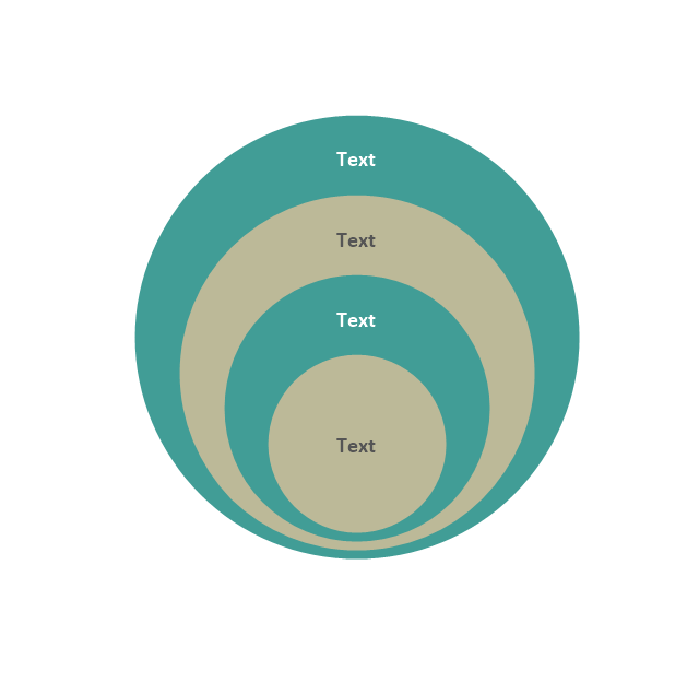
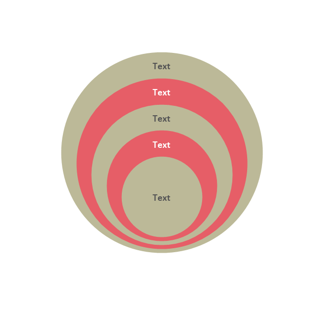
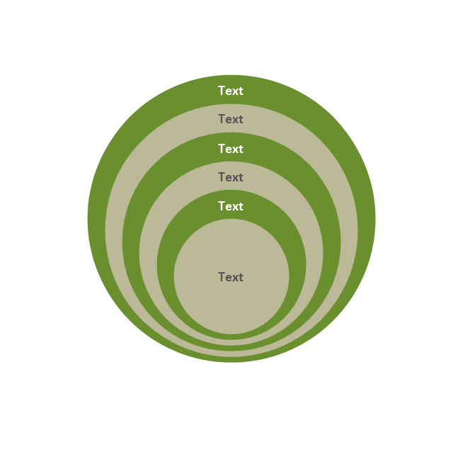
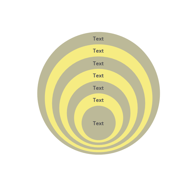
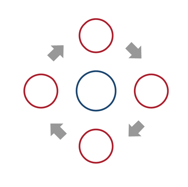
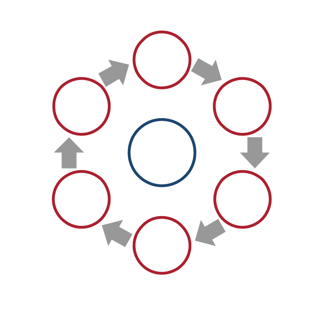
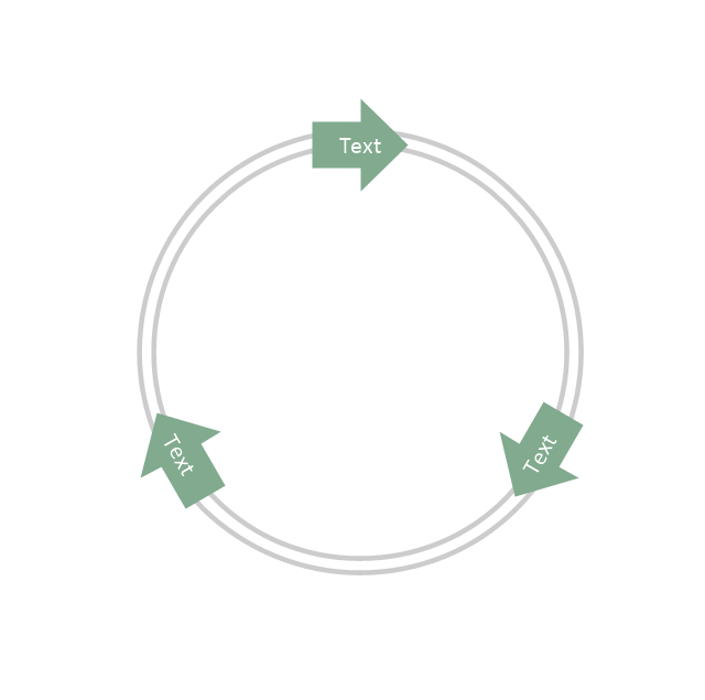
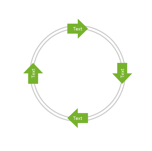
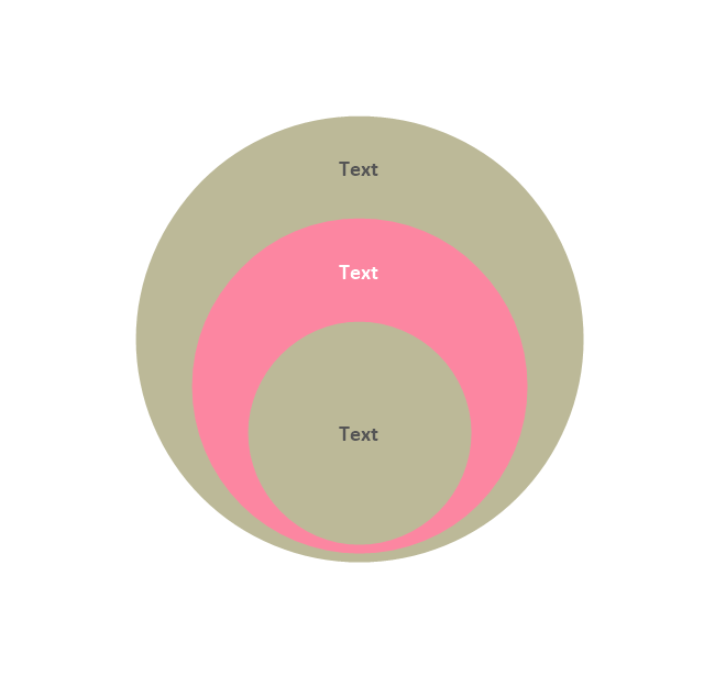
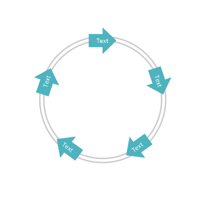
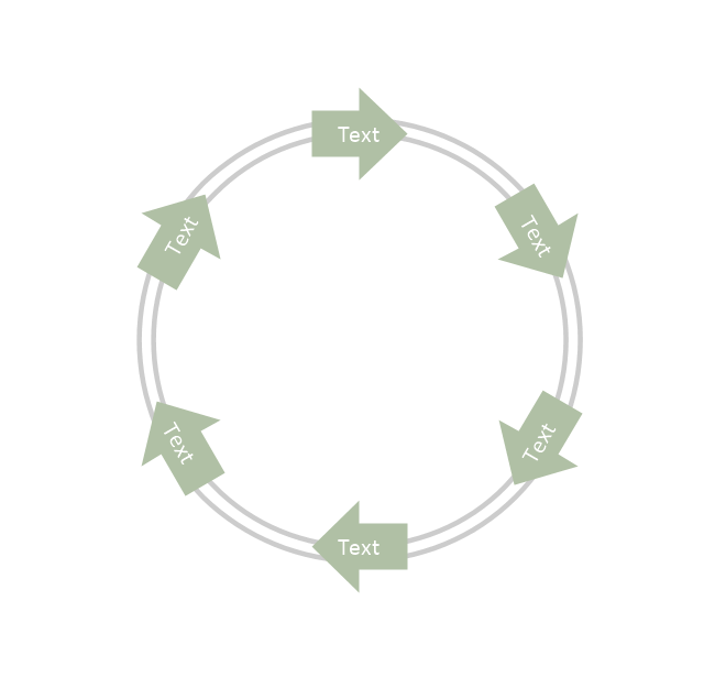
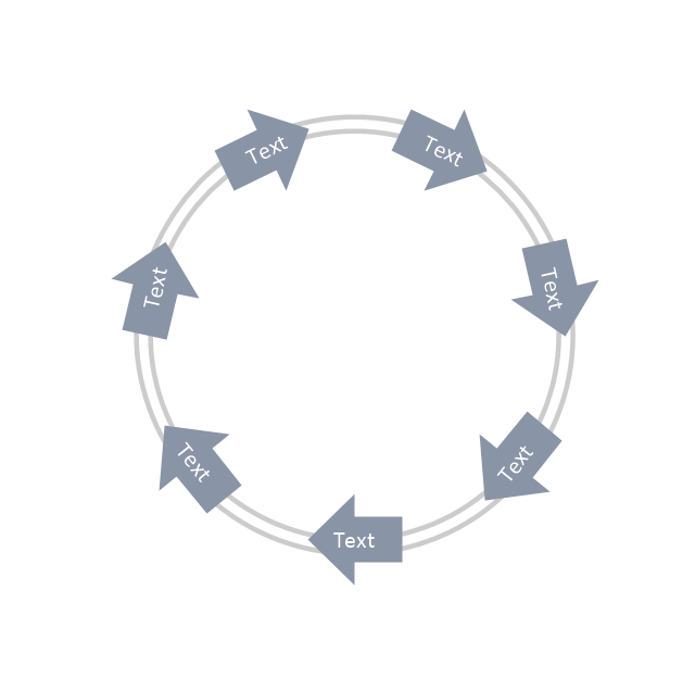
The vector stencils library "Circular diagrams" contains 42 templates of circular diagrams: circular arrow diagram, circular motion diagram, arrow ring chart, doughnut chart (donut chart), circle pie chart, diamond pie chart, circle diagram, pie chart, ring chart, loop diagram, block loop diagram, arrow loop circle, crystal diagram, triangular diagram, diamond diagram, pentagon diagram, hexagon diagram, heptagon diagram, cycle diagram (cycle chart), stacked Venn diagram (onion diagram), arrow circle diagram.
Use these shapes to illustrate your marketing and sales documents, presentations, webpages and infographics in the ConceptDraw PRO diagramming and vector drawing software extended with the Target and Circular Diagrams solution from the Marketing area of ConceptDraw Solution Park.
www.conceptdraw.com/ solution-park/ marketing-target-and-circular-diagrams
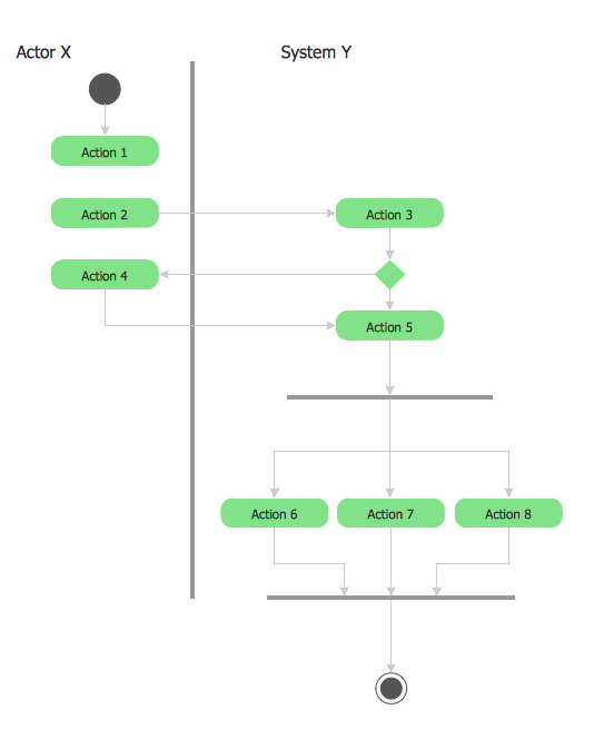
UML 2 4 Process Flow Diagram
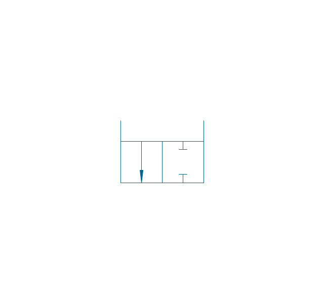
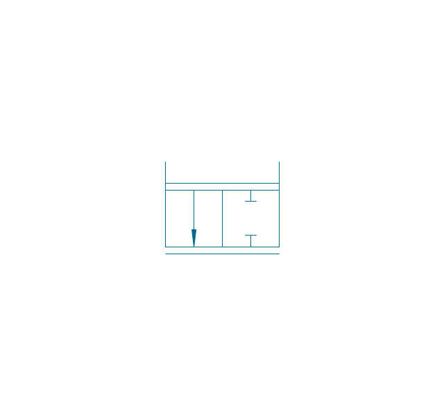
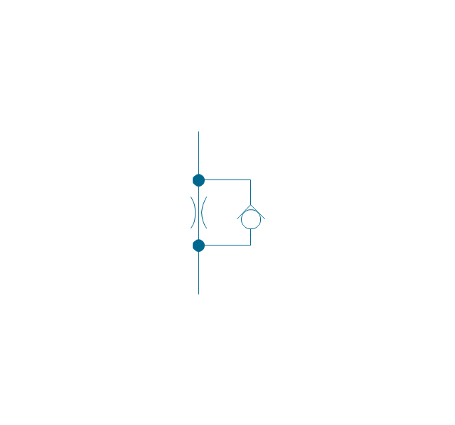
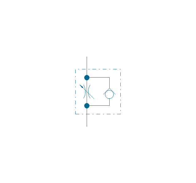
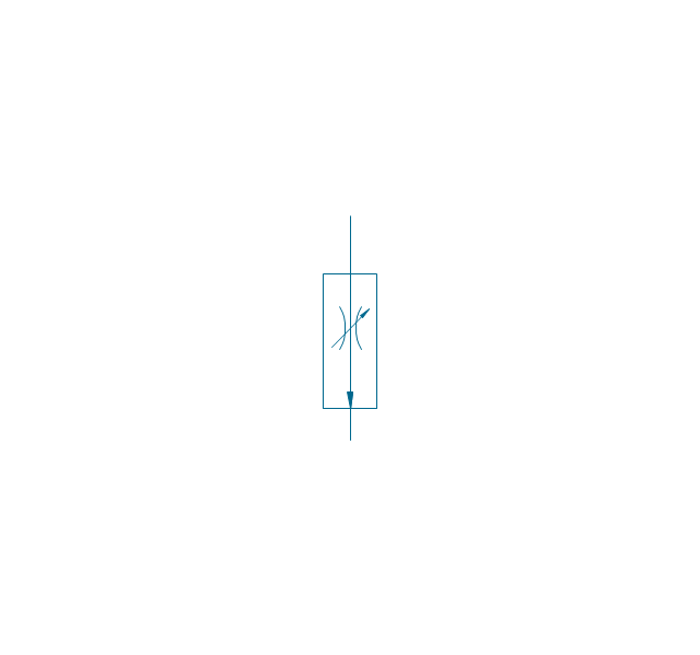
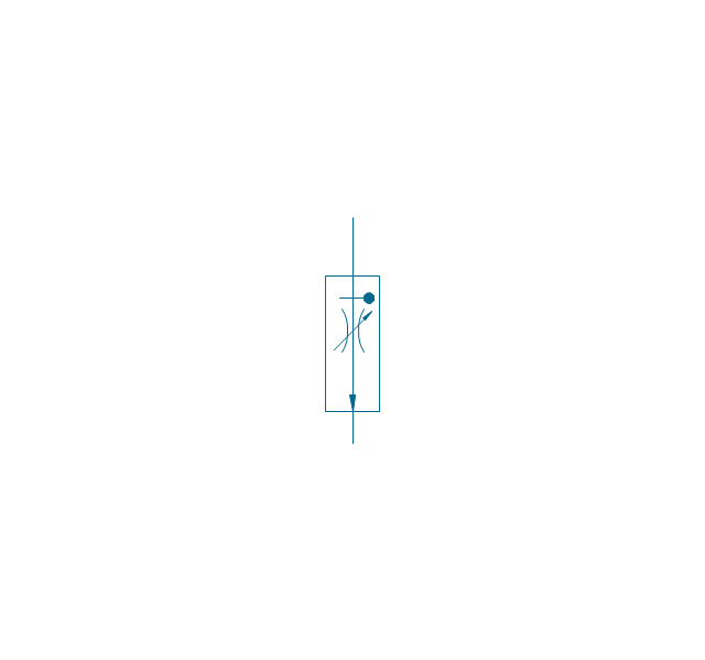
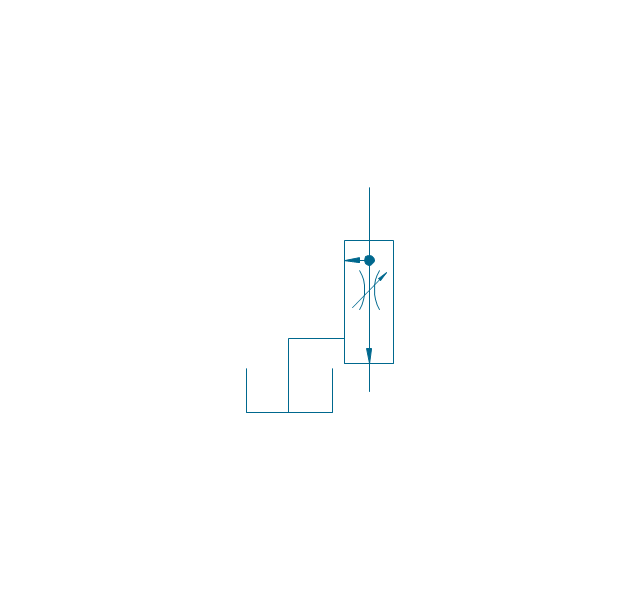
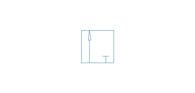
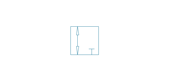
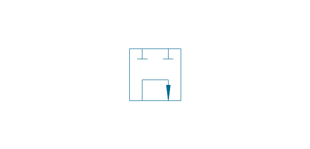
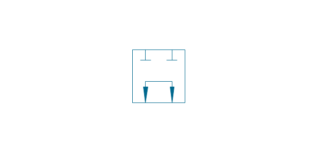
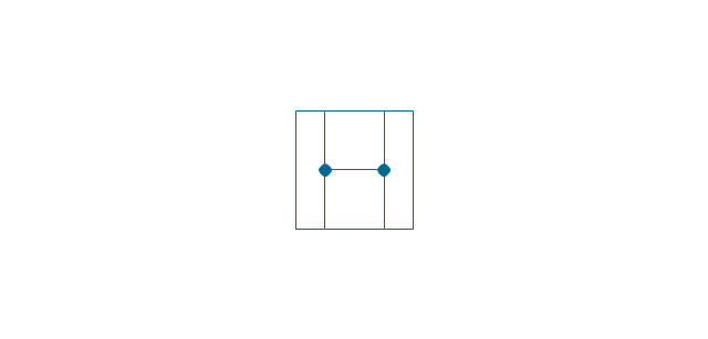
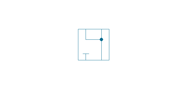
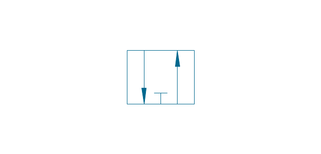
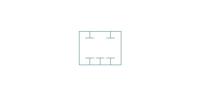
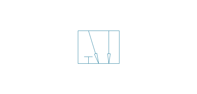
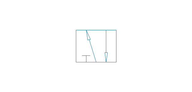
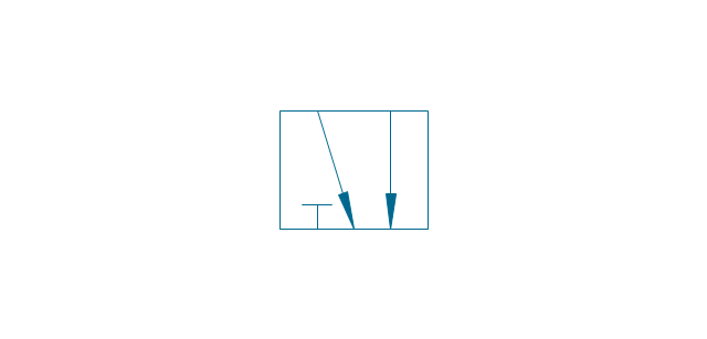
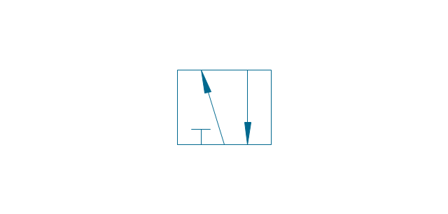
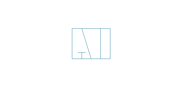
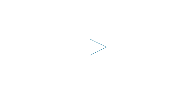
This sample was created in ConceptDraw PRO diagramming and vector drawing software using the UML Activity Diagram library of the Rapid UML Solution from the Software Development area of ConceptDraw Solution Park.The vector stencils library "Valve assembly" contains 141 symbols of pressure and flow regulators, flow direction indicators, controls, and symbols to design flow paths of control valves in fluid power systems.
Use these valve assembly shapes to design the engineering drawings of hydraulic and pneumatic valve assemblies
in the ConceptDraw PRO diagramming and vector drawing software extended with the Mechanical Engineering solution from the Engineering area of ConceptDraw Solution Park.
www.conceptdraw.com/ solution-park/ engineering-mechanical
The vector stencils library "Status indicators" contains 41 visual status indicators. Each status indicator can visualize one of 2-6 information states and have a caption.
Use it to create your business performance dashboards in the ConceptDraw PRO diagramming and vector drawing software extended with the Status Dashboard solution from the area "What is a Dashboard" of ConceptDraw Solution Park.
Use it to create your business performance dashboards in the ConceptDraw PRO diagramming and vector drawing software extended with the Status Dashboard solution from the area "What is a Dashboard" of ConceptDraw Solution Park.
HelpDesk
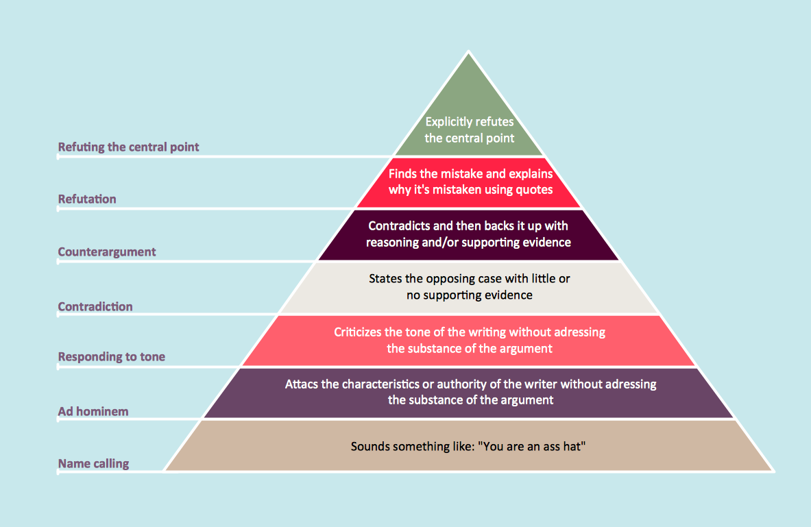
How to Draw a Pyramid Diagram in ConceptDraw PRO
Pyramid diagram (triangle diagram) is used to represent data, which have hierarchy and basics. Due to the triangular form of diagram, each pyramid section has a different width. The width of the segment shows the level of its hierarchy. Typically, the top of the pyramid is the data that are more important than the base data. Pyramid scheme can be used to show proportional and hierarchical relationships between some logically related items, such as departments within an organization, or successive elements of any process. This type of diagram is often used in marketing to display hierarchical related data, but it can be used in a variety of situations. ConceptDraw PRO allows you to make a pyramid diagram, quickly and easily using special libraries.- Soccer Positions 4 4 2
- Soccer Ball 4 4 2
- Football Positions 4 4 2
- Soccer (Football) Formation | Association football (soccer) formation ...
- Association football (soccer) formation 3- 4 -3 | Association football ...
- Soccer (Football) Formation | I Formation (Offense) Diagram ...
- Association football (soccer) formation 4 -3-3 | Soccer (Football ...
- Goal Line Formation (Offense/Defense) Diagram | Goal line ...
- Defensive Formation – 4 -3 Defense Diagram | Defensive formation ...
- Association football (soccer) formation 4 -3-3 | Soccer (Football ...
- Association football (soccer) formation 3- 2 -5 (WM) | Soccer (Football ...
- Soccer (Football) Formation | Shotgun Formation (Offense) Diagram ...
- Football | Soccer (Football) Formation | Soccer (Football) Diagram ...
- Association football (soccer) field dimensions | Association football ...
- Association football (soccer) formation 2 –3–5 (pyramid) | Soccer ...
- Offensive Play – Double Wing Wedge – Vector Graphic Diagram ...
- Soccer (Football) Formation | Soccer (Football) Positions ...
- Association football (soccer) positions | Design elements - Football ...
- Soccer (Football) Formation | Defensive Formation – 4 -3 Defense ...
- Defensive play - Under front | Soccer (Football) Formation ...
-formation-diagram-association-football-(soccer)-formation-4-4-2.png--diagram-flowchart-example.png)
-formation-diagram-association-football-(soccer)-formation-4-4-1-1.png--diagram-flowchart-example.png)
-formation-diagram-association-football-(soccer)-formation-4-3-3.png--diagram-flowchart-example.png)

-formation-diagram-association-football-(soccer)-formation-3-2-5-(wm).png--diagram-flowchart-example.png)








,-1-valve-fluid-power-valves---vector-stencils-library.png--diagram-flowchart-example.png)
,-both-valves-fluid-power-valves---vector-stencils-library.png--diagram-flowchart-example.png)
,-no-valves-fluid-power-valves---vector-stencils-library.png--diagram-flowchart-example.png)
,-1-valve,-encl.-fluid-power-valves---vector-stencils-library.png--diagram-flowchart-example.png)
,-both-valves,-encl.-fluid-power-valves---vector-stencils-library.png--diagram-flowchart-example.png)
,-no-valves,-encl.-fluid-power-valves---vector-stencils-library.png--diagram-flowchart-example.png)
,-1-valve-fluid-power-valves---vector-stencils-library.png--diagram-flowchart-example.png)
,-both-valves-fluid-power-valves---vector-stencils-library.png--diagram-flowchart-example.png)
,-no-valves-fluid-power-valves---vector-stencils-library.png--diagram-flowchart-example.png)
,-1-valve,-encl.-fluid-power-valves---vector-stencils-library.png--diagram-flowchart-example.png)
,-both-valves,-encl.-fluid-power-valves---vector-stencils-library.png--diagram-flowchart-example.png)
,-no-valves,-encl.-fluid-power-valves---vector-stencils-library.png--diagram-flowchart-example.png)


-fluid-power-valves---vector-stencils-library.png--diagram-flowchart-example.png)































































-valve-assembly---vector-stencils-library.png--diagram-flowchart-example.png)
-valve-assembly---vector-stencils-library.png--diagram-flowchart-example.png)
-valve-assembly---vector-stencils-library.png--diagram-flowchart-example.png)
-valve-assembly---vector-stencils-library.png--diagram-flowchart-example.png)
-valve-assembly---vector-stencils-library.png--diagram-flowchart-example.png)
-valve-assembly---vector-stencils-library.png--diagram-flowchart-example.png)
-valve-assembly---vector-stencils-library.png--diagram-flowchart-example.png)
-valve-assembly---vector-stencils-library.png--diagram-flowchart-example.png)
-valve-assembly---vector-stencils-library.png--diagram-flowchart-example.png)
-valve-assembly---vector-stencils-library.png--diagram-flowchart-example.png)
-valve-assembly---vector-stencils-library.png--diagram-flowchart-example.png)
-valve-assembly---vector-stencils-library.png--diagram-flowchart-example.png)
-valve-assembly---vector-stencils-library.png--diagram-flowchart-example.png)
-valve-assembly---vector-stencils-library.png--diagram-flowchart-example.png)
-valve-assembly---vector-stencils-library.png--diagram-flowchart-example.png)
-valve-assembly---vector-stencils-library.png--diagram-flowchart-example.png)
-valve-assembly---vector-stencils-library.png--diagram-flowchart-example.png)
-valve-assembly---vector-stencils-library.png--diagram-flowchart-example.png)
-valve-assembly---vector-stencils-library.png--diagram-flowchart-example.png)
-valve-assembly---vector-stencils-library.png--diagram-flowchart-example.png)
-valve-assembly---vector-stencils-library.png--diagram-flowchart-example.png)
-valve-assembly---vector-stencils-library.png--diagram-flowchart-example.png)
-valve-assembly---vector-stencils-library.png--diagram-flowchart-example.png)
-valve-assembly---vector-stencils-library.png--diagram-flowchart-example.png)













-valve-assembly---vector-stencils-library.png--diagram-flowchart-example.png)

-valve-assembly---vector-stencils-library.png--diagram-flowchart-example.png)







-valve-assembly---vector-stencils-library.png--diagram-flowchart-example.png)
-valve-assembly---vector-stencils-library.png--diagram-flowchart-example.png)


-valve-assembly---vector-stencils-library.png--diagram-flowchart-example.png)


