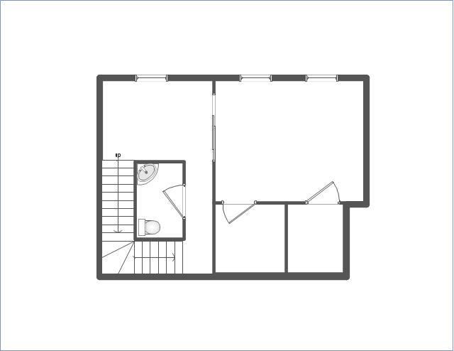
Use this template to develop the home layouts, space plans, interior design, kitchen and bathroom design, architectural and construction documents using ConceptDraw PRO diagramming and vector drawing software.
"A floor plan is the most fundamental architectural diagram, a view from above showing the arrangement of spaces in building in the same way as a map, but showing the arrangement at a particular level of a building. Technically it is a horizontal section cut through a building (conventionally at three feet / one metre above floor level), showing walls, windows and door openings and other features at that level. The plan view includes anything that could be seen below that level: the floor, stairs (but only up to the plan level), fittings and sometimes furniture. Objects above the plan level (e.g. beams overhead) can be indicated as dotted lines." [Architectural drawing. Wikipedia]
The Home floor plan template is included in the Floor Plans solution from the Building Plans area of ConceptDraw Solution Park.
www.conceptdraw.com/ solution-park/ floor-plans
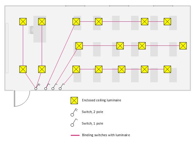
This electrical floor plan sample shows the lighting layout on the classroom reflected ceiling plan.
"Architectural lighting design is a field within architecture and architectural engineering that concerns itself primarily with the illumination of buildings. The objective of architectural lighting design is to obtain sufficient light for the purposes of the building, balancing factors of initial and operating cost, appearance, and energy efficiency. Lighting designers are often specialists who must understand the physics of light production and distribution, and the physiology and psychology of light perception by humans. Architectural lighting design is generally concerned with the permanent illumination of a structure. Concert and theatrical lighting have different purposes and practitioners." [Architectural lighting design. Wikipedia]
The electrical floor plan example "Classroom lighting - Reflected ceiling plan" was created using the ConceptDraw PRO diagramming and vector drawing software extended with the Electric and Telecom Plans solution from the Building plans area of ConceptDraw Solution Park.
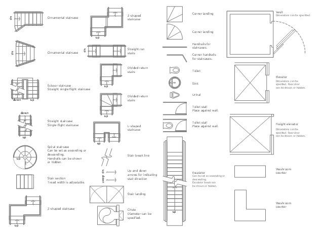
The design elements library Building core contains 80 symbols of stairs, elevators, escalators, restroom fixtures, and a safe.
Use the shapes library Building core to draw the structural diagrams, bathroom layouts, building automation, architectural drawings, and riser diagrams, as well as space plans, store and shopping mall plans, and facility planning, plant layouts using the ConceptDraw PRO diagramming and vector drawing software.
"In architecture and building engineering, a floor plan otherwise known as a Scottish plan is a drawing to scale, showing a view from above, of the relationships between rooms, spaces and other physical features at one level of a structure.
The term may be used in general to describe any drawing showing the physical layout of objects.
A floor plan could show:
Interior walls and hallways;
Restrooms;
Windows and doors;
Appliances such as stoves, refrigerators, water heater etc.;
Interior features such as fireplaces, saunas and whirlpools;
The use of all rooms shall be indicated." [Floor plan. Wikipedia]
The vector stencils library Building core is provided by the Floor Plans solution from the Building Plans area of ConceptDraw Solution Park.
This cafe electrical floor plan sample shows the outlet and switch layout.
"An electrical drawing, is a type of technical drawing that shows information about power, lighting, and communication for an engineering or architectural project. Any electrical working drawing consists of "lines, symbols, dimensions, and notations to accurately convey an engineering's design to the workers, who install the electrical system on the job".
A complete set of working drawings for the average electrical system in large projects usually consists of:
(1) A plot plan showing the building's location and outside electrical wiring.
(2) Floor plans showing the location of electrical systems on every floor.
(3) Power-riser diagrams showing panel boards.
(4) Control wiring diagrams.
(5) Schedules and other information in combination with construction drawings.
Electrical drafters prepare wiring and layout diagrams used by workers who erect, install, and repair electrical equipment and wiring in communication centers, power plants, electrical distribution systems, and buildings." [Electrical drawing. Wikipedia]
The outlet and switch layout example "Cafe electrical floor plan" was created using the ConceptDraw PRO diagramming and vector drawing software extended with the Electric and Telecom Plans solution from the Building Plans area of ConceptDraw Solution Park.
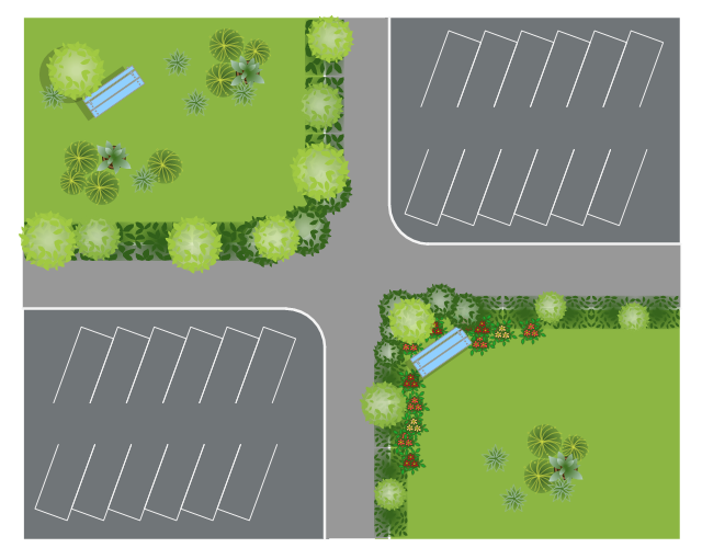
This site plan is the sample of landscape architecture drawing.
"A site plan is an architectural plan, landscape architecture document, and a detailed engineering drawing of proposed improvements to a given lot. A site plan usually shows a building footprint, travelways, parking, drainage facilities, sanitary sewer lines, water lines, trails, lighting, and landscaping and garden elements. ...
Site planning in landscape architecture and architecture refers to the organizational stage of the landscape design process. It involves the organization of land use zoning, access, circulation, privacy, security, shelter, land drainage, and other factors. This is done by arranging the compositional elements of landform, planting, water, buildings and paving and building. Site planning generally begins by assessing a potential site for development through site analysis. Information about slope, soils, hydrology, vegetation, parcel ownership, orientation, etc. are assessed and mapped. By determining areas that are poor for development (such as floodplain or steep slopes) and better for development, the planner or architect can assess optimal location and design a structure that works within this space." [Site plan. Wikipedia]
The landscape design example "Site plan" was created using the ConceptDraw PRO diagramming and vector drawing software extended with the Site Plans solution from the Building Plans area of ConceptDraw Solution Park.
 AWS Architecture Diagrams
AWS Architecture Diagrams with powerful drawing tools and numerous predesigned Amazon icons and AWS simple icons is the best for creation the AWS Architecture Diagrams, describing the use of Amazon Web Services or Amazon Cloud Services, their application for development and implementation the systems running on the AWS infrastructure. The multifarious samples give you the good understanding of AWS platform, its structure, services, resources and features, wide opportunities, advantages and benefits from their use; solution’s templates are essential and helpful when designing, description and implementing the AWS infrastructure based systems. Use them in technical documentation, advertising and marketing materials, in specifications, presentation slides, whitepapers, datasheets, posters, etc.
- Building Drawing Design Element: Plumbing | Interior Design ...
- Café Floor Plan Design Software | How To Create Restaurant Floor ...
- How To use Building Plan Examples | Making Architectural Designs ...
- How To Use Floor Plan Software | Restaurant Floor Plans Samples ...
- Electrical Drawing Software | How To use House Electrical Plan ...
- Making Architectural Designs | How To use House Plan Software ...
- Café Floor Plan Design Software | Cafe Floor Plans | How To Create ...
- CAD Drawing Software for Architectural Designs ... - Conceptdraw.com
- Restaurant Floor Plans Samples
- Network Architecture | How To Create Restaurant Floor Plans in ...
- CAD Drawing Software for Architectural Designs | How To use ...
- Landscape architecture with ConceptDraw PRO | CAD Drawing ...
- How To use Architect Software | CAD Drawing Software for ...
- Network Architecture | How To use Architect Software | Diagramming ...
- How To Create Restaurant Floor Plans in Minutes | Bubble diagrams ...
- Landscape architecture with ConceptDraw PRO | Create Floor Plans ...
- How To Create Home Plan with Examples | Restaurant Floor Plans ...
- CAD Software for Architectural Designs
- How To use House Design Software | CAD Drawing Software for ...
- How To use Building Plan Examples | How To use House Plan ...


