Building Drawing. Design Element — Plumbing

How To use House Electrical Plan Software


Mechanical Drawing Symbols

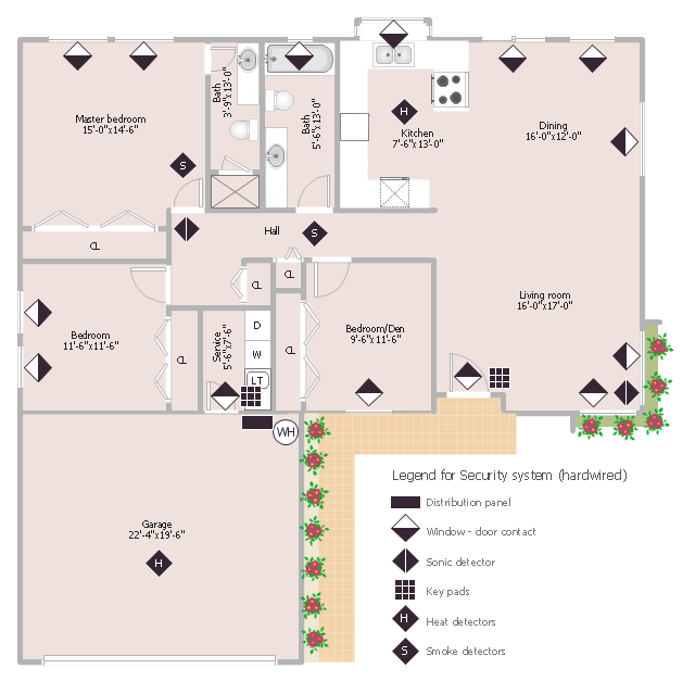
This sample was created on the base of the floor plan with security system device symbols from the website of the California State University, Sacramento. [imet.csus.edu/ imet1/ denyer/ mhs_ denyer/ drafting/ arch_ ch_ 31/ 31-28.jpg]
Legend for the security system hardware includes distribution panel, window-door contact, sonic detector, key pads, heat detectors, smoke detectors.
The example "Security system floor plan" was created using the ConceptDraw PRO diagramming and vector drawing software extended with the Security and Access Plans solution from the Building Plans area of ConceptDraw Solution Park.
Security system floor plan
Piping and Instrumentation Diagram Software

The vector stencils library "Valves" contains 91 symbols of piping and plumbing valves.
"A valve is a device that regulates, directs or controls the flow of a fluid (gases, liquids, fluidized solids, or slurries) by opening, closing, or partially obstructing various passageways. Valves are technically valves fittings, but are usually discussed as a separate category. In an open valve, fluid flows in a direction from higher pressure to lower pressure.
The simplest, and very ancient, valve is simply a freely hinged flap which drops to obstruct fluid (gas or liquid) flow in one direction, but is pushed open by flow in the opposite direction. This is called a check valve, as it prevents or "checks" the flow in one direction.
People in developed nations use valves in their daily lives, including plumbing valves, such as taps for tap water, gas control valves on cookers, small valves fitted to washing machines and dishwashers, safety devices fitted to hot water systems..." [Valve. Wikipedia]
Use the design elements library "Valves" to draw building plans, schematic diagrams, blueprints, or technical drawings of industrial piping systems; process, vacuum, and fluids piping; hydraulics piping; air and gas piping; materials distribution; and liquid transfer systems using the ConceptDraw PRO diagramming and vector drawing software.
The shapes library "Valves" is included in the Plumbing and Piping Plans solution from the Building Plans area of ConceptDraw Solution Park.
Valve symbols

Half Pipe Plans

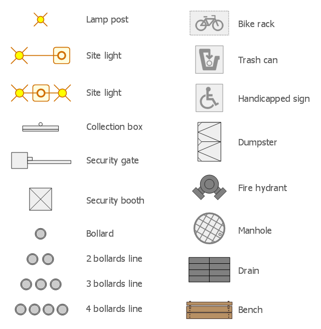
The design elements library Site accessories contains 18 symbols of vehicle access control equipment (tollbooth, tollgate, parking fees payment box), a handicapped sign, outdoor lighting, and garbage receptacles.
"A site plan is an architectural plan, landscape architecture document, and a detailed engineering drawing of proposed improvements to a given lot. A site plan usually shows a building footprint, travelways, parking, drainage facilities, sanitary sewer lines, water lines, trails, lighting, and landscaping and garden elements." [Site plan. Wikipedia]
Use the Site accessories library to design plans, equipment layouts and maps of sites, parking lots, residential and commercial landscapes, parks, yards, plats, outdoor recreational facilities, and irrigation systems using ConceptDraw PRO diagramming and vector drawing software.
The design elements library Site accessories is contained in the Site Plans solution from the Building Plans area of ConceptDraw Solution Park.
Technical Drawing Software

Electrical and Telecom Plan Software

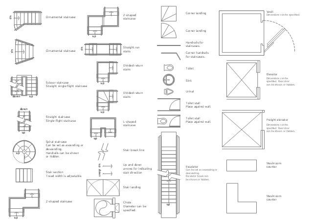
The design elements library Building core contains 80 symbols of stairs, elevators, escalators, restroom fixtures, and a safe.
Use the shapes library Building core to draw the structural diagrams, bathroom layouts, building automation, architectural drawings, and riser diagrams, as well as space plans, store and shopping mall plans, and facility planning, plant layouts using the ConceptDraw PRO diagramming and vector drawing software.
"In architecture and building engineering, a floor plan otherwise known as a Scottish plan is a drawing to scale, showing a view from above, of the relationships between rooms, spaces and other physical features at one level of a structure.
The term may be used in general to describe any drawing showing the physical layout of objects.
A floor plan could show:
Interior walls and hallways;
Restrooms;
Windows and doors;
Appliances such as stoves, refrigerators, water heater etc.;
Interior features such as fireplaces, saunas and whirlpools;
The use of all rooms shall be indicated." [Floor plan. Wikipedia]
The vector stencils library Building core is provided by the Floor Plans solution from the Building Plans area of ConceptDraw Solution Park.
Cisco Network Design. Cisco icons, shapes, stencils, symbols and design elements

Physical Security Plan

Electrical Symbols — Power Sources

Electrical Symbols — Thermo

Gym Floor Plan

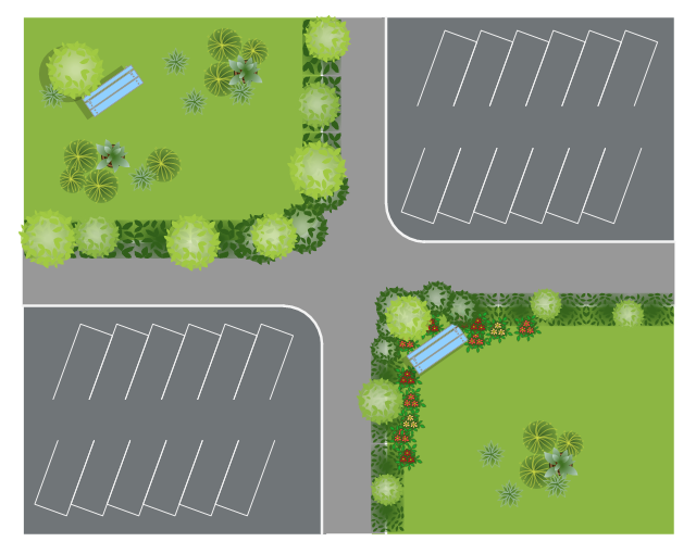
This site plan is the sample of landscape architecture drawing.
"A site plan is an architectural plan, landscape architecture document, and a detailed engineering drawing of proposed improvements to a given lot. A site plan usually shows a building footprint, travelways, parking, drainage facilities, sanitary sewer lines, water lines, trails, lighting, and landscaping and garden elements. ...
Site planning in landscape architecture and architecture refers to the organizational stage of the landscape design process. It involves the organization of land use zoning, access, circulation, privacy, security, shelter, land drainage, and other factors. This is done by arranging the compositional elements of landform, planting, water, buildings and paving and building. Site planning generally begins by assessing a potential site for development through site analysis. Information about slope, soils, hydrology, vegetation, parcel ownership, orientation, etc. are assessed and mapped. By determining areas that are poor for development (such as floodplain or steep slopes) and better for development, the planner or architect can assess optimal location and design a structure that works within this space." [Site plan. Wikipedia]
The landscape design example "Site plan" was created using the ConceptDraw PRO diagramming and vector drawing software extended with the Site Plans solution from the Building Plans area of ConceptDraw Solution Park.
Landscape design
 Plumbing and Piping Plans
Plumbing and Piping Plans solution extends ConceptDraw DIAGRAM.2.2 software with samples, templates and libraries of pipes, plumbing, and valves design elements for developing of water and plumbing systems, and for drawing Plumbing plan, Piping plan, PVC Pipe plan, PVC Pipe furniture plan, Plumbing layout plan, Plumbing floor plan, Half pipe plans, Pipe bender plans.
How To use House Design Software

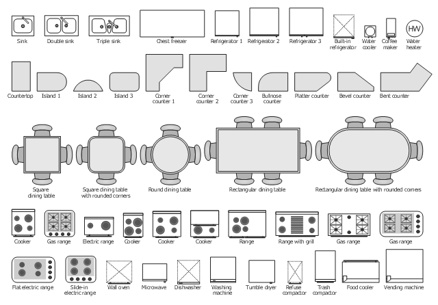
The vector stencils library "Kitchen, dining room" contains 48 kitchen and dining room furniture and equipment icons.
Use it for drawing the basic floor plans, kitchen and dining room interior design with ConceptDraw PRO diagramming and vector drawing software.
The floorplan shapes example "Design elements - Kitchen, dining room" is included in the Basic Floor Plans solution from the Building Plans area of ConceptDraw Solution Park.
Floorplan shapes
- Symbol Water Air Release Valve
- Mechanical Drawing Symbols | How To use House Electrical Plan ...
- Symbol Of A Water Tank On An Architectural Plan
- Water Installation Symbols
- Valves
- Symbol Of Water Tap In Mechanical Designs
- Mechanical Drawing Symbols | Electrical Symbols , Electrical ...
- Plumbing and Piping Plans | Mechanical Drawing Symbols | Pipe ...
- Unit Water Symbol
- Radiator Symbol Technical Drawing
- Water Tank Floor Plan
- Process Flow Diagram Symbols | Mechanical Drawing Symbols ...
- Plumbing and Piping Plans | Architectural Symbol Of Water Heater
- Mechanical Drawing Symbols | Process Flow Diagram Symbols ...
- Water Engineering Drawing Symbols
- Symbol Of A Water Fountain Drawings Site Plan
- Water Tap Drawing Symbol
- Pipeline Anchor Support Drafting Symbol
- Water Sensor Symbol
- Design elements - Bathroom | Interior Design. Plumbing — Design ...