This vector stencils library contains 23 events symbols for drawing business process diagrams (BPMN 1.2).
An Event is something that happens during the course of a business process. These events affect the flow of the process and usually have a cause or an impact. There are three types of Events, based on when they affect the flow: Start, Intermediate and End.
An Event is something that happens during the course of a business process. These events affect the flow of the process and usually have a cause or an impact. There are three types of Events, based on when they affect the flow: Start, Intermediate and End.
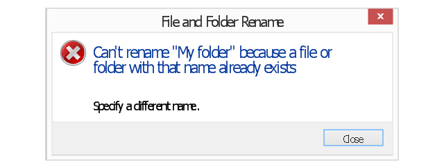
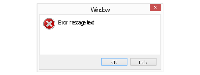
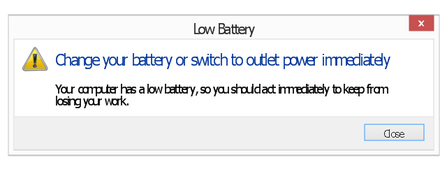
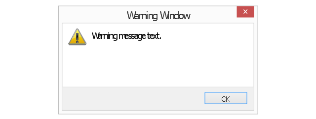
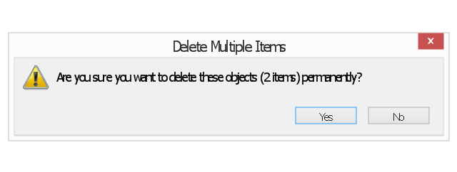
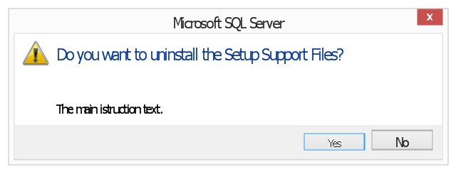
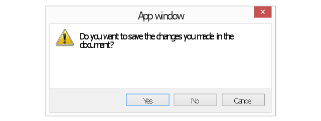
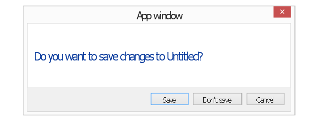
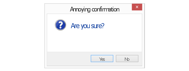
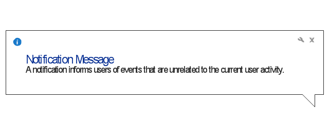
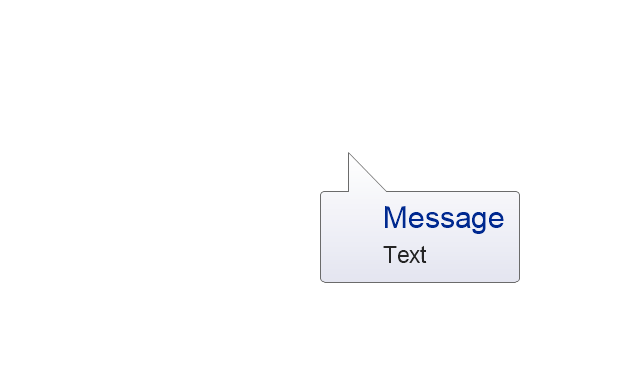
The vector stencils library "Messages" contains 10 Message dialog elements.
Use this notification dialog UI icon set to design graphic user interface (GUI) of your Windows 8 software application.
"A message dialog is an overlay UI element that provides a stable and contextual surface that is always modal and explicitly dismissed. Message dialogs appear at a consistent location on the screen. ...
Error messages that apply to the overall app context use message dialogs. ...
- Use message dialogs to convey urgent information that the user must see and acknowledge before continuing. ...
- Use message dialogs to present blocking questions that require the user's input. A blocking question is a question where the application cannot make a choice on the user's behalf, and cannot continue to fulfill it's value proposition to the user. A blocking question should present clear choices to the user. It is not a question that can be ignored or postponed.
- Use message dialogs to ask for explicit action from the user or to deliver a message that is important for the user to acknowledge. ...
- Use custom dialogs when the app or the system must invest a significant amount of time in the ensuing actions such that an accidental dismiss would be detrimental to the user's confidence.
- All dialogs should clearly identify the user's objective in the first line of the dialog's text (with or without a title).
- Don't use message dialogs when the app needs to confirm the user's intention for an action that the user has taken. Instead, a flyout is the appropriate surface. ...
- Don't use message dialogs for errors that are contextual to a specific place on the page, such as validation errors (in password fields, for example), use the app's canvas itself to show inline errors." [msdn.microsoft.com/ en-us/ library/ windows/ apps/ hh738363.aspx]
The notification dialogs example "Messages - Vector stencils library" was created using the ConceptDraw PRO diagramming and vector drawing software extended with the Windows 8 User Interface solution from the Software Development area of ConceptDraw Solution Park.
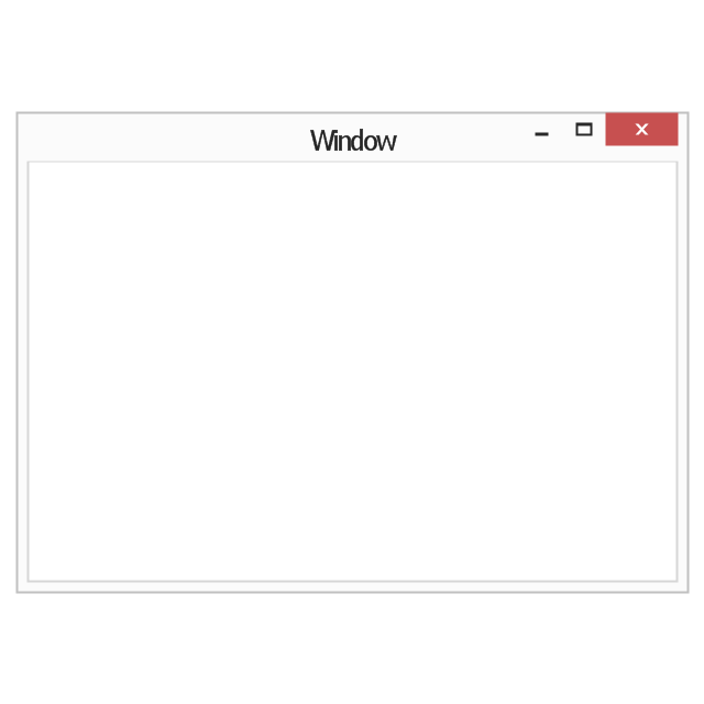
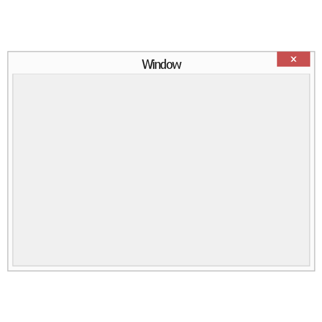
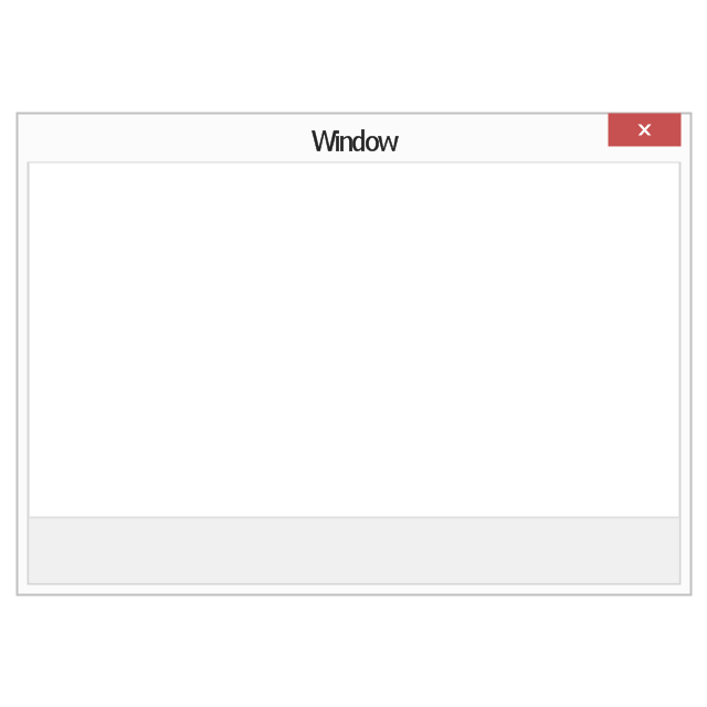
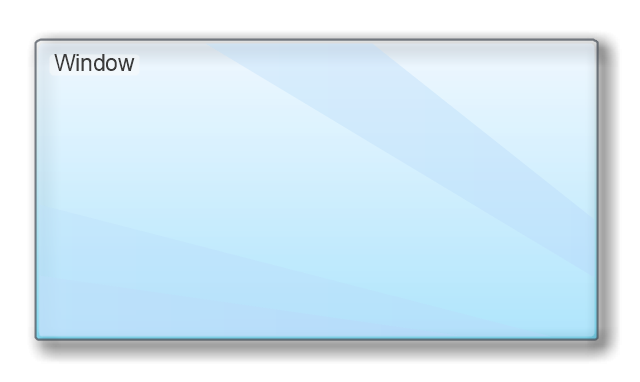
The vector stencils library "Window elements" contains 24 window elements: frames, boxes and buttons.
Use it to design graphic user interface (GUI) of your Windows 8 software application.
"A window is a graphical control element. It consists of a visual area containing some of the graphical user interface of the program it belongs to and is framed by a window decoration. It usually has a rectangular shape that can overlap with the area of other windows. It displays the output of and may allow input to one or more processes.
Windows are primarily associated with graphical displays, where they can be manipulated with a pointer by employing some kind of pointing device.
A graphical user interface (GUI) using windows as one of its main "metaphors" is called a windowing system, whose main components are the display server and the window manager." [Window (computing). Wikipedia]
The design elements example "Window elements - Vector stencils library" was created using the ConceptDraw PRO diagramming and vector drawing software extended with the Windows 8 User Interface solution from the Software Development area of ConceptDraw Solution Park.
Venn Diagram Examples for Problem Solving
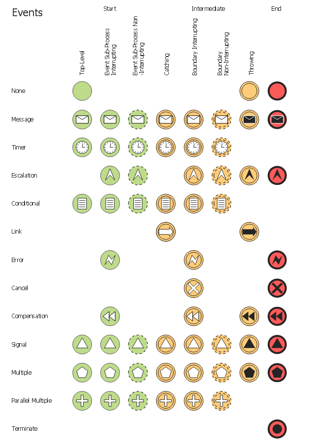
Venn diagrams are illustrations used in the branch of mathematics known as set theory. They show the mathematical or logical relationship between different groups of things (sets). A Venn diagram shows all the possible logical relations between the sets.The vector stencils library "Events" contains 17 symbols: start, intermediate and end events and none events, message, timer, error, escalation, cancel, compensation, conditional, link, signal, terminate, multiple and parralel multiple events, off-page connectors (catching and throwing).
Use these shapes for drawing business process diagrams (BPMN 2.0) using the ConceptDraw PRO diagramming and vector drawing software.
An Event is something that happens during the course of a business process. These events affect the flow of the process and usually have a cause or an impact. There are three types of Events, based on when they affect the flow: Start, Intermediate and End.
The example "Design elements - Events BPMN 2.0" is included in the Business Process Diagram solution from the Business Processes area of ConceptDraw Solution Park.
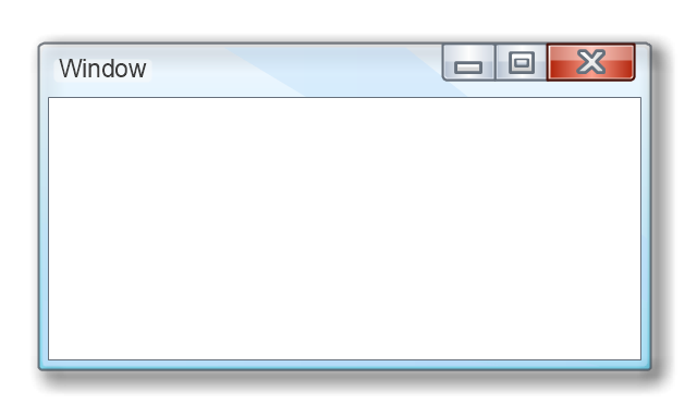
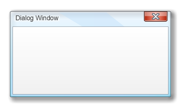
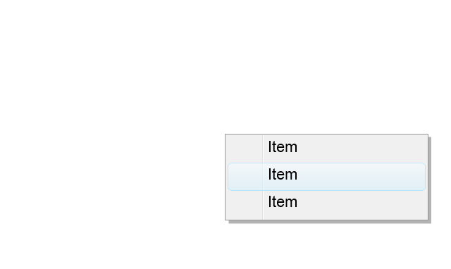
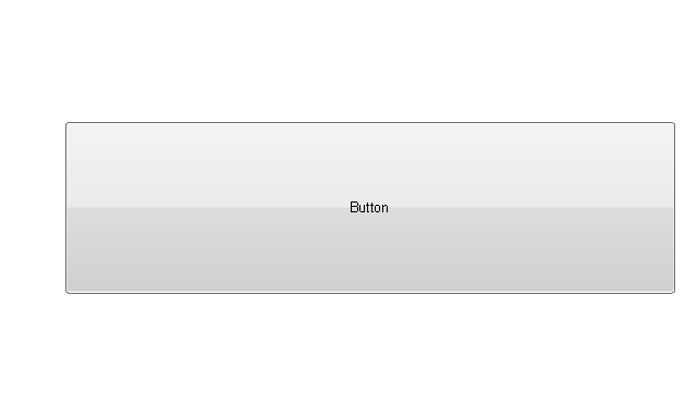
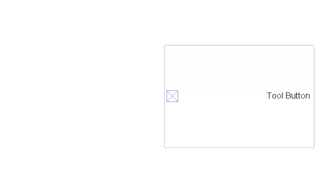
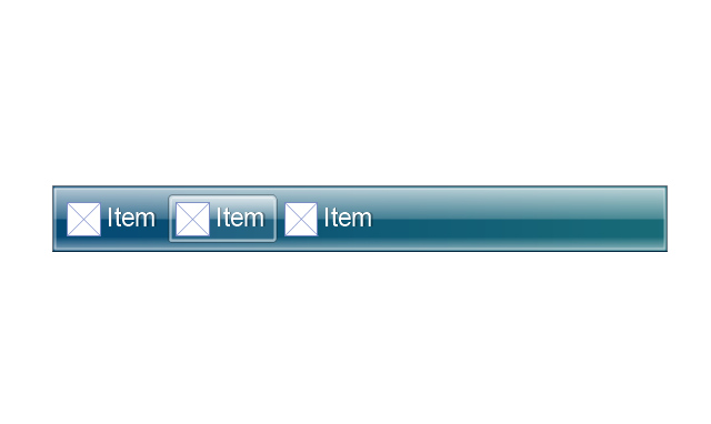
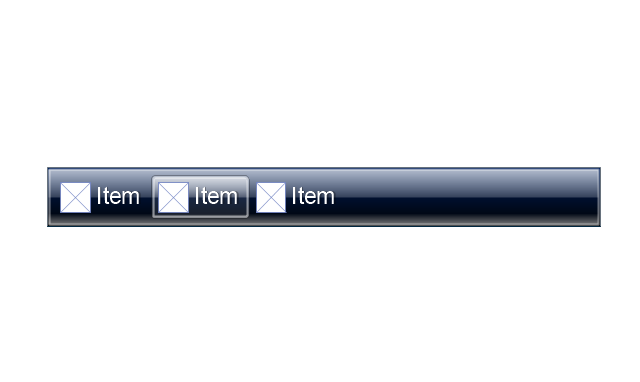
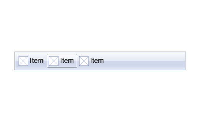
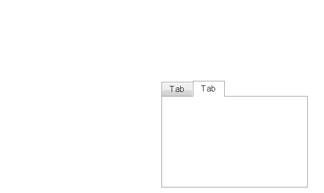
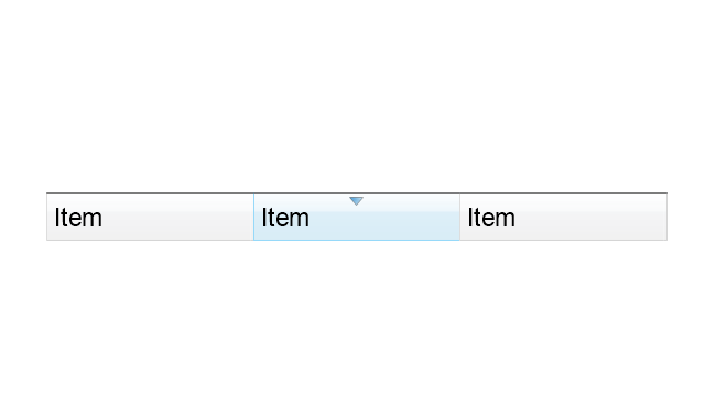
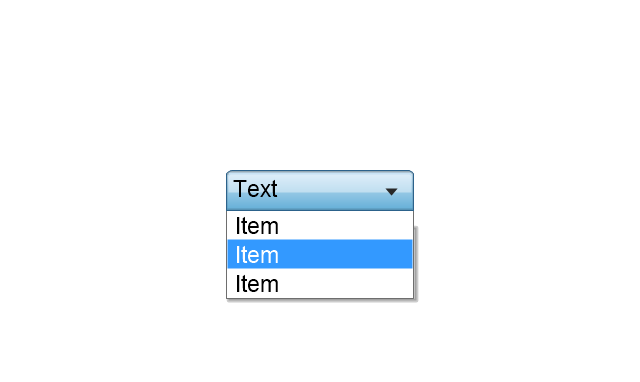
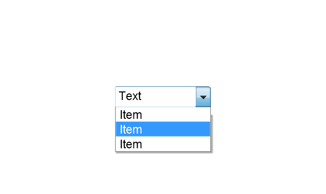
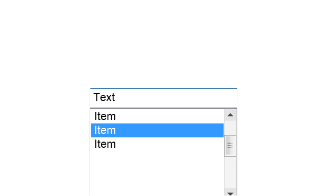
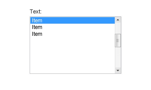
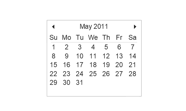
The vector stencils library "MS Windows Vista user interface" contains 76 MS Windows Vista design elements.
Use it for designing Microsoft ribbon graphic user interface (GUI) of software for computers with MS Windows Vista OS in the ConceptDraw PRO diagramming and vector drawing software extended with the Graphic User Interface solution from the Software Development area of ConceptDraw Solution Park.
Use it for designing Microsoft ribbon graphic user interface (GUI) of software for computers with MS Windows Vista OS in the ConceptDraw PRO diagramming and vector drawing software extended with the Graphic User Interface solution from the Software Development area of ConceptDraw Solution Park.
HelpDesk
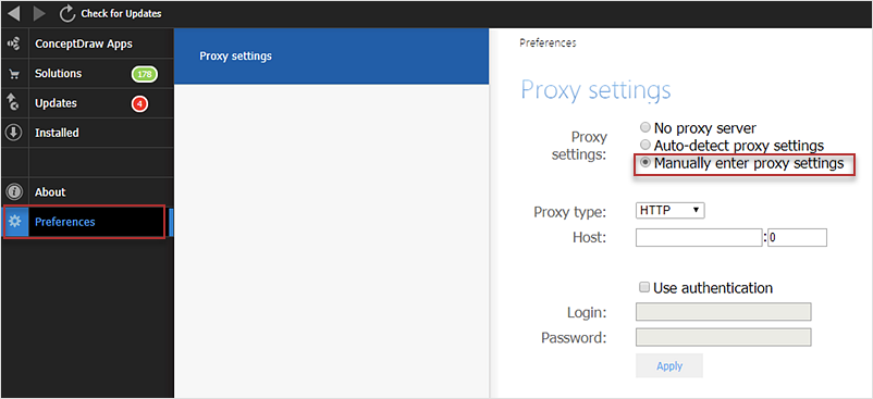
How to Download ConceptDraw Products Through a Proxy Server
If you are on a corporate network, there’s a good chance you connect to the Internet using a proxy server. Thankfully, ConceptDraw automatically detects your proxy settings and works just fine through HTTP(S) proxy servers.
 iPhone User Interface
iPhone User Interface solution extends ConceptDraw DIAGRAM software with templates, samples and libraries with large quantity of vector stencils of graphical user interface elements, Apps icons, UI patterns for designing and prototyping of the iOS applic
HelpDesk
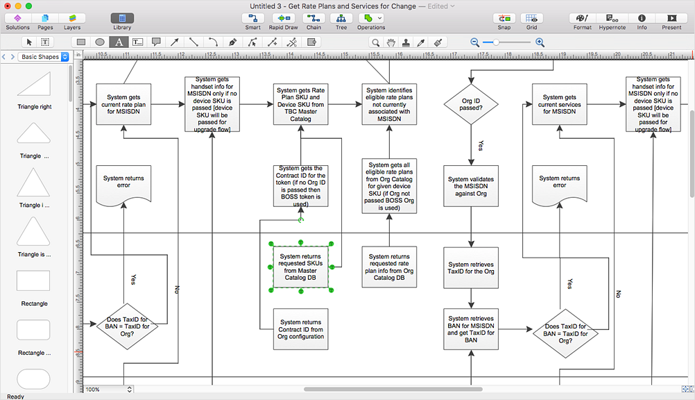
How to Open MS Visio® 2013/2016 Files on a Mac®
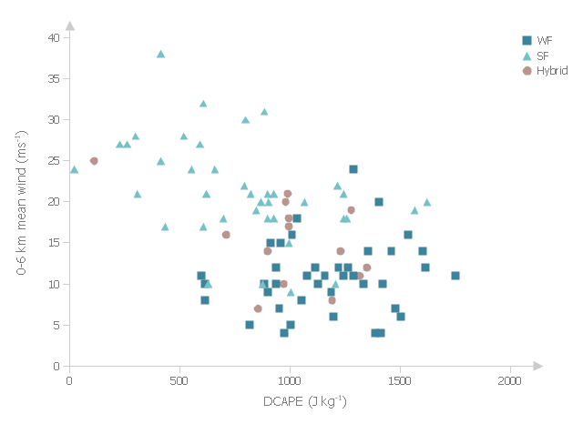
Powerful business graphics and diagramming tools is the norm and not the exception for today’s businesses. For years the de facto standard file format for business has been Microsoft Visio™. Many people involved in visual communication need software tools that will read and write using the Visio file format. With the introduction of Visio 2013, Microsoft has changed the native file format used in earlier versions of Microsoft Visio. ConceptDraw DIAGRAM v12 file import and export works round-trip with the new Visio VSDX file format.This example was drawn on the base of fig. 13 "Scatter plot of DCAPE versus 0-6 km mean wind" from the article "Examination of Derecho Environments Using Proximity Soundings" by Jeffry S. Evans on the website of Storm Prediction Center, National Oceanic and Atmospheric Administration.
"Figure 13 suggests the existence of an inverse relationship between DCAPE and mean wind when considering all derechos. Careful examination of this figure shows that this is the result of the separation into SF, WF, and hybrid categories; the SF cases are found in the upper left part of the figure, the WF cases are found in the lower right part, and the hybrid cases are in between, with some hint that they are more like the WF cases than the SF cases." [spc.noaa.gov/ publications/ evans/ bowpaper/ bowpaper.htm]
"In stratified sampling, the population is partitioned into non-overlapping groups, called strata and a sample is selected by some design within each stratum. ...
The principal reasons for using stratified random sampling rather than simple random sampling include:
1. Stratification may produce a smaller error of estimation than would be produced by a simple random sample of the same size. This result is particularly true if measurements within strata are very homogeneous.
2. The cost per observation in the survey may be reduced by stratification of the population elements into convenient groupings.
3. Estimates of population parameters may be desired for subgroups of the population. These subgroups should then be identified." [onlinecourses.science.psu.edu/ stat506/ node/ 27]
The multiserial scatterplot "Starification diagram example" was created using the ConceptDraw PRO software extended with the Seven Basic Tools of Quality solution from the Quality area of ConceptDraw Solution Park.
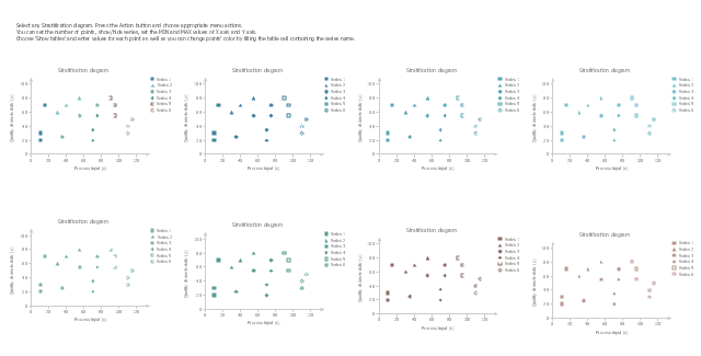
The vector stencils library "Stratification diagram" contains 8 multiseries scatterplot templates.
Use it to design your stratification diagrams with ConceptDraw PRO diagramming and vector drawing software.
"In statistics, stratified sampling is a method of sampling from a population.
In statistical surveys, when subpopulations within an overall population vary, it is advantageous to sample each subpopulation (stratum) independently. Stratification is the process of dividing members of the population into homogeneous subgroups before sampling. The strata should be mutually exclusive: every element in the population must be assigned to only one stratum. The strata should also be collectively exhaustive: no population element can be excluded. Then simple random sampling or systematic sampling is applied within each stratum. This often improves the representativeness of the sample by reducing sampling error. It can produce a weighted mean that has less variability than the arithmetic mean of a simple random sample of the population." [Stratified sampling. Wikipedia]
The stratification is one of the Seven Basic Tools of Quality. [Seven Basic Tools of Quality. Wikipedia]
The example of multiseries scatterplot templates "Design elements - Stratification diagram" is included in the Seven Basic Tools of Quality solution from the Quality area of ConceptDraw Solution Park.
ConceptDraw DIAGRAM Compatibility with MS Visio
The powerful diagramming and business graphics tools are now not exception, but the norm for today’s business, which develop in incredibly quick temp. But with the abundance of powerful business diagramming applications it is important to provide their compatibility for effective exchange the information between the colleagues and other people who maybe use different software in their work. During many years Microsoft Visio™ was standard file format for the business and now many people need the visual communication software tools that can read the Visio format files and also export to Visio format. The powerful diagramming and vector drawing software ConceptDraw DIAGRAM is ideal from the point of view of compatibility with MS Visio. Any ConceptDraw DIAGRAM user who have the colleagues that use MS Visio or any who migrates from Visio to ConceptDraw DIAGRAM , will not have any problems. The VSDX (Visio′s open XML file format) and VDX formatted files can be easily imported and exported by ConceptDraw DIAGRAM , you can see video about this possibility.Simple Baseball Field — Sample
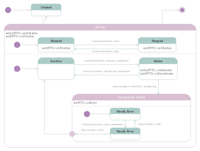
The Baseball solution for ConceptDraw DIAGRAM software contains a set of libraries, templates and samples allowing football specialists to draw baseball diagrams with ease. A set of predesigned fields and positions allows producing baseball diagrams without any drawing experience."RT-middleware (Robotics Technology Middleware) is a common platform standards for Robots based on the distributed object technology. RT-middleware supports the construction of various networked robotic systems by the integration of various network enabled robotic elements called RT-Components. The specification standard of the RT-component is discussed / defined by the Object Management Group (OMG). ...
In the RT-middleware, robotics elements, such as actuators, are regarded as RT-components, and the whole robotic system is constructed by connecting those RT-components. This distributed architecture helps developers to re-use the robotic elements, and boosts the reliability of the robotic system.
Each RT-component has port as an endpoint for communicating other RT-components. Every port has its type and the ports which have the same type can be connected each other.
RT-components also has its state, so the RT-components behaves as state machines. The states that RT-components can have are CREATED, INACTIVE, ACTIVE, and ERROR, and the states and behaviors are controlled by the execution-context. If developers want to change the behavior of their RT-components, the execution-context can be replaced at run-time." [RT middleware. Wikipedia]
The UML state machine diagram example "State transitions of RT-component" was created using the ConceptDraw PRO diagramming and vector drawing software extended with the Rapid UML solution from the Software Development area of ConceptDraw Solution Park.
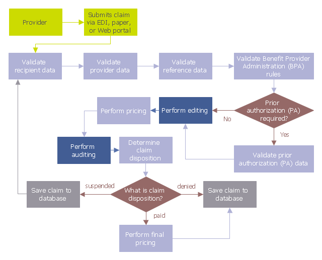
This audit flowchart sample was created on the base of the figure illustrating the webpage "Introduction to Claims Edits, Audits, Error Status Codes, and EOBs" from the website of the Ohio Department of Medicaid.
"Process.
As claims are submitted and processed, the data on the claim is validated against a series of rules, edits, and audits. Review the flowchart below to follow the sequence in which claim data is processed to see where edits and audits impact the claim adjudication process." [medicaid.ohio.gov/ PROVIDERS/ MITS/ MITSNonProviderCommunications/ MITSOnlineTutorials/ IntroductiontoClaimsEdits,Audits.aspx]
The audit flowchart example "Claim data processing" was created using the ConceptDraw PRO diagramming and vector drawing software extended with the Audit Flowcharts solution from the Finance and Accounting area of ConceptDraw Solution Park.
www.conceptdraw.com/ solution-park/ finance-audit-flowcharts
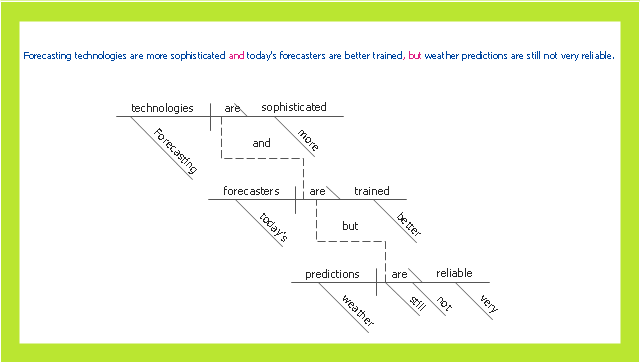
This sentence diagram sample was createb on the base of the webpage "Diagramming Sentences" from the website of the Capital Community College, Hartford CT. [grammar.ccc.commnet.edu/ grammar/ diagrams2/ one_ pager2.htm]
"In grammar, clause structure refers to the classification of sentences based on the number and kind of clauses in their syntactic structure. Such division is an element of traditional grammar.
A simple sentence consists of only one clause. A compound sentence consists of two or more independent clauses. A complex sentence has at least one independent clause plus at least one dependent clause.
A sentence consisting of one or more dependent clauses plus two or more independent clauses may be called a complex-compound sentence or compound-complex sentence. ...
A compound sentence is composed of at least two independent clauses. It does not require a dependent clause. The clauses are joined by a coordinating conjunction (with or without a comma), a semicolon that functions as a conjunction, a colon instead of a semicolon between two sentences when the second sentence explains or illustrates the first sentence and no coordinating conjunction is being used to connect the sentences, or a conjunctive adverb preceded by a semicolon. A conjunction can be used to make a compound sentence. Conjunctions are words such as for, and, nor, but, or, yet, so (the first letters of which spell "fanboys"). The use of a comma to separate two independent clauses without the addition of an appropriate conjunction is called a comma splice and is generally considered an error (when used in the English language)." [Sentence clause structure. Wikipedia]
The example "Compound sentence" was created using the ConceptDraw PRO diagramming and vector drawing software extended with the Language Learning solution from the Science and Education area of ConceptDraw Solution Park.
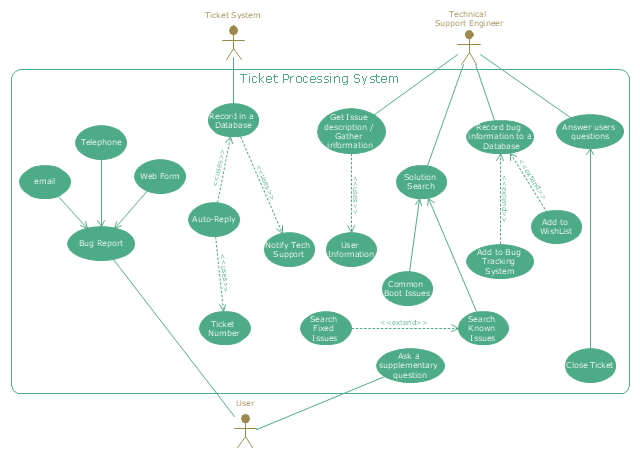
"An example scenario is presented to demonstrate how a common issue tracking system would work:
(1) A customer service technician receives a telephone call, email, or other communication from a customer about a problem. Some applications provide built-in messaging system and automatic error reporting from exception handling blocks.
(2) The technician verifies that the problem is real, and not just perceived. The technician will also ensure that enough information about the problem is obtained from the customer. This information generally includes the environment of the customer, when and how the issue occurs, and all other relevant circumstances.
(3) The technician creates the issue in the system, entering all relevant data, as provided by the customer.
(4) As work is done on that issue, the system is updated with new data by the technician. Any attempt at fixing the problem should be noted in the issue system. Ticket status most likely will be changed from open to pending.
(5) After the issue has been fully addressed, it is marked as resolved in the issue tracking system.
If the problem is not fully resolved, the ticket will be reopened once the technician receives new information from the customer. A Run Book Automation process that implements best practices for these workflows and increases IT personnel effectiveness is becoming very common." [Issue tracking system. Wikipedia]
The UML use case diagram example "Ticket processing system" was created using the ConceptDraw PRO diagramming and vector drawing software extended with the Rapid UML solution from the Software Development area of ConceptDraw Solution Park.
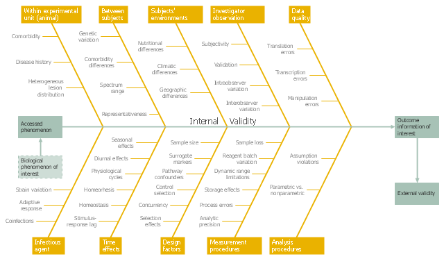
This example was created on the base of the figure from the website of the WSU College of Veterinary Medicine of the Washington State University. [vetmed.wsu.edu/ courses-jmgay/ images/ Ishikawa%20 Variance%20 Diagram.jpg]
"Internal validity is a property of scientific studies which reflects the extent to which a causal conclusion based on a study is warranted. Such warrant is constituted by the extent to which a study minimizes systematic error (or 'bias')." [Internal validity. Wikipedia]
The fishbone diagram example "Ishikawa variance diagram" was created using the ConceptDraw PRO diagramming and vector drawing software extended with the Fishbone Diagrams solution from the Management area of ConceptDraw Solution Park.
- Error message
- Error message - two commit buttons
- Events BPMN 1.2 - Vector stencils library | Design elements - Events ...
- Messages - Vector stencils library | UML Sequence Diagram. Design ...
- Design elements - Events BPMN 2.0 | Events - Vector stencils library ...
- Events - Vector stencils library
- Events BPMN 1.2 - Vector stencils library | PM Docs | Design ...
- Events BPMN 1.2 - Vector stencils library | How to Edit a Project ...
- Events BPMN 1.2 - Vector stencils library | Design elements - Events ...
- Events BPMN 1.2 - Vector stencils library | Basic Flowchart Symbols ...
- Computer pictograms - Vector stencils library | Events BPMN 1.2 ...
- Events - Vector stencils library | Design elements - Events BPMN 2.0 ...
- Events BPMN 1.2 - Vector stencils library | Expanded objects BPMN ...
- Events BPMN 1.2 - Vector stencils library | Business process model ...
- Activities BPMN 1.2 - Vector stencils library | Design elements ...
- Events - Vector stencils library | People pictograms - Vector stencils ...
- Design elements - Stratification diagram | Stratification diagram ...
- Design elements - Events BPMN 2.0 | Design elements - Gateways ...
- Window elements - Vector stencils library | Window elements ...


