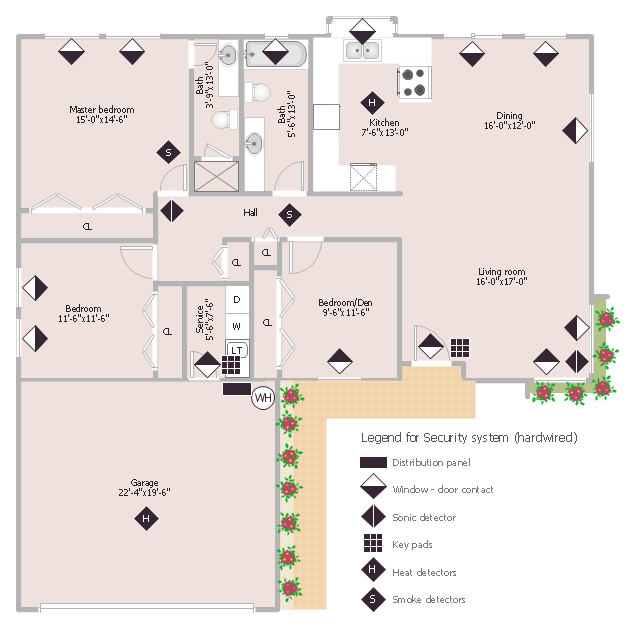
This sample was created on the base of the floor plan with security system device symbols from the website of the California State University, Sacramento. [imet.csus.edu/ imet1/ denyer/ mhs_ denyer/ drafting/ arch_ ch_ 31/ 31-28.jpg]
Legend for the security system hardware includes distribution panel, window-door contact, sonic detector, key pads, heat detectors, smoke detectors.
The example "Security system floor plan" was created using the ConceptDraw PRO diagramming and vector drawing software extended with the Security and Access Plans solution from the Building Plans area of ConceptDraw Solution Park.
The vector stencils library "Network layout floorplan" contain 34 symbol icons for drawing computer network floor plans, communication equipment layouts, and structured cabling diagrams.
"Structured cabling is building or campus telecommunications cabling infrastructure that consists of a number of standardized smaller elements (hence structured) called subsystems. ...
Structured cabling design and installation is governed by a set of standards that specify wiring data centers, offices, and apartment buildings for data or voice communications using various kinds of cable, most commonly category 5e (CAT-5e), category 6 (CAT-6), and fibre optic cabling and modular connectors. These standards define how to lay the cabling in various topologies in order to meet the needs of the customer, typically using a central patch panel (which is normally 19 inch rack-mounted), from where each modular connection can be used as needed. Each outlet is then patched into a network switch (normally also rack-mounted) for network use or into an IP or PBX (private branch exchange) telephone system patch panel." [Structured cabling. Wikipedia]
The design elements example "Network layout floorplan - Vector stencils library" was created using the ConceptDraw PRO diagramming and vector drawing software extended with the Network Layout Floor Plans solution from the Computer and Networks area of ConceptDraw Solution Park.
Create Floor Plans Easily with ConceptDraw DIAGRAM
How to create Floor Plan Design easy and effectively? You can invite an interior designer and trust this work to him, which is usually expensive and result may not always meet your expectations. Another way is to design it yourself, but at this case you need to have special skills, knowledges and abilities, among them basic knowledge of the composition rules, color theory, materials science and software for interior design development. The ability to use specialized software for drawing is especially valuable, useful and saves your time. ConceptDraw DIAGRAM is one of the best among similar software, it offers extensive functionality, powerful tools, a lot of features, and is simple for using, so can be applied by everyone without efforts. Enhanced with Floor Plans and other solutions from the Building Plans area, the ConceptDraw DIAGRAM software helps easily create unique and harmonious interior designs, and draw in desired scale professional-looking Floor Plans and Layouts for homes, apartments, hotels, offices, and other buildings. ConceptDraw DIAGRAM is a full Visio compatibility and better alternative for students, teachers and business professionals to reliably create kinds of flowcharts, organizational charts, network diagrams, floor plans, electrical diagrams, software design diagrams, maps and more.
"The Ethernet physical layer is the physical layer component of the Ethernet family of computer network standards.
The Ethernet physical layer evolved over a considerable time span and encompasses quite a few physical media interfaces and several magnitudes of speed. The speed ranges from 1 Mbit/ s to 100 Gbit/ s, while the physical medium can range from bulky coaxial cable to twisted pair and optical fiber. In general, network protocol stack software will work similarly on all physical layers.
10-gigabit Ethernet was already used in both enterprise and carrier networks by 2007, with 40 Gbit/ s and 100 Gbit/ s Ethernet ratified. ...
Many Ethernet adapters and switch ports support multiple speeds, using autonegotiation to set the speed and duplex for the best values supported by both connected devices. If auto-negotiation fails, a multiple-speed device will sense the speed used by its partner, but will assume half-duplex. A 10/ 100 Ethernet port supports 10BASE-T and 100BASE-TX. A 10/ 100/ 1000 Ethernet port supports 10BASE-T, 100BASE-TX, and 1000BASE-T." [Ethernet physical layer. Wikipedia]
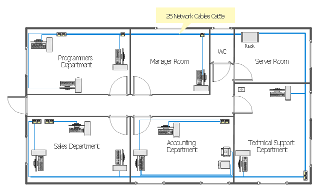
The LAN equipment and cabling layout floorplan example "Ethernet local area network layout floor plan" was created using the ConceptDraw PRO diagramming and vector drawing software extended with the Network Layout Floor Plans solution from the Computer and Networks area of ConceptDraw Solution Park.
"A fast casual restaurant is a type of restaurant that does not offer full table service, but promises a higher quality of food and atmosphere than a fast food restaurant. In the US, it is a relatively new and growing concept positioned between fast food and casual dining." [Fast casual restaurant. Wikipedia]
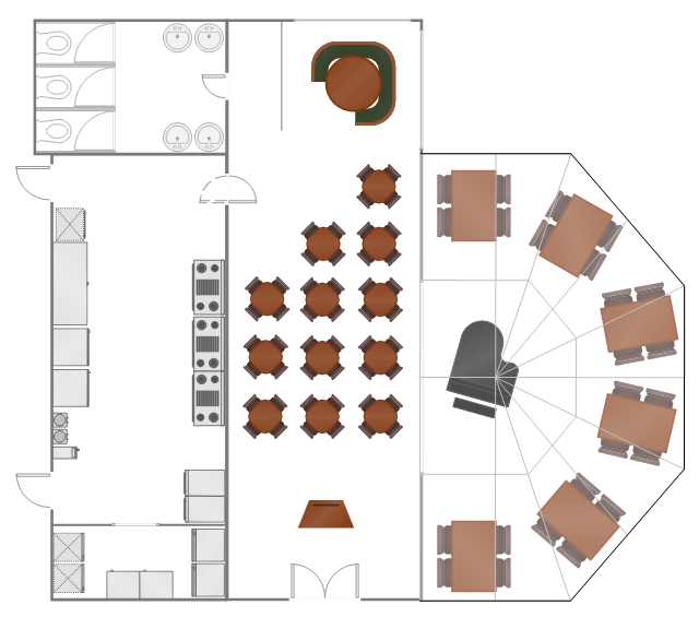
The example "Restaurant floor plan" was created using the ConceptDraw PRO diagramming and vector drawing software extended with the Cafe and Restaurant solution from the Building Plans area of ConceptDraw Solution Park.
The example "Restaurant floor plan" was created using the ConceptDraw PRO diagramming and vector drawing software extended with the Cafe and Restaurant solution from the Building Plans area of ConceptDraw Solution Park.
This interior design sample depicts the layout of equipment, furniture and appliances on the gym floor plan.
"Exercise equipment is any apparatus or device used during physical activity to enhance the strength or conditioning effects of that exercise by providing either fixed or adjustable amounts of resistance, or to otherwise enhance the experience or outcome of an exercise routine.
Exercise equipment may also include such items as proper footgear, gloves, hydration equipment, etc.
It is important to use exercise equipment properly: inappropriate use of equipment can lead to injuries from mild to extreme." [Exercise equipment. Wikipedia]
The interior design example "Gym equipment layout floor plan" was created using the ConceptDraw PRO diagramming and vector drawing software extended with the Gym and Spa Area Plans solution from the Building Plans area of ConceptDraw Solution Park.
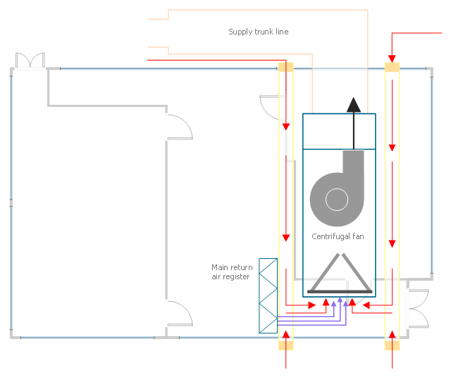
This HVAC plan sample shows the air handler layout on the floor plan.
"An air handler, or air handling unit (often abbreviated to AHU), is a device used to condition and circulate air as part of a heating, ventilating, and air-conditioning (HVAC) system. An air handler is usually a large metal box containing a blower, heating or cooling elements, filter racks or chambers, sound attenuators, and dampers. Air handlers usually connect to a ductwork ventilation system that distributes the conditioned air through the building and returns it to the AHU. Sometimes AHUs discharge (supply) and admit (return) air directly to and from the space served without ductwork.
Small air handlers, for local use, are called terminal units, and may only include an air filter, coil, and blower; these simple terminal units are called blower coils or fan coil units. A larger air handler that conditions 100% outside air, and no recirculated air, is known as a makeup air unit (MAU). An air handler designed for outdoor use, typically on roofs, is known as a packaged unit (PU) or rooftop unit (RTU)." [Air handler. Wikipedia]
The floor plan example "Air handler - HVAC plan" was created using the ConceptDraw DIAGRAM diagramming and vector drawing software extended with the HVAC Plans solution from the Building Plans area of ConceptDraw Solution Park.
This cafe electrical floor plan sample shows the outlet and switch layout.
"An electrical drawing, is a type of technical drawing that shows information about power, lighting, and communication for an engineering or architectural project. Any electrical working drawing consists of "lines, symbols, dimensions, and notations to accurately convey an engineering's design to the workers, who install the electrical system on the job".
A complete set of working drawings for the average electrical system in large projects usually consists of:
(1) A plot plan showing the building's location and outside electrical wiring.
(2) Floor plans showing the location of electrical systems on every floor.
(3) Power-riser diagrams showing panel boards.
(4) Control wiring diagrams.
(5) Schedules and other information in combination with construction drawings.
Electrical drafters prepare wiring and layout diagrams used by workers who erect, install, and repair electrical equipment and wiring in communication centers, power plants, electrical distribution systems, and buildings." [Electrical drawing. Wikipedia]
The outlet and switch layout example "Cafe electrical floor plan" was created using the ConceptDraw PRO diagramming and vector drawing software extended with the Electric and Telecom Plans solution from the Building Plans area of ConceptDraw Solution Park.
How to create Cafe Floor Plan Design
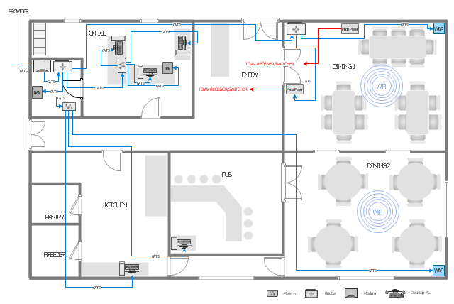
Cafes and restaurants are the premises, the main purpose of which is to organize the proper rest of persons. The basis for successful development of this business is the good mood of visitors that is formed under the influence of many factors including the pleasant design and interior of the cafe, its color solution, style, decoration elements, lighting, furniture, etc. That is why so many demands are presented to the style, design and decoration of the cafe, the main are originality, comfort and convenience of each guest. The cafe's interior design should be fully completed, every item and accessory should harmoniously supplement the overall interior picture. The competent approach and strict observance of all recommendations the specialists on planning and arrangement of cafe are very important, they guarantee the success of your institution. ConceptDraw DIAGRAM enhanced with powerful Cafe and Restaurant Floor Plan solution is easy-to-use cafe floor plan design software, which helps effectively develop Cafe designs, Cafe and Restaurant floor plans and layouts of any complexity.This computer network layout floorplan was drawn on the base of the picture from the Media Institute blog of the Madison Media Institute.
[mediainstitute.edu/ media-schools-blog/ wp-content/ uploads/ 2012/ 01/ floor_ plan.png]
The example "Restaurant network layout floorplan" was created using the ConceptDraw PRO diagramming and vector drawing software extended with the Network Layout Floor Plans solution from the Computer and Networks area of ConceptDraw Solution Park.
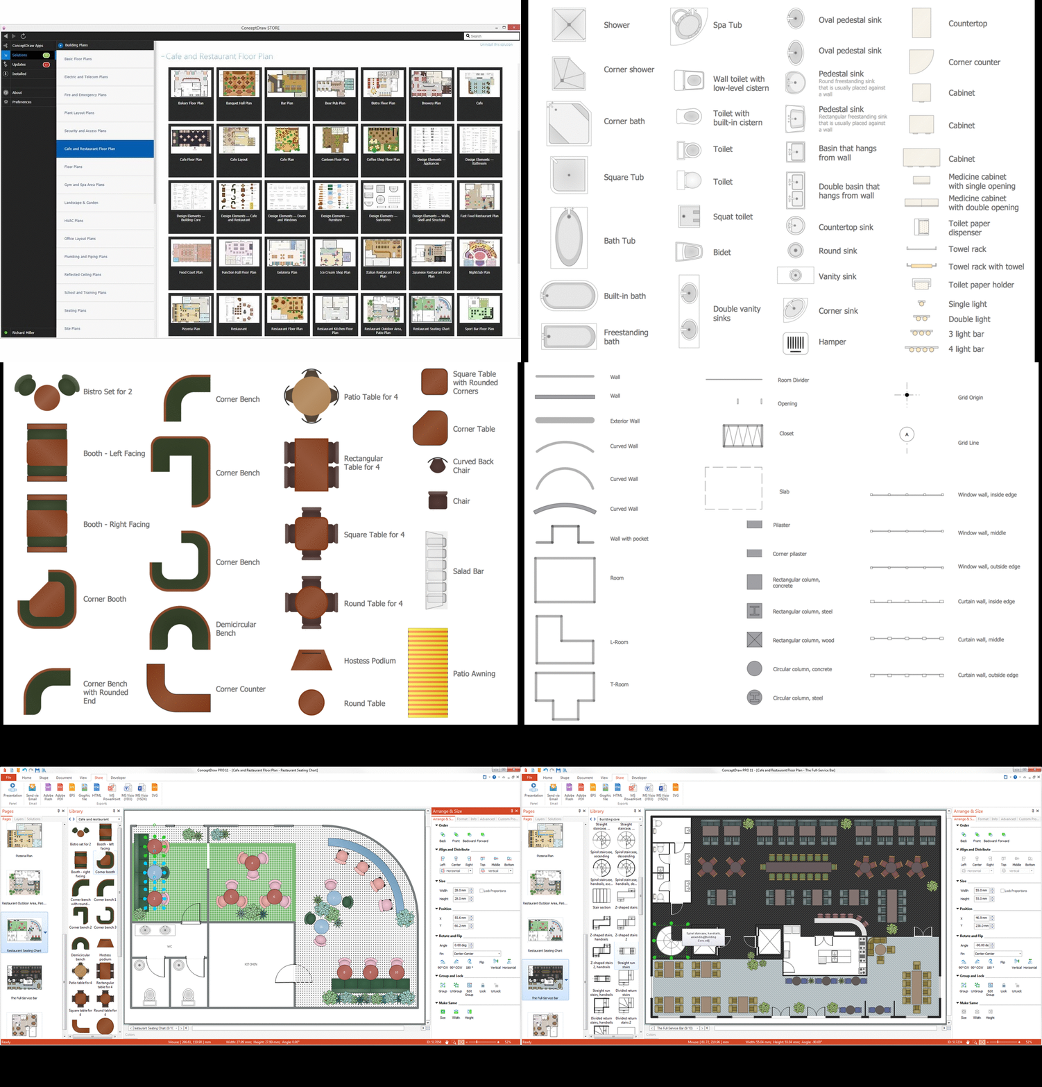
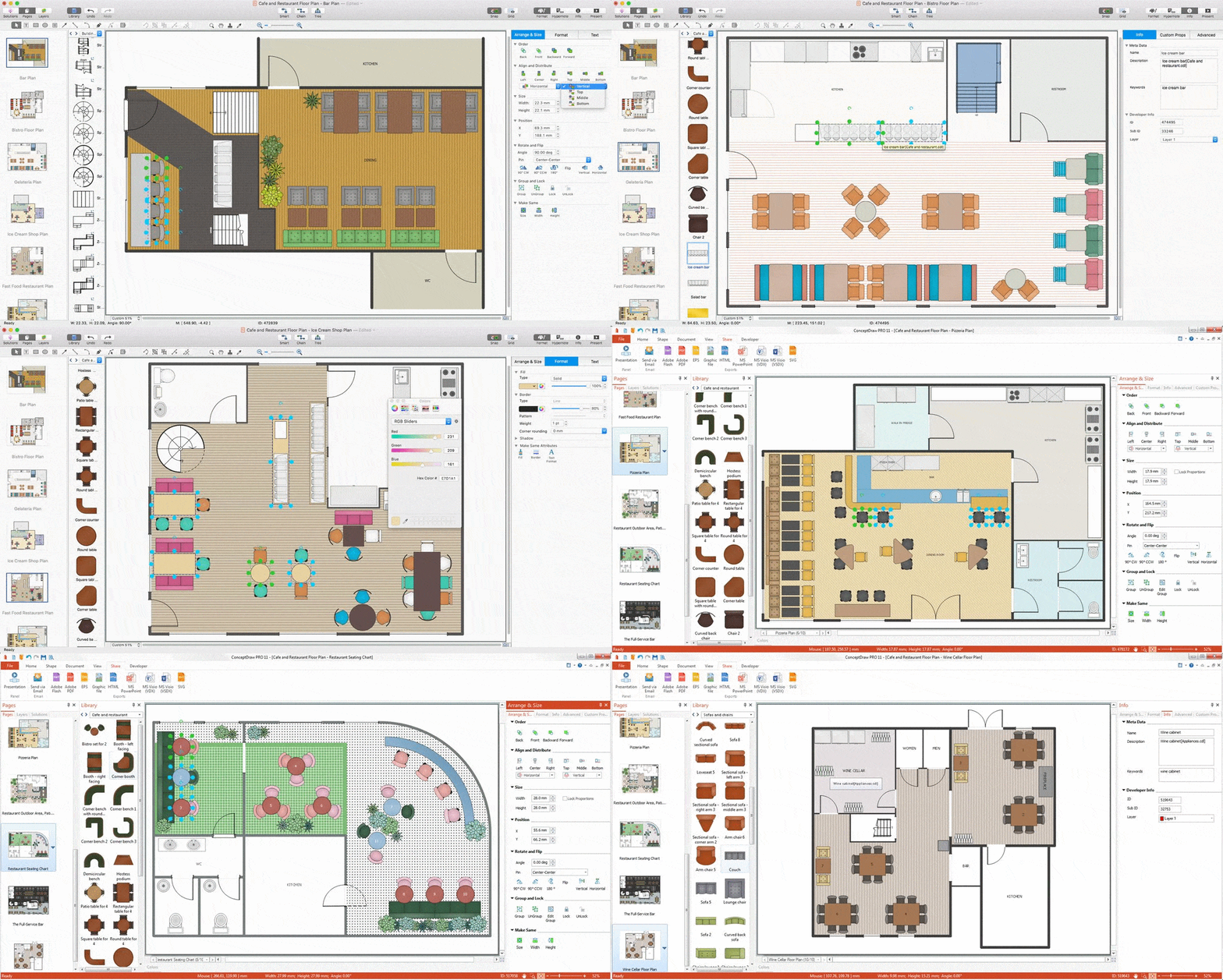
Restaurant Floor Plan Software
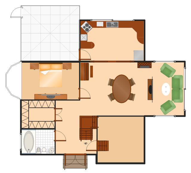
The restaurant is a beautiful place for relax and recreation. But not all the restaurants are popular. What is the secret of popularity and active visiting of some restaurant? People pay special attention for design and atmosphere, they must be pleasant and unique. All design elements, correct planning and furniture layout, location of the main hall and kitchen, beautiful music and good service, delicious dishes, create an unforgettable atmosphere of comfort, harmony, and convenience. Having a powerful ConceptDraw DIAGRAM software extended with Cafe and Restaurant Plans solution from Building Plans Area of ConceptDraw Solution Park, you can create your unique and successful Restaurant Floor plans, Restaurant layouts, and Restaurant designs in a few minutes. This solution includes a lot of Restaurant floor plan samples, examples, templates, and variety of libraries with professionally designed vector objects of different furniture, appliances, and other restaurant design elements helpful for fast and easy drawing Floor plan of restaurant.This interior design sample shows the layout of furniture, kitchen and bathroom appliances on the house floor plan.
"A house is a building that functions as a home for humans or other creatures, including simple dwellings ranging from rudimentary huts of nomadic tribes and complex structures composed of many systems.
The social unit that lives in a house is known as a household. Most commonly, a household is a family unit of some kind, although households may also be other social groups or individuals.
Ideally, architects of houses design rooms to meet the needs of the people who will live in the house. Such designing, known as "interior design", has become a popular subject in universities." [House. Wikipedia]
The example "House floor plan" was created using the ConceptDraw PRO diagramming and vector drawing software extended with the Floor Plans solution from the Building Plans area of ConceptDraw Solution Park.
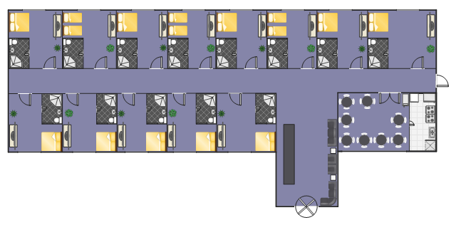
This example depicts furniture and home appliances layout on the hotel floor plan.
"A hotel is an establishment that provides lodging paid on a short-term basis. The provision of basic accommodation, in times past, consisting only of a room with a bed, a cupboard, a small table and a washstand has largely been replaced by rooms with modern facilities, including en-suite bathrooms and air conditioning or climate control. Additional common features found in hotel rooms are a telephone, an alarm clock, a television, a safe, a mini-bar with snack foods and drinks, and facilities for making tea and coffee. Luxury features include bathrobes and slippers, a pillow menu, twin-sink vanities, and jacuzzi bathtubs. Larger hotels may provide additional guest facilities such as a swimming pool, fitness center, business center, childcare, conference facilities and social function services." [Hotel. Wikipedia]
The example "Hotel floor plan" was created using the ConceptDraw PRO diagramming and vector drawing software extended with the Floor Plans solution from the Building Plans area of ConceptDraw Solution Park.
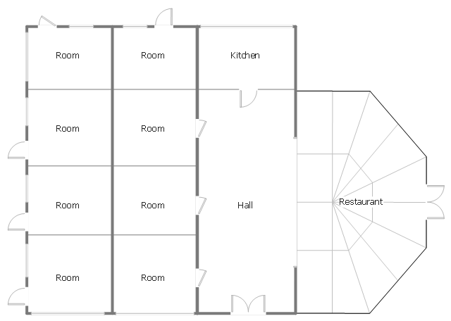
This architectural drawing sample represent hall, rooms, restaurant and kitchen layout on the minihotel floor plan.
"Small to medium-sized hotel establishments that offer a very limited amount of on-site amenities and often only offer basic accommodations with little to no services, these facilities normally only cater and market to a specific demographic of travelers, such as the budget-minded traveler seeking a "no frills" accommodation. Limited service hotels often lack an on-site restaurant but in return may offer a limited complimentary food and beverage amenity such as on-site continental breakfast service." [Hotel. Wikipedia]
The architectural drawing example "Minihotel floor plan" was created using the ConceptDraw PRO diagramming and vector drawing software extended with the Floor Plans solution from the Building Plans area of ConceptDraw Solution Park.
The vector stencils library "Network layout floorplan" contain 34 symbol icons for drawing computer network floor plans and communication equipment and cabling layouts.
"Networking hardware may also be known as network equipment or computer networking devices. Units which are the last receiver or generate data are called hosts or data terminal equipment.
All these terms refer to devices facilitating the use of a computer network. Specifically, they mediate data in a computer network. ...
Typically, networking hardware includes gateways, routers, network bridges, switches, hubs, and repeaters. But it also includes hybrid network devices such as multilayer switches, protocol converters, bridge routers, proxy servers, firewalls, network address translators, multiplexers, network interface controllers, wireless network interface controllers, modems, ISDN terminal adapters, line drivers, wireless access points, networking cables and other related hardware.
The most common kind of networking hardware today is a copper-based Ethernet adapter because of its standard inclusion on most modern computer systems. Wireless networking has, however, become increasingly popular, especially for portable and handheld devices.
Other hardware prevalent in computer networking includes data center equipment (such as file servers, database servers and storage areas), network services (such as DNS, DHCP, email, etc.) as well as devices which assure content delivery." [Networking hardware. Wikipedia]
The shapes example "Design elements - Network layout floorplan" was created using the ConceptDraw PRO diagramming and vector drawing software extended with the Network Layout Floor Plans solution from the Computer and Networks area of ConceptDraw Solution Park.
- Design elements - Doors and windows | Gym layout plan | Hotel ...
- Reflected ceiling plan layout | Lecture theatre floor plan | Home floor ...
- Security system floor plan | Design elements - Doors and windows ...
- Design elements - Doors and windows | Security system floor plan ...
- Home floor plan template | Design elements - Doors and windows ...
- Flat design floor plan | Classroom floor plan | Rolling Door And ...
- Security system floor plan | Windows 8 User Interface | How to Plan ...
- Creative classroom floor plan | Classroom furniture and equipment ...
- Window Symbol Floor Plan
- Home floor plan template | Doors - Vector stencils library | Room ...
- Doors Vector Plan
- Network Layout Floor Plans | Ethernet local area network layout floor ...
- Air handler- HVAC plan | Security system floor plan | Plumbing ...
- Gym equipment layout floor plan
- Cafe electrical floor plan | Symbol Of Double Hung Door
- Network Layout Floor Plans | Design elements - Network layout ...
- How to Draw a Security and Access Floor Plan | Network Layout ...
- Security system floor plan | Air handler- HVAC plan | Office wireless ...
- How to Create a Floor Plan for the Classroom | Classroom Seating ...
- Floor Plan Symbol For Slding Glass Doors
