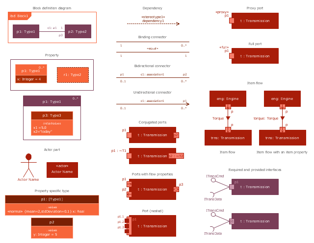
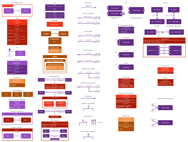
The vector stencils library "Internal block diagram" contains 22 SysML symbols.
Use it to design your internal block diagrams using ConceptDraw PRO diagramming and vector drawing software.
"Internal Block Diagram
An internal block diagram is based on the UML composite structure diagram, with restrictions and extensions as defined
by SysML. ...
Property types
Four general categories of properties of blocks are recognized in SysML: parts, references, value properties, and
constraint properties. ... A part or value property is always shown on an internal block diagram with a solid-outline box. A reference property is shown by a dashed-outline box, consistent with UML. Ports are special cases of properties, and have a variety of notations... Constraint properties and their parameters also have their own notations... " [www.omg.org/ spec/ SysML/ 1.3/ PDF]
The SysML shapes example "Design elements - Internal block diagram" is included in the SysML solution from the Software Development area of ConceptDraw Solution Park.
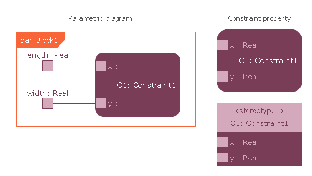
The vector stencils library "Parametric diagram" contains 3 SysML symbols.
Use it to design your parametric diagrams using ConceptDraw PRO diagramming and vector drawing software.
"A parametric diagram is defined as a restricted form of internal block diagram. A parametric diagram may contain
constraint properties and their parameters, along with other properties from within the internal block context. All
properties that appear, other than the constraints themselves, must either be bound directly to a constraint parameter, or contain a property that is bound to one (through any number of levels of containment)." [www.omg.org/ spec/ SysML/ 1.3/ PDF]
The SysML shapes example "Design elements - Parametric diagram" is included in the SysML solution from the Software Development area of ConceptDraw Solution Park.
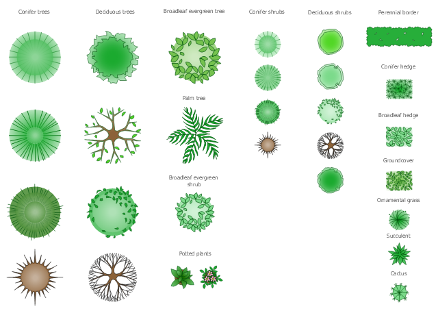
The design elements library Trees and plants contains 29 symbols of trees, hedges, groundcovers, greenery, and shrubbery.
"Landscape design is an independent profession and a design and art tradition, practised by landscape designers, combining nature and culture. In contemporary practice landscape design bridges between landscape architecture and garden design.
Landscape design focuses on both the integrated master landscape planning of a property and the specific garden design of landscape elements and plants within it." [Landscape design. Wikipedia]
Use the vector stencils library Trees and plants to draw the plans of landscape architecture, lawns, gardens, yards, parks planning, groundskeeping, landscape design, and arboretums using the ConceptDraw PRO diagramming and vector drawing software.
The shapes library Trees and plants is contained in the Site Plans solution from the Building Plans area of ConceptDraw PRO Solution Park.
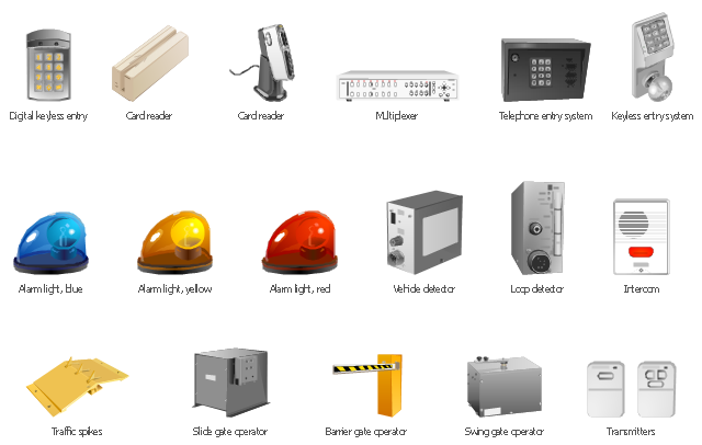
The vector clipart library Access and security contains 17 images of access control and security system equipment.
"In the fields of physical security and information security, access control is the selective restriction of access to a place or other resource. The act of accessing may mean consuming, entering, or using. Permission to access a resource is called authorization.
Locks and login credentials are two analogous mechanisms of access control. ...
The term access control refers to the practice of restricting entrance to a property, a building, or a room to authorized persons. Physical access control can be achieved by a human (a guard, bouncer, or receptionist), through mechanical means such as locks and keys, or through technological means such as access control systems like the mantrap. Within these environments, physical key management may also be employed as a means of further managing and monitoring access to mechanically keyed areas or access to certain small assets." [Access control. Wikipedia]
Use the vector stencils library Access and security to draw illustrations and diagrams of safety and security system equipment using the ConceptDraw PRO diagramming and vector drawing software.
The clipart example "Design elements - Access and security" is included in the Safety and Security solution from the Illustration area of ConceptDraw Solution Park.
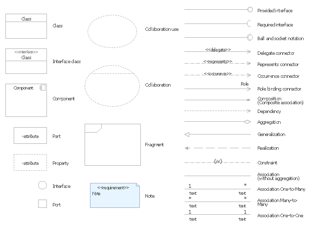
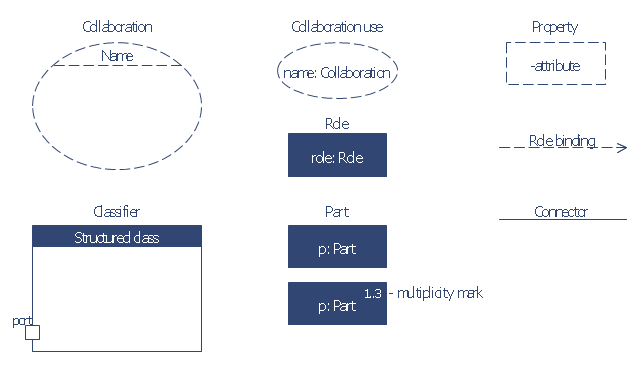
The vector stencils library "UML composite structure diagrams" contains 36 symbols for the ConceptDraw PRO diagramming and vector drawing software.
"The key composite structure entities identified in the UML 2.0 specification are structured classifiers, parts, ports, connectors, and collaborations.
(1) Part : A part represents a role played at runtime by one instance of a classifier or by a collection of instances. The part may only name the role, it may name an abstract superclass, or it may name a specific concrete class. The part can include a multiplicity factor, such as the [0..*] shown for Viewer in the diagram.
(2) Port : A port is an interaction point that can be used to connect structured classifiers with their parts and with the environment. Ports can optionally specify the services they provide and the services they require from other parts of the system. In the diagram, each of the small squares is a port. Each port has a type and is labelled with a name, such as "var", "indVar1", or "view" in the diagram. Ports may contain a multiplicity factor, for example.
Ports can either delegate received requests to internal parts, or they can deliver these directly to the behavior of the structured classifier that the port is contained within. Public ports that are visible in the environment are shown straddling the boundary, while protected ports that are not visible in the environment are shown inside the boundary. All the ports in the diagram are public, except for the view port along the right boundary of FibonacciSystem.
(3) Connector : A connector binds two or more entities together, allowing them to interact at runtime. The connector is shown as a line between some combination of parts, ports and structured classifiers. The diagram shows three connectors between ports, and one connector between a structured classifier and a part.
(4) Collaboration : A collaboration is generally more abstract than a structured classifier. It is shown as a dotted oval containing roles that instances can play in the collaboration.
(5) Structured classifier : A StructuredClassifier represents a class, often an abstract class, whose behavior can be completely or partially described through interactions between parts." [Composite structure diagram. Wikipedia]
The example "Design elements - UML composite structure diagrams" is included in the Rapid UML solution from the Software Development area of ConceptDraw Solution Park.
The vector stencils library "Bank UML composite structure diagram" contains 10 shapes for drawing UML composite structure diagrams.
Use it for object-oriented modeling of your bank information system.
"The key composite structure entities identified in the UML 2.0 specification are structured classifiers, parts, ports, connectors, and collaborations.
* Part : A part represents a role played at runtime by one instance of a classifier or by a collection of instances. The part may only name the role, it may name an abstract superclass, or it may name a specific concrete class. The part can include a multiplicity factor, such as the [0..*] shown for Viewer in the diagram.
* Port : A port is an interaction point that can be used to connect structured classifiers with their parts and with the environment. Ports can optionally specify the services they provide and the services they require from other parts of the system. In the diagram, each of the small squares is a port. Each port has a type and is labelled with a name... in the diagram. Ports may contain a multiplicity factor...
* Connector : A connector binds two or more entities together, allowing them to interact at runtime. The connector is shown as a line between some combination of parts, ports and structured classifiers. The diagram shows three connectors between ports, and one connector between a structured classifier and a part.
* Collaboration : A collaboration is generally more abstract than a structured classifier. It is shown as a dotted oval containing roles that instances can play in the collaboration.
* Structured classifier: A StructuredClassifier represents a class, often an abstract class, whose behavior can be completely or partially described through interactions between parts.
An EncapsulatedClassifier is a type of structured classifier that contains ports." [Composite structure diagram. Wikipedia]
This example of UML composite structure diagram symbols for the ConceptDraw PRO diagramming and vector drawing software is included in the ATM UML Diagrams solution from the Software Development area of ConceptDraw Solution Park.
The vector stencils library "Block definition diagram" contains 54 SysML symbols.
Use it to design your block definition diagrams using ConceptDraw PRO diagramming and vector drawing software.
"Block Definition Diagram
A block definition diagram is based on the UML class diagram, with restrictions and extensions as defined by SysML. ...
Block and ValueType Definitions
A SysML Block defines a collection of features to describe a system or other element of interest. A SysML ValueType
defines values that may be used within a model. SysML blocks are based on UML classes, as extended by UML composite structures. SysML value types are based on UML data types. Diagram extensions for SysML blocks and value types are described by other subheadings of this sub clause." [www.omg.org/ spec/ SysML/ 1.3/ PDF]
The SysML shapes example "Design elements - Block definition diagram" is included in the SysML solution from the Software Development area of ConceptDraw Solution Park.
The vector stencils library "Electrical circuits" contains 49 element symbols of electrical and electronic devices, including ignitors, starters, transmitters, circuit protectors, transducers, radio and audio equipment.
Use it for drawing electronic circuit diagrams and electrical schematics.
"An electrical network is an interconnection of electrical elements such as resistors, inductors, capacitors, voltage sources, current sources and switches. An electrical circuit is a network consisting of a closed loop, giving a return path for the current. Linear electrical networks, a special type consisting only of sources (voltage or current), linear lumped elements (resistors, capacitors, inductors), and linear distributed elements (transmission lines), have the property that signals are linearly superimposable. They are thus more easily analyzed, using powerful frequency domain methods such as Laplace transforms, to determine DC response, AC response, and transient response.
A resistive circuit is a circuit containing only resistors and ideal current and voltage sources. Analysis of resistive circuits is less complicated than analysis of circuits containing capacitors and inductors. If the sources are constant (DC) sources, the result is a DC circuit.
A network that contains active electronic components is known as an electronic circuit. Such networks are generally nonlinear and require more complex design and analysis tools." [Electrical network. Wikipedia]
The symbils example "Design elements - Electrical circuits" was drawn using the ConceptDraw PRO diagramming and vector drawing software extended with the Electrical Engineering solution from the Engineering area of ConceptDraw Solution Park.
- Residential Property Design Software
- Building Drawing Software for Design Site Plan | How To Draw ...
- IDEF3 Standard | Object-Oriented Design | Types of Flowchart ...
- Activity Diagram Of Property Management System
- Building Drawing Software for Design Site Plan | How To use House ...
- Building Drawing Software for Design Site Plan | Table Seating ...
- How To Draw Building Plans | How to Add a Floor Plan to a MS ...
- Property Management Microsoft Access Flowchart
- How to Draw a Landscape Design Plan | Landscape Architecture ...
- Site Plans | Building Drawing Software for Design Site Plan ...
- How To Draw Building Plans | How To use Building Plan Examples ...
- How to Draw a Landscape Design Plan | Building Drawing Software ...
- Design Methodology On Online Property Management System
- UML Class Diagram Example - Apartment Plan | Basic Floor Plans ...
- UML Class Diagram Example - Apartment Plan | Property ...
- Building Drawing Software for Design Site Plan | How To use ...
- How To Draw Building Plans | Building Drawing Software for Design ...
- How To use Landscape Design Software | Building Drawing ...
- Design elements - Internal block diagram | UML Diagram | UML ...
