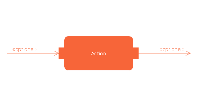
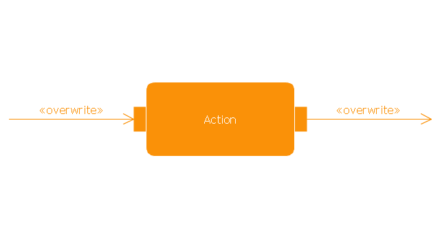
UML Activity Diagram. Design Elements
UML Activity Diagram illustrate the business and operational step-by-step workflow of components in a system and shows the overall flow of control.
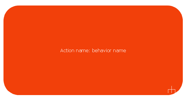
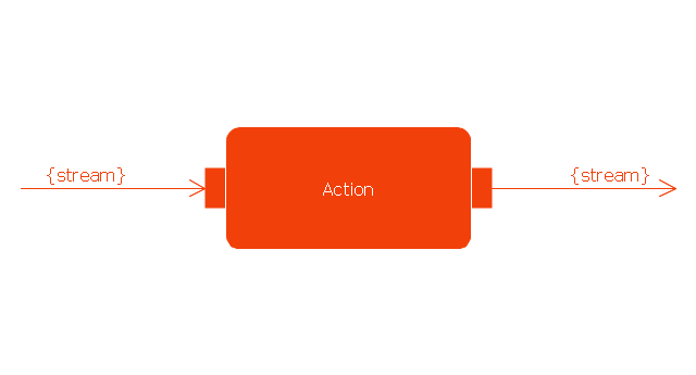
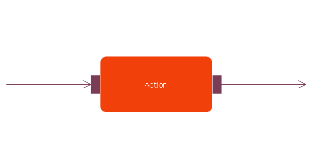
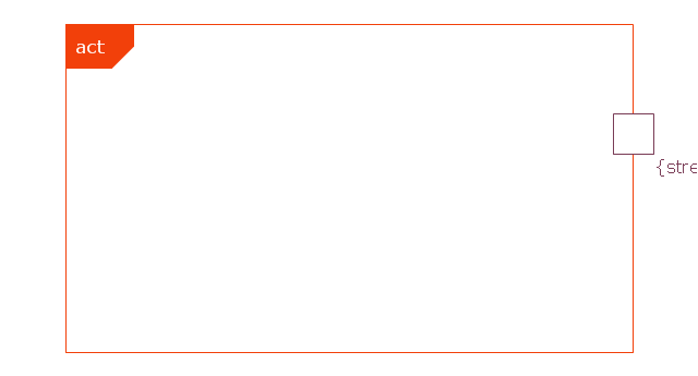
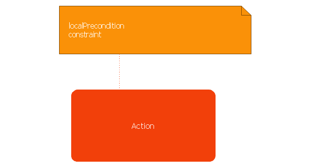
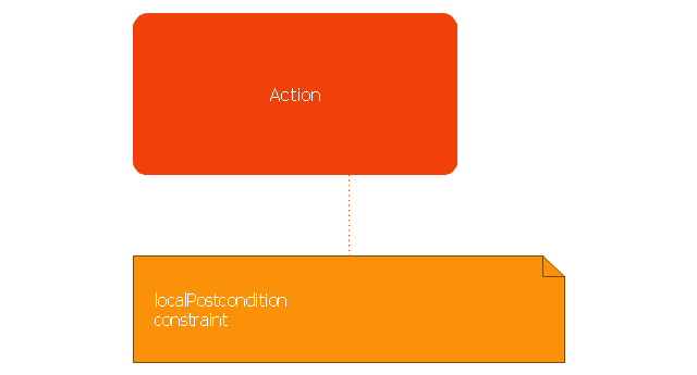
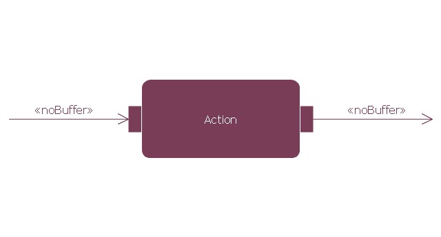
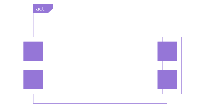
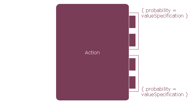
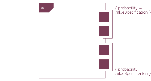
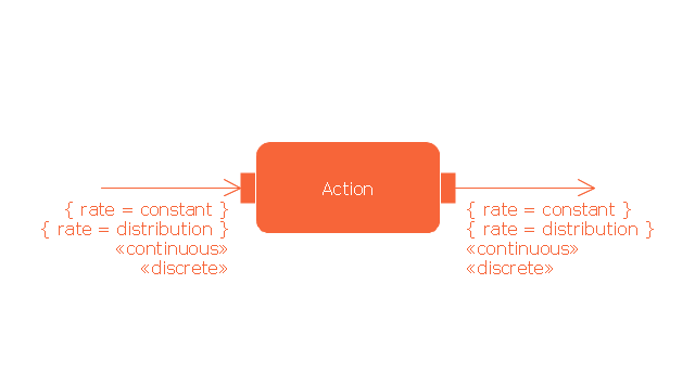
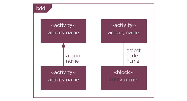
This vector stencils library contains 47 SysML activity diagram symbols.
Use it to design your SysML activity diagrams using ConceptDraw PRO diagramming and vector drawing software.
"Activity diagrams are constructed from a limited number of shapes, connected with arrows. The most important shape types:
- rounded rectangles represent actions;
- diamonds represent decisions;
- bars represent the start (split) or end (join) of concurrent activities;
- a black circle represents the start (initial state) of the workflow;
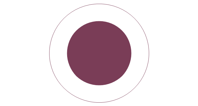
- an encircled black circle represents the end (final state).
Arrows run from the start towards the end and represent the order in which activities happen." [Activity diagram. Wikipedia]
The vector stencils library "Activity diagram" is included in the SysML solution from the Software Development area of ConceptDraw Solution Park.
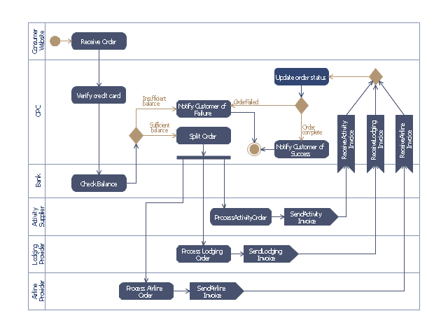
This purchase order processing UML activity diagram was created on the base of activity diagram from the software architecture documentation wiki of the Software Engineering Institute (SEI) of Carnegie Mellon University (CMU).
[wiki.sei.cmu.edu/ sad/ index.php/ Image:PurchaseOrderActivityDiagram.png]
"A purchase order (PO) is a commercial document and first official offer issued by a buyer to a seller, indicating types, quantities, and agreed prices for products or services. Acceptance of a purchase order by a seller forms a contract between the buyer and seller, so no contract exists until the purchase order is accepted. It is used to control the purchasing of products and services from external suppliers.
Creating a purchase order is typically the first step of the purchase to pay process in an ERP system." [Purchase order. Wikipedia]
This purchase order processing UML activity diagram example was created using the ConceptDraw PRO diagramming and vector drawing software extended with the ATM UML Diagrams solution from the Software Development area of ConceptDraw Solution Park.
- UML activity diagram ( swimlanes ) - Template | Design elements ...
- UML activity diagram ( swimlanes ) - Template | Design elements ...
- UML activity diagram ( swimlanes ) - Template
- Design elements - UML activity diagrams | UML Flowchart Symbols ...
- Design elements - UML activity diagrams | Cross-Functional ...
- UML Activity Diagram. Design Elements | UML interaction overview ...
- UML Activity Diagram. Design Elements | Design elements - UML ...
- UML activity diagram
- UML State Machine Diagram.Design Elements | Vector stencils ...
- UML activity diagram - Alarm trigger processing | Vector stencils ...
- UML State Machine Diagram.Design Elements | Design elements ...
- Design elements - UML use case diagrams
- Design elements - UML state machine diagrams | Design elements ...
- Design elements - Bank UML activity diagram | Process Flowchart ...
- UML Activity Diagram. Design Elements | Vector stencils library ...
- Uml Activity Diagram Vector Stencils
- UML Activity Diagram. Design Elements
- And Join
- How to Create a BPMN Diagram Using Border Events in ...
- UML State Machine Diagram.Design Elements | UML Diagram ...


