The vector stencils library "Computer network" contains 51 symbols of computer network devices and equipment for drawing computer network diagrams.
"Network Mapping Software.
A number of software tools exist to design computer network diagrams / or generate visual maps of networks, servers, storage, services, data centers, and other peripherals. Broadly, there are two types of software tools - those that help create diagrams manually and those that generate them using automated / semi-automated approaches.
Type of Software.
(1) Manual - allows users to design and draw logical and physical topology diagrams by manually placing icons and connections.
(2) Automated - generate topology diagrams / maps by traversing the network and automatically discovering resident devices or by importing network data." [Comparison of network diagram software. Wikipedia]
ConceptDraw PRO is the software for manual design of computer network diagrams. The solutions of the Computer and Networks area in ConceptDraw Solution Park extend ConceptDraw PRO with vector stencils libraries, templates and examples for creating the computer network diagrams.
The symbols example "Computer network - Vector stencils library" was created using the ConceptDraw PRO diagramming and vector drawing software extended with the Computer and Networks solution from the Computer and Networks area of ConceptDraw Solution Park.
www.conceptdraw.com/ solution-park/ computer-and-networks
Laptop

Desktop computer

Firewall

Bus

Ethernet

Star network

FDDI Ring

Token-ring

Comm-link

Modem

Laser printer

Inkjet printer

Image scanner

City

Ethernet hub

Wireless router

Network switch

iPod Classic

iPhone/ iPod Touch

Xserve RAID

XServe

Apple Thunderbolt Display

Data store

Mac Pro

iMac

RAID

Mainframe

Rack-mountable server

Server

PDA

Cloud

Computer monitor

Workstation

Router

IP Phone

Fax

Mobile phone

Smartphone

Compact Disk

Mouse

Apple Wireless Mouse

Computer keyboard

Apple Keyboard

Radio tower

Satellite dish

Satellite

Webcam

AirPort Extreme

Airport Express

MacBook

iPhone 4

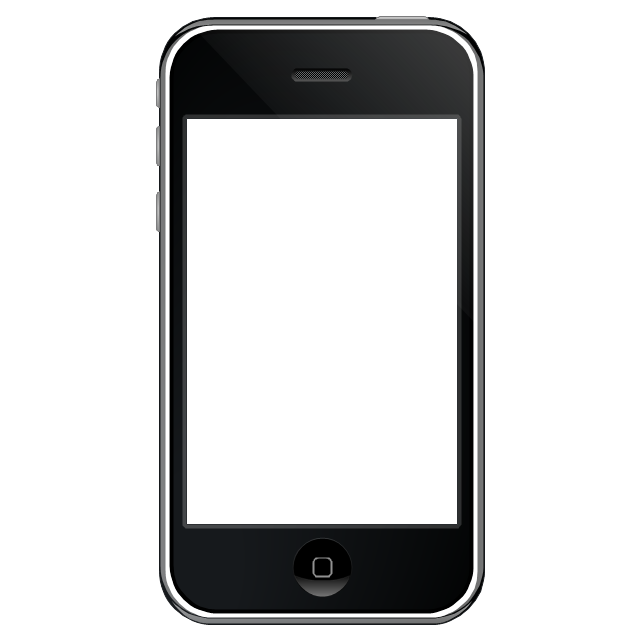
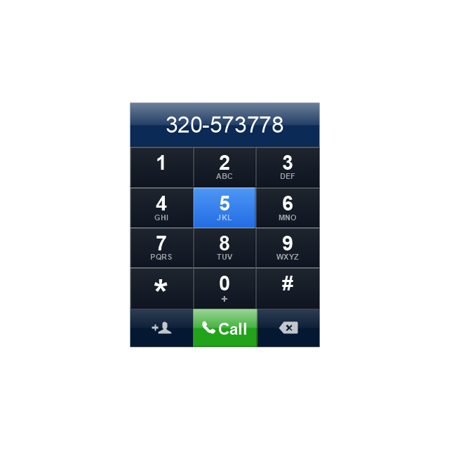
The vector stencils library "iPhone interface" contains 119 iPhone UI design elements.
Use it for development of graphic user interface (GUI) for iPhone software applications in the ConceptDraw PRO diagramming and vector drawing software extended with the Graphic User Interface solution from the Software Development area of ConceptDraw Solution Park.
Use it for development of graphic user interface (GUI) for iPhone software applications in the ConceptDraw PRO diagramming and vector drawing software extended with the Graphic User Interface solution from the Software Development area of ConceptDraw Solution Park.
iPhone case
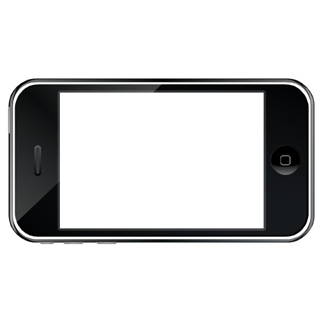
iPhone case, horizontal
Display
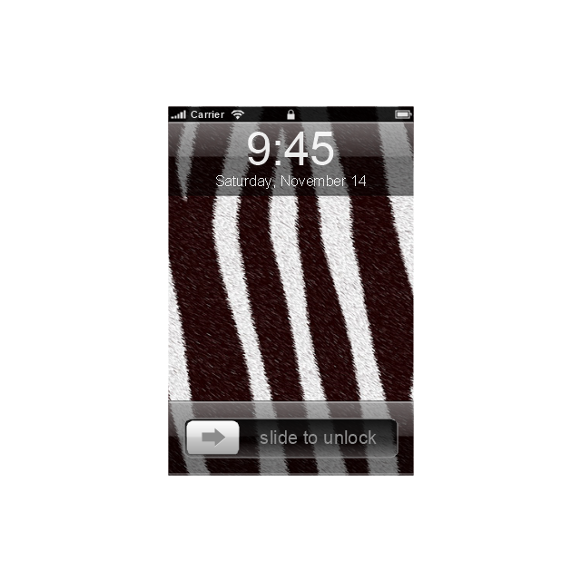
Screen

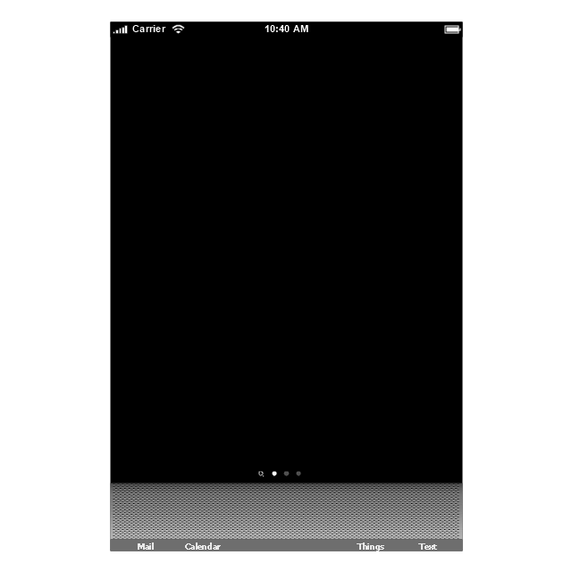
Home screen
Keypad control
Status bar
Navigation bar
Navigation bar with buttons
Navigation bar with controls
Navigation bar with controls
Navigation bar with buttons, horizontal
Navigation bar with controls, horizontal
Modal view
Search bar
Text field 1

Text field 2

Text field, varying
Table row
Table view row
Table view (simple list)
-iphone-interface---vector-stencils-library.png--diagram-flowchart-example.png)
Table view (with header)
-iphone-interface---vector-stencils-library.png--diagram-flowchart-example.png)
Action list
Control button
Navigational control button

Add button
Navigation toolbar

Tab bar

Action sheet

Choice button
Rounded rectangle button
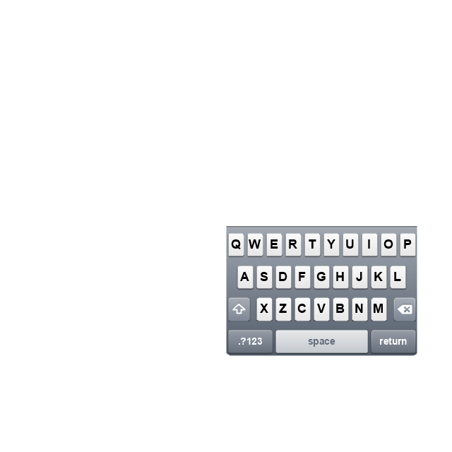
Keyboard control
Keyboard literal button
Keyboard button, pressed
Keyboard label button
Selection frame 1

Selection frame 2
Loupe
Message box 1
Message box 2
Progress view

Progress view

Progress view

Player control
Label button

Back button

Forward button

Option button
Checkbox

Radio button

Alert
Two-button alert
Two-button alert (v 3.0)
-iphone-interface---vector-stencils-library.png--diagram-flowchart-example.png)
Up-Down control

Segmented control
Segmented control

Segmented control
Segmented control
Pop-up menu button

Popup menu

Clock, white
Clock, black

Clock application table

Date and time picker (1/2 parts)
-iphone-interface---vector-stencils-library.png--diagram-flowchart-example.png)
Date and time picker (3 parts)
-iphone-interface---vector-stencils-library.png--diagram-flowchart-example.png)
Date and time picker (4 parts)
-iphone-interface---vector-stencils-library.png--diagram-flowchart-example.png)
Date and time picker (v 3.0)
-iphone-interface---vector-stencils-library.png--diagram-flowchart-example.png)
Switch control
System button
Reply button

Organize button

Remove button

Refresh button

Play button

FastForward button

Pause button

Rewind button

Backward icon
Forward icon
Share button

Camera button

Compose button

Bookmarks button

Search button

Add button

Trash button

Bookmarks tab icon
Contacts tab icon
Downloads tab icon
Favorites tab icon
Featured tab icon
History tab icon
MostRecent tab icon
MostViewed tab icon
Search tab icon
More tab icon
SMS tab icon
Mail tab icon
Charts tab icon
World clock tab icon
Alarm tab icon
Stopwatch tab icon
Timer tab icon
Badge
Delete button control

Checkmark

Delete button

Insert

Disclosure indicator

Clear button

Bookmarks badge
Badge with varying width 1
Badge with varying width 2
Badge with varying width 3
Activity indicator

Network activity indicator

Page control

Search badge
Slider

The vector stencils library "Tables" contains 27 shapes of tables. Use it for drawing room design plans, furniture arrangement and layouts in the ConceptDraw PRO diagramming and vector drawing software extended with the Floor Plans solution from the Building Plans area of ConceptDraw Solution Park.
Square Table 1

Square Table 2
Rectangular Table 1

Rectangular Table 2
Square Table with Rounded Corners 1

Square Table with Rounded Corners 2
Rectangular Table with Rounded Corners 1

Rectangular Table with Rounded Corners 2
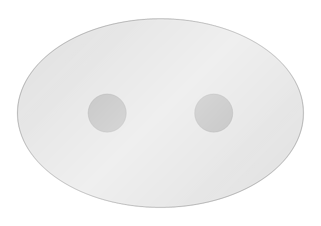
Oval Table 1
Oval Table 2
Round Table 1
Round Table 2
Left Rectangle Table Leaf

Center Table Leaf

Right Rectangle Table Leaf
Rectangular Table 3
Left Oval Table Leaf
Right Oval Table Leaf
Oval Table 3
Corner Table
Boat Shape Table
90 deg Table
45 deg Table
Glass Square Table 1
Glass Square Table 2
Glass Square Table 3
Glass Oval Table
Basic Flowchart Symbols and Meaning


The vector stencils library "Concept maps" contains 16 geometrical shapes.
Use it to create your concept maps, mindmaps, idea maps, tree diagrams, omega maps, cluster diagrams and spider diagrams.
The symbols example "Concept maps - Vector stencils library" was created using the ConceptDraw PRO diagramming and vector drawing software extended with the Concept Maps solution from the area "What is a Diagram" of ConceptDraw Solution Park.
Rectangle

Rounded rectangle

Stadium
Oval
Diamond
Parallelogram

Circle
Star

Hexagon
Cloud
Starburst

Arrow
Envelope

Note
Callout

Table
The vector stencils library "iPhone interface" contains 119 iPhone UI design elements.
Use it for development of graphic user interface (GUI) for iPhone software applications in the ConceptDraw PRO diagramming and vector drawing software extended with the Graphic User Interface solution from the Software Development area of ConceptDraw Solution Park.
Use it for development of graphic user interface (GUI) for iPhone software applications in the ConceptDraw PRO diagramming and vector drawing software extended with the Graphic User Interface solution from the Software Development area of ConceptDraw Solution Park.
iPhone case
iPhone case, horizontal
Display
Screen
Home screen
Keypad control
Status bar
Navigation bar
Navigation bar with buttons
Navigation bar with controls
Navigation bar with controls
Navigation bar with buttons, horizontal
Navigation bar with controls, horizontal
Modal view
Search bar
Text field 1
Text field 2
Text field, varying
Table row
Table view row
Table view (simple list)
Table view (with header)
Action list
Control button
Navigational control button
Add button
Navigation toolbar
Tab bar
Action sheet
Choice button
Rounded rectangle button
Keyboard control
Keyboard literal button
Keyboard button, pressed
Keyboard label button
Selection frame 1
Selection frame 2
Loupe
Message box 1
Message box 2
Progress view
Progress view
Progress view
Player control
Label button
Back button
Forward button
Option button
Checkbox
Radio button
Alert
Two-button alert
Two-button alert (v 3.0)
Up-Down control
Segmented control
Segmented control
Segmented control
Segmented control
Pop-up menu button
Popup menu
Clock, white
Clock, black
Clock application table
Date and time picker (1/2 parts)
Date and time picker (3 parts)
Date and time picker (4 parts)
Date and time picker (v 3.0)
Switch control
System button
Reply button
Organize button
Remove button
Refresh button
Play button
FastForward button
Pause button
Rewind button
Backward icon
Forward icon
Share button
Camera button
Compose button
Bookmarks button
Search button
Add button
Trash button
Bookmarks tab icon
Contacts tab icon
Downloads tab icon
Favorites tab icon
Featured tab icon
History tab icon
MostRecent tab icon
MostViewed tab icon
Search tab icon
More tab icon
SMS tab icon
Mail tab icon
Charts tab icon
World clock tab icon
Alarm tab icon
Stopwatch tab icon
Timer tab icon
Badge
Delete button control
Checkmark
Delete button
Insert
Disclosure indicator
Clear button
Bookmarks badge
Badge with varying width 1
Badge with varying width 2
Badge with varying width 3
Activity indicator
Network activity indicator
Page control
Search badge
Slider
The vector stencils library "UML state machine diagrams" contains 35 symbols for the ConceptDraw PRO diagramming and vector drawing software.
"The state diagram in the Unified Modeling Language is essentially a Harel statechart with standardized notation, which can describe many systems, from computer programs to business processes. In UML 2 the name has been changed to State Machine Diagram. The following are the basic notational elements that can be used to make up a diagram:
(1) Filled circle, pointing to the initial state.
(2) Hollow circle containing a smaller filled circle, indicating the final state (if any).
(3) Rounded rectangle, denoting a state. Top of the rectangle contains a name of the state. Can contain a horizontal line in the middle, below which the activities that are done in that state are indicated.
(4) Arrow, denoting transition. The name of the event (if any) causing this transition labels the arrow body. A guard expression may be added before a "/ " and enclosed in square-brackets ( eventName[guardExpression] ), denoting that this expression must be true for the transition to take place. If an action is performed during this transition, it is added to the label following a "/ " ( eventName[guardExpression]/ action ).
(5) Thick horizontal line with either x>1 lines entering and 1 line leaving or 1 line entering and x>1 lines leaving. These denote join/ fork, respectively." [State diagram (UML). Wikipedia]
The example "Design elements - UML state machine diagrams" is included in the Rapid UML solution from the Software Development area of ConceptDraw Solution Park.
UML state machine diagram symbols

IDEF9 Standard

Data structure diagram with ConceptDraw PRO

The vector stencils library "iPhone interface" contains 119 iPhone UI design elements.
Use it for development of graphic user interface (GUI) for iPhone software applications in the ConceptDraw PRO diagramming and vector drawing software extended with the Graphic User Interface solution from the Software Development area of ConceptDraw Solution Park.
Use it for development of graphic user interface (GUI) for iPhone software applications in the ConceptDraw PRO diagramming and vector drawing software extended with the Graphic User Interface solution from the Software Development area of ConceptDraw Solution Park.
iPhone case
iPhone case, horizontal
Display
Screen
Home screen
Keypad control
Status bar
Navigation bar
Navigation bar with buttons
Navigation bar with controls
Navigation bar with controls
Navigation bar with buttons, horizontal
Navigation bar with controls, horizontal
Modal view
Search bar
Text field 1
Text field 2
Text field, varying
Table row
Table view row
Table view (simple list)
Table view (with header)
Action list
Control button
Navigational control button
Add button
Navigation toolbar
Tab bar
Action sheet
Choice button
Rounded rectangle button
Keyboard control
Keyboard literal button
Keyboard button, pressed
Keyboard label button
Selection frame 1
Selection frame 2
Loupe
Message box 1
Message box 2
Progress view
Progress view
Progress view
Player control
Label button
Back button
Forward button
Option button
Checkbox
Radio button
Alert
Two-button alert
Two-button alert (v 3.0)
Up-Down control
Segmented control
Segmented control
Segmented control
Segmented control
Pop-up menu button
Popup menu
Clock, white
Clock, black
Clock application table
Date and time picker (1/2 parts)
Date and time picker (3 parts)
Date and time picker (4 parts)
Date and time picker (v 3.0)
Switch control
System button
Reply button
Organize button
Remove button
Refresh button
Play button
FastForward button
Pause button
Rewind button
Backward icon
Forward icon
Share button
Camera button
Compose button
Bookmarks button
Search button
Add button
Trash button
Bookmarks tab icon
Contacts tab icon
Downloads tab icon
Favorites tab icon
Featured tab icon
History tab icon
MostRecent tab icon
MostViewed tab icon
Search tab icon
More tab icon
SMS tab icon
Mail tab icon
Charts tab icon
World clock tab icon
Alarm tab icon
Stopwatch tab icon
Timer tab icon
Badge
Delete button control
Checkmark
Delete button
Insert
Disclosure indicator
Clear button
Bookmarks badge
Badge with varying width 1
Badge with varying width 2
Badge with varying width 3
Activity indicator
Network activity indicator
Page control
Search badge
Slider
Cross Functional Flowchart Symbols

The vector stencils library "Concept maps" contains 16 geometrical shapes.
Use it to create your concept maps, mindmaps, idea maps, tree diagrams, omega maps, cluster diagrams and spider diagrams.
The symbols example "Concept maps - Vector stencils library" was created using the ConceptDraw PRO diagramming and vector drawing software extended with the Concept Maps solution from the area "What is a Diagram" of ConceptDraw Solution Park.
Use it to create your concept maps, mindmaps, idea maps, tree diagrams, omega maps, cluster diagrams and spider diagrams.
The symbols example "Concept maps - Vector stencils library" was created using the ConceptDraw PRO diagramming and vector drawing software extended with the Concept Maps solution from the area "What is a Diagram" of ConceptDraw Solution Park.
Rectangle
Rounded rectangle
Stadium
Oval
Diamond
Parallelogram
Circle
Star
Hexagon
Cloud
Starburst
Arrow
Envelope
Note
Callout
Table
Cross Functional Flowchart

This vector stencils library contains 47 SysML activity diagram symbols.
Use it to design your SysML activity diagrams using ConceptDraw PRO diagramming and vector drawing software.
"Activity diagrams are constructed from a limited number of shapes, connected with arrows. The most important shape types:
- rounded rectangles represent actions;
- diamonds represent decisions;
- bars represent the start (split) or end (join) of concurrent activities;
- a black circle represents the start (initial state) of the workflow;
- an encircled black circle represents the end (final state).
Arrows run from the start towards the end and represent the order in which activities happen." [Activity diagram. Wikipedia]
The vector stencils library "Activity diagram" is included in the SysML solution from the Software Development area of ConceptDraw Solution Park.
Action

Call behavior action

Accept event action

Accept time event action

Send signal action

Activity

Activity final node

Flow final node

Activity parameter node

Control operator node

Control operator - frame

Decision/Merge node

Fork/Join node

Initial node

isControl

isStream

isStream 2

isStream 3

Local precondition

Local postcondition

NoBuffer

Object node

Object node 2

Optional

Optional 2

OverWrite

Parameter set

Parameter set 2

Probability

Probability 2

Rate

Rate 2

Rate 3

Rate 4

Rate 5

Rate 6

Control flow

Control flow 2

Object flow

Object flow 2

Probability path

Rate path

In block definition diagram, activity, association

Activity partition

Activity partition - action

Interruptible activity region

Structured activity node

UML State Machine Diagram.Design Elements

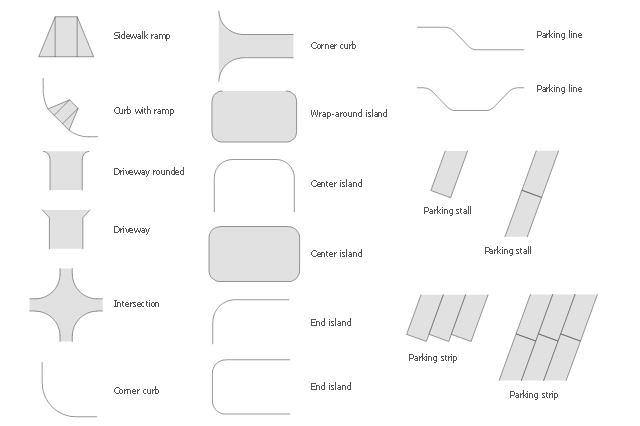
The vector stencils library Parking and roads contains 18 symbols of parking lots and strips, parking spaces, driveways, street junctions, and interchanges for parking facilities, on-street and off-street parking, and traffic management.
"A parking space is a location that is designated for parking, either paved or unpaved.
Parking spaces can be in a parking garage, in a parking lot or on a city street. It is usually designated by a white-paint-on-tar rectangle indicated by three lines at the top, left and right of the designated area. The automobile fits inside the space, either by parallel parking, perpendicular parking or angled parking." [Parking space. Wikipedia]
Use the design elements library Parking and roads to draw residential and commercial landscape design, parks planning, yard layouts, plat maps, outdoor recreational facilities, and irrigation systems using the ConceptDraw PRO diagramming and vector drawing software.
The shapes library Parking and roads is contained in the Site Plans solution from the Building Plans area of ConceptDraw Solution Park.
Flowchart

- Computer network - Vector stencils library
- iPhone interface - Vector stencils library
- Round Table
- Rounded Arrow Vector
- Basic Flowchart Symbols and Meaning | TQM diagrams - Vector ...
- Rounded Corners
- Symbol for Pool Table for Floor Plans | Seating Plans | Table ...
- Oval Table
- Tables - Vector stencils library
- Rectangular Table
- iPhone interface - Vector stencils library | iPhone OS (iOS) graphic ...
- iPhone interface - Vector stencils library | iPhone interface - Vector ...
- Concept maps - Vector stencils library | Concept Maps | How To ...
- iPhone interface - Vector stencils library | iPhone interface - Vector ...
- iPhone OS (iOS) graphic user interface (GUI) - Clock application ...
- Diagramming Software for Design UML Activity Diagrams | UML ...
- iPhone interface - Vector stencils library | Design elements - Alarm ...
- iPhone interface - Vector stencils library | How to Create Multiple ...
- Tables - Vector stencils library
- UML State Machine Diagram.Design Elements | UML Diagram ...