Mechanical Drawing Symbols
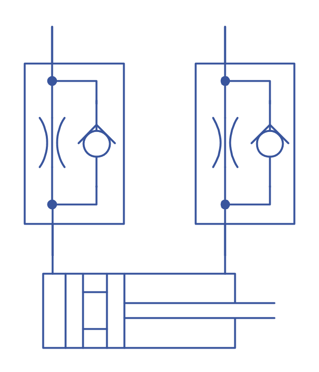
Working as a mechanic being responsible for making the appropriate drawings, including technical ones, working with ventilating, heating or air conditioning, you may find it exhausting creating all of schemes by hand using the ruler, for example. In this case we can recommend to download ConceptDraw DIAGRAM which is professional software that can make your life simpler and help you to achieve your goals at work in your business. 8 libraries are available with 602 commonly used mechanical drawing symbols in Mechanical Engineering Solution, including libraries called Bearings with 59 elements of roller and ball bearings, shafts, gears, hooks, springs, spindles and keys; Dimensioning and Tolerancing with 45 elements; Fluid Power Equipment containing 113 elements of motors, pumps, air compressors, meters, cylinders, actuators and gauges; Fluid Power Valves containing 93 elements of pneumatic and hydraulic valves (directional control valves, flow control valves, pressure control valves) and electrohydraulic and electropneumatic valves; as well as many other sophisticated symbols and templates for your use.
 Mechanical Engineering Solution. ConceptDraw.com
mechanical drawing software (or later) with samples of mechanical drawing
for help when drafting mechanical engineering drawings , or parts, assembly ,
This technical drawing shows the machine parts assembly using joining by
threaded Wikipedia] This mechanical engineering drawing example was
designed
Technical Drawing Software
Being a technologist, engineer, designer, architect or technician can put lots of pressure on you, especially when you have to create lots of drawings within your work hours, such as technical schemes and plans. Making diagrams you need proper professional software with available samples to be able to use them as the drafts in terms of creating your own schemes. In case you have enough symbols and design elements, as well as templates and examples for drawing everything you need in respect of completing your work on time, you might like using the very special software ConceptDraw DIAGRAM with extension as it is one of the best and sophisticated tools for engineers and technicians. There are 8 libraries of 602 design elements in Mechanical Engineering Solution, 26 libraries of 926 design elements in Electrical Engineering Solution and 8 libraries of 468 design elements in Chemical and Process Engineering Solution which should be more than enough for technical drawing.HelpDesk
Creating a Create a Mechanical Diagram. ConceptDraw HelpDesk
You can design elements for drawing parts, assembly , pneumatic, and hydraulic systems for mechanical engineering. With ConceptDraw DIAGRAM you canCAD Drawing Software for Making Mechanic Diagram and Electrical
Working as a designer creating the diagrams you definitely need an application to help you with your ordinary tasks. The CAD drawing software for making mechanical and electrical diagrams as well as architectural designs is called ConceptDraw DIAGRAM one and it can be useful for making special designs with help of so many layouts and examples available now in the Solution Park on this site. You’ll find it simple to make the computer-aided design in order to please your clients in many different spheres of businesses and mechanical and industrial design are not a comprehensive list of them. Feel as if you were a professional designer even if you have almost no experience in it using the samples we offer to change the basic information so your final scheme satisfies your requirements. As a result you will get the vector graphic documents which can be reviewed, modified and converted to so many different formats such as: MS Visio, HTML, image, PDF file, Adobe Flash or MS PowerPoint Presentation.Wikipedia] The shapes example "" was created using the ConceptDraw PRO
diagramming and vector drawing software extended with the Mechanical
Use it for drawing the wiring diagrams, electrical layouts, electronic schematics,
and device for joining electrical circuits as an interface using a mechanical
assembly . Wikipedia] The shapes example "Design elements - Terminals and
Electrical Symbols, Electrical Diagram Symbols
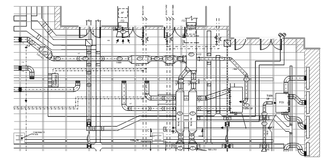
Once you have to draw some electrical diagram, then you can use ConceptDraw DIAGRAM for making it within a couple of minutes having numerous libraries of stencil elements, such as VHF, UHF, SHF, Transmission Paths, Transistors, Transformers and Windings, Thermo, Terminals and Connectors with 43 design elements, Switches and Relays with 58 symbols, Stations with 110 symbols, Semiconductors with 22 elements, Semiconductor Diodes with 24, Rotating Equipment with 55, Resistors with 14 design elements, Qualifying with 56, Power Sources with 9 symbols as well as Maintenance one which were previously made by the specialists with help of our designers so our clients have all kinds of needed stencils to create any kind of diagram, plan, chart or flowchart, or scheme. Downloading our application is the first step to make sure the final diagram will look very smart and professional.This mechanical systems drawing sample was designed on the base of
Wikimedia Commons file: Building services coordinated drawing .JPG.
Electrical Symbols. Terminals and Connectors
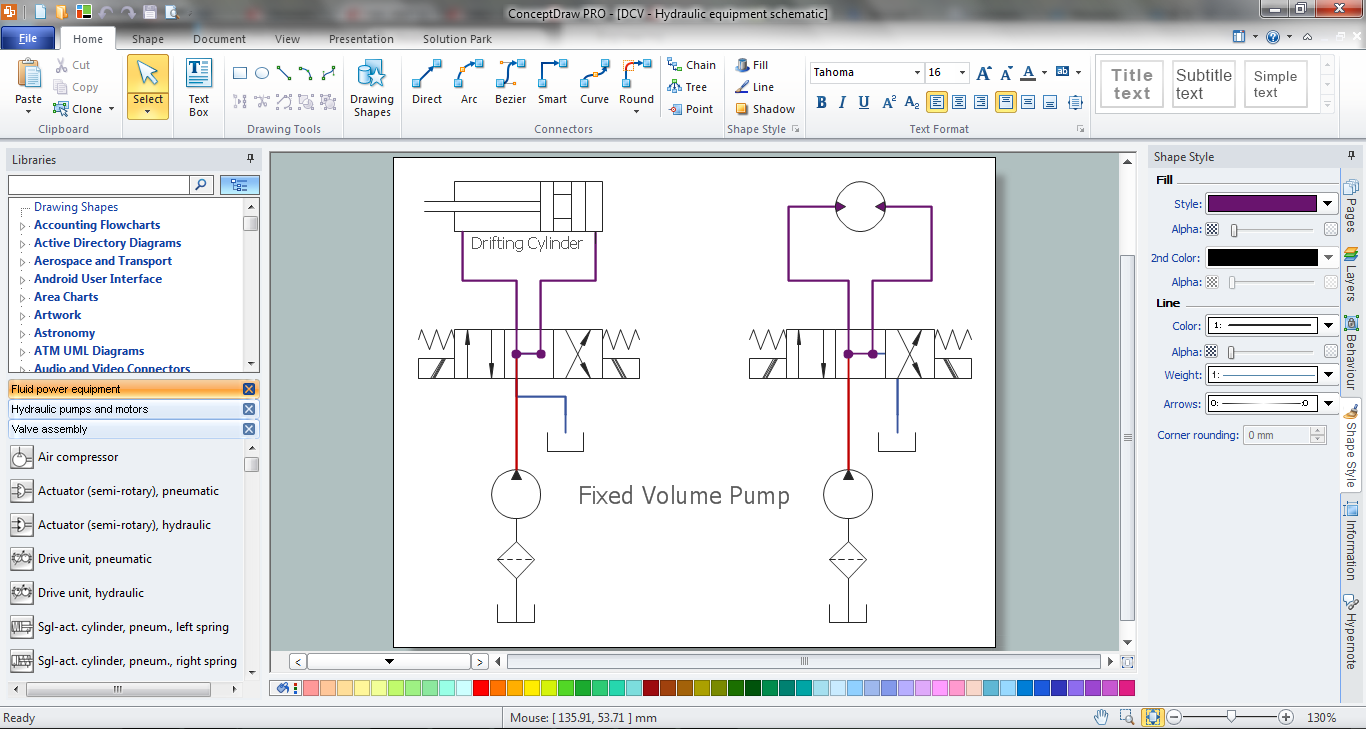
Electrical Symbols — Terminals and ConnectorsWikipedia] The fluid power equipment drawing example "Directional control valve
" is included in the Mechanical Engineering solution from the Engineering area
Wikipedia] This hydraulic schematic example was redrawn using and vector
drawing software extended with the Mechanical Engineering solution from the
Components of ER Diagram. Professional ERD Drawing
In order to model some data, illustrate the logical structure and system design of databases, the Entity Relationship Diagram (ERD or ER Diagram as well as E-R Diagram) was introduced by Peter Chen as a modeling technique for software development. Using three main elements which are attributes, entities and relationships make possible to create so called ERD and to do it with help of ConceptDraw DIAGRAM software is simpler than ever now. As once you download ConceptDraw STORE, you will find the samples of ERDs which you can use for making your own diagram in short terms using all the elements necessary for this purpose. Immensely popular in software engineering this method for modeling database is common for IT engineers use as well as any other IT specialists once they want to succeed in their job. So why not to try our application just now to make sure you keep up with the times and use all necessary tools for achieving your goals?Digital Communications Network. Computer and Network Examples
Digital communications network
 Fire and Emergency Plans Solution. ConceptDraw.com
Mechanical Engineering Free · Specification and Description Language .
This sample diagram illustrates the fire emergency plan for an apartment. start
in drawing the fire protection and emergency plans, or simply as an example for
. are showed emergency exits, assembly points, and location of fire
extinguishers.
- Mechanical Drawing Symbols | Mechanical Engineering | How to ...
- Mechanical Drawing Symbols | Mechanical Engineering ...
- Sample Assembly Drawing
- Mechanical Engineering | Assembly Drawing Examples And ...
- Mechanical Engineering | Mechanical Assembly Drawing Symbols Pdf
- Mechanical Drawing Symbols | Engineering | Technical Drawing ...
- Examples For Simple Mechanical Assembly
- Documents On Engineering Assembly Drawing Pdf
- Mechanical Drawing Example
- Mechanical Assembly Drawing Solution
- Mechanical Engineering | Technical drawing - Machine parts ...
- Solutions Of Assembly Drawings
- Mechanical Drawing Symbols | Process Flowchart | Flow chart ...
- Design elements - Valve assembly | Detail And Assembly Drawing ...
- Mechanical Assembly Drawing Of A One Way Valve
- Mechanical Drawing Symbols | Mechanical Engineering | Technical ...
- Mechanical Drawing Symbols | Technical drawing - Machine parts ...
- Mechanical Drawing Symbols | Mechanical Engineering | Design ...
- Mechanical Drawing Symbols | Mechanical Engineering ...
- Assembly Drawing Exercises And Solutions Pdf Download


