Technical Drawing Software
Being a technologist, engineer, designer, architect or technician can put lots of pressure on you, especially when you have to create lots of drawings within your work hours, such as technical schemes and plans. Making diagrams you need proper professional software with available samples to be able to use them as the drafts in terms of creating your own schemes. In case you have enough symbols and design elements, as well as templates and examples for drawing everything you need in respect of completing your work on time, you might like using the very special software ConceptDraw DIAGRAM with extension as it is one of the best and sophisticated tools for engineers and technicians. There are 8 libraries of 602 design elements in Mechanical Engineering Solution, 26 libraries of 926 design elements in Electrical Engineering Solution and 8 libraries of 468 design elements in Chemical and Process Engineering Solution which should be more than enough for technical drawing.Mechanical Drawing Symbols
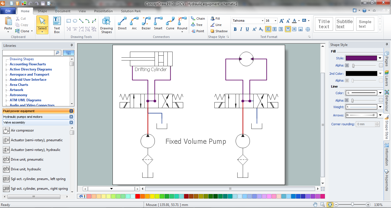
Working as a mechanic being responsible for making the appropriate drawings, including technical ones, working with ventilating, heating or air conditioning, you may find it exhausting creating all of schemes by hand using the ruler, for example. In this case we can recommend to download ConceptDraw DIAGRAM which is professional software that can make your life simpler and help you to achieve your goals at work in your business. 8 libraries are available with 602 commonly used mechanical drawing symbols in Mechanical Engineering Solution, including libraries called Bearings with 59 elements of roller and ball bearings, shafts, gears, hooks, springs, spindles and keys; Dimensioning and Tolerancing with 45 elements; Fluid Power Equipment containing 113 elements of motors, pumps, air compressors, meters, cylinders, actuators and gauges; Fluid Power Valves containing 93 elements of pneumatic and hydraulic valves (directional control valves, flow control valves, pressure control valves) and electrohydraulic and electropneumatic valves; as well as many other sophisticated symbols and templates for your use.Wikipedia] This mechanical engineering drawing example was designed using
ConceptDraw PRO diagramming and vector drawing software extended with
 Mechanical Engineering Solution. ConceptDraw.com
This solution extends ConceptDraw DIAGRAM.9 mechanical drawing for help
when drafting mechanical engineering drawings , or parts , assembly, pneumatic,
HelpDesk
Creating a Create a Mechanical Diagram. ConceptDraw HelpDesk
You can design elements for drawing parts , assembly, pneumatic, and hydraulic systems for mechanical engineering . With ConceptDraw DIAGRAM you canUse it to design engineering drawings of machine tools and mechanical devices.
motion and reduce friction between moving parts to only the desired motion.
Technical Drawing Software
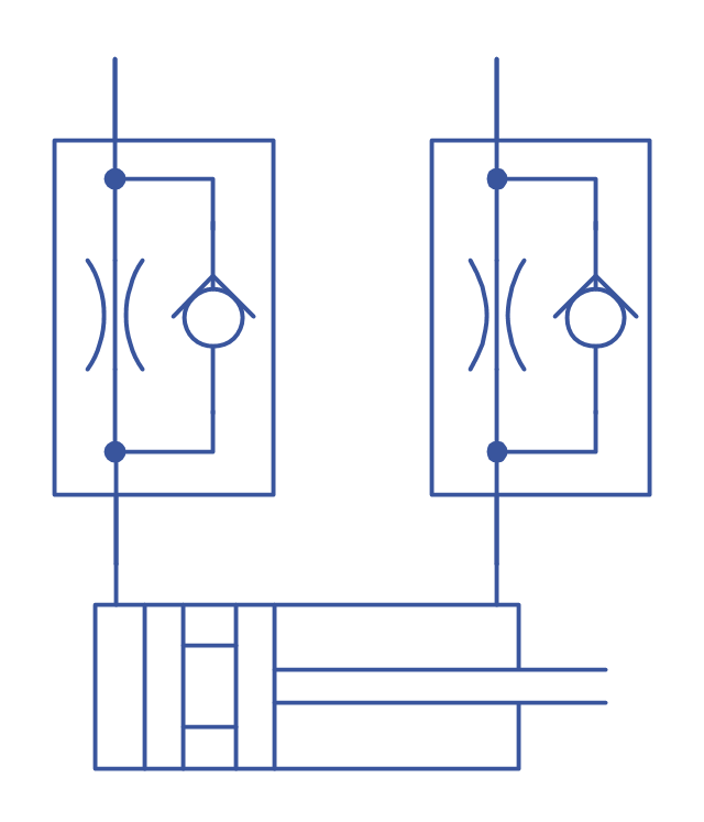
Working as an electrician, mechanic, engineer, architect or plumber, you may need to make your own engineering drawings in terms of understanding if all the elements of them are in order and on its places. Using ConceptDraw DIAGRAM software is a way of succeeding in creating Electrical Schematics, Drawings: Mechanical Systems, Technical, Architectural, Structural, Plumbing as well as Facility Plans and different diagrams: Block and Circuit, for example. Having our Mechanical Engineering Solution means having 8 libraries with 602 pre-designed elements, such as Bearings, Hydraulic and Pneumatic Pumps and Motors, Welding, Dimensioning and Tolerancing, Fluid Power - Equipment and Fluid Power - Valves as well as Valve Assembly. If you have this technical drawing tool, then we can ensure you that once you use our templates as well as the vector objects, it will guarantee your success in creating diagrams and other technical drawings. Download ConceptDraw DIAGRAM today to ensure yourself in the fact this is the best product for assisting and simplifying your work and so your life.Use these valve assembly shapes to design the engineering drawings of
hydraulic and A control valve consists of three main parts in which each part
exist in and vector drawing software extended with the Mechanical
Engineering solution
Design Element: Plumbing. Professional Building Drawing
Making building drawing having more than 20 examples of already pre-designed plans as well as 16 templates for creating any kind of engineering drawing sounds like a very simple thing, isn’t it? With help of our ConceptDraw DIAGRAM software it is truly simple as there are 1493 vector stencils from the 49 libraries available for your use in terms of making any kind of building drawing using any of these design elements for making plumbing plans and so on. Plumbing library consists of 21 design objects and there are 3 vector stencils libraries more with 107 design elements, such as pipes, valves and other sanitary equipment for making plumbing and piping plans so they look professional. Also they can be useful for creating annotated diagrams as well as schematics of waste water disposal systems, hot and cold water supply systems, water lines, plumbing systems and waste water engineering. Even if you never had any experience of making any similar plans, we can ensure you that using ConceptDraw DIAGRAM is possible to have a great looking result as if you were engineer in case you do not know much about engineering at all.Wiring Diagram with ConceptDraw DIAGRAM
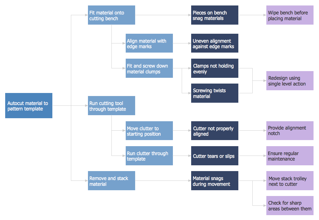
Illustrating electrical circuit system representing the wiring, connectors, all terminal boards, signal connections (or buses) between the devices as well as electrical or electronic components of this circuit, is better in a way of simple wiring diagram. To draw such diagram which helps to identify the wires by color coding or wire numbers is simple with help of ConceptDraw DIAGRAM which can be used together with vector symbols and special elements from numerous libraries as well as using our templates designed in advance in order to provide you with so many different choices of examples. Find our 26 libraries with 926 electrical symbols to make your own sophisticated great looking wiring diagrams and to make it possible to use software for other purposes in case you get used to it and it will happen very soon as our product is simple to use. Try today to be much better at utilizing it tomorrow in order to succeed and to make your business prospering.Preventive Action. 7 Management and Planning Tools. Problem
Preventive Action. Process decision program chart (PDPC) - Minimization-of-material-wastageCheck valves are often part of common household items. vector drawing
software extended with the Mechanical Engineering solution from the
Engineering
"Directional control valves are one of the most fundamental parts in hydraulic
Wikipedia] This example engineering drawing showing the directional control
the Mechanical Engineering solution from the Engineering area of ConceptDraw
This example engineering drawing showing the hydraulic directional control
valve fundamental parts in hydraulic machinery as well and pneumatic
machinery. "Directional control valve" is included in the Mechanical
Engineering solution
GD&T is used to define the nominal (theoretically perfect) geometry of parts and
vector drawing software extended with the Mechanical Engineering solution
Drawing Program. Download ConceptDraw and draw anything easily!
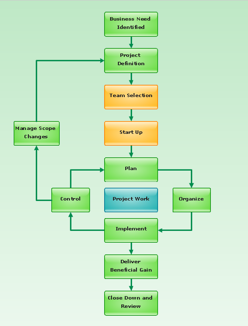
Flowchart - Project Management Life Cycle- Mechanical Engineering | Technical drawing - Machine parts ...
- Technical drawing - Machine parts assembling | Mechanical ...
- Mechanical Engineering Drawing Parts
- Mechanical Drawing Symbols | Design elements - Bearings ...
- Mechanical Drawing Symbols | Mechanical Engineering ...
- Mechanical Engineering | Technical drawing - Machine parts ...
- Bearing In Engineering Drawing Part S
- Mechanical Engineering | Technical drawing - Machine parts ...
- Design elements - Bearings | Mechanical Engineering | Bearings ...
- Mechanical Drawing Symbols | Mechanical Engineering ...
- Process Flow Diagram Symbols | How to Create a Mechanical ...
- Mechanical All Parts Drawing Symbol With Meaning Use
- Technical drawing - Machine parts assembling | How to Create a ...
- Mechanical Parts Drawings
- Technical Drawing Software | How to Create a Mechanical Diagram ...
- Technical Drawings Mechanical Components
- Mechanical Drawing Symbols | Interior Design. Machines and ...
- Design elements - Bearings | Engineering | Machine Design ...
- Mechanical Drawing Symbols | Mechanical Engineering | How to ...
- Mechanical Drawing Symbols | Technical drawing - Machine parts ...


