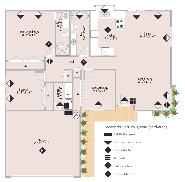
This sample was created on the base of the floor plan with security system device symbols from the website of the California State University, Sacramento. [imet.csus.edu/ imet1/ denyer/ mhs_ denyer/ drafting/ arch_ ch_ 31/ 31-28.jpg]
Legend for the security system hardware includes distribution panel, window-door contact, sonic detector, key pads, heat detectors, smoke detectors.
The example "Security system floor plan" was created using the ConceptDraw PRO diagramming and vector drawing software extended with the Security and Access Plans solution from the Building Plans area of ConceptDraw Solution Park.
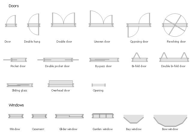
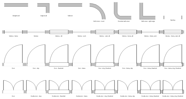
The design elements library Doors contains 69 symbols of doors.
The design elements library Windows contains 34 symbols of windows and casements.
"A door is an opening or closing structure used to block off an entrance, typically consisting of an interior side that faces the inside of a space and an exterior side that faces the outside of that space. While in some cases the interior side of a door may match its exterior side, in other cases there are sharp contrasts between the two sides, such as in the case of the vehicle door. In addition, doors typically consist of a panel that swings on hinges or that slides or spins inside of a space." [Door. Wikipedia]
"A window is an opening in a wall, door or vehicle that allows the passage of light and, if not closed or sealed, air and sound. Modern windows are usually glazed or covered in some other transparent or translucent material. Windows are held in place by frames. Many glazed windows may be opened, to allow ventilation, or closed, to exclude inclement weather." [Window. Wikipedia]
Use the shapes libraries Doors and Windows to create house plans, home plans, floor plan layouts and home designs using the ConceptDraw PRO diagramming and vector drawing software.
The vector stencils libraries Doors and Windows are provided by the Floor Plans solution from the Building Plans area of ConceptDraw Solution Park.
This cafe electrical floor plan sample shows the outlet and switch layout.
"An electrical drawing, is a type of technical drawing that shows information about power, lighting, and communication for an engineering or architectural project. Any electrical working drawing consists of "lines, symbols, dimensions, and notations to accurately convey an engineering's design to the workers, who install the electrical system on the job".
A complete set of working drawings for the average electrical system in large projects usually consists of:
(1) A plot plan showing the building's location and outside electrical wiring.
(2) Floor plans showing the location of electrical systems on every floor.
(3) Power-riser diagrams showing panel boards.
(4) Control wiring diagrams.
(5) Schedules and other information in combination with construction drawings.
Electrical drafters prepare wiring and layout diagrams used by workers who erect, install, and repair electrical equipment and wiring in communication centers, power plants, electrical distribution systems, and buildings." [Electrical drawing. Wikipedia]
The outlet and switch layout example "Cafe electrical floor plan" was created using the ConceptDraw PRO diagramming and vector drawing software extended with the Electric and Telecom Plans solution from the Building Plans area of ConceptDraw Solution Park.
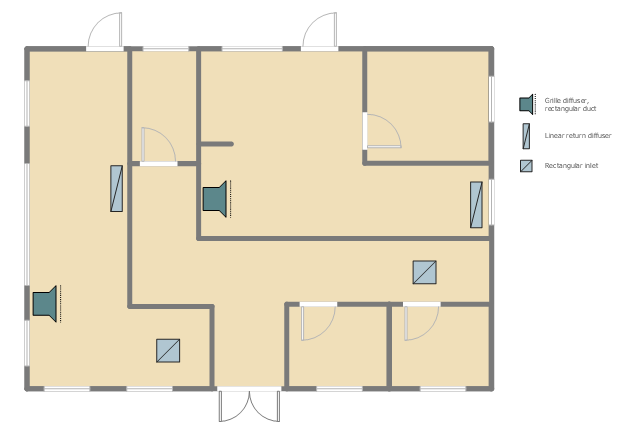
This reflected ceiling plan sample was created on the base of the article "How to Read a Reflected Ceiling Plan" from wikiHow.com.
"A reflected ceiling plan (RCP) is a drawing, which shows the items that are located on the ceiling of a room or space. It is referred to as a reflected ceiling plan since it is drawn to display a view of the ceiling as if it was reflected onto a mirror on the floor. This way the reflected ceiling plan has the same orientation as the floor plan associated with it. It is as if the ceiling was see-through and you could see right through it to the floor below. Architects and interior designers draw reflected ceiling plans when designing spaces." [wikihow.com/ Read-a-Reflected-Ceiling-Plan]
The HVAC layout example "RCP- HVAC layout" was created using the ConceptDraw DIAGRAM diagramming and vector drawing software extended with the Reflected Ceiling Plans solution from the Building Plans area of ConceptDraw Solution Park.
How To Make a Floor Plan
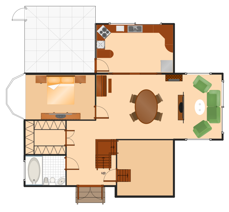
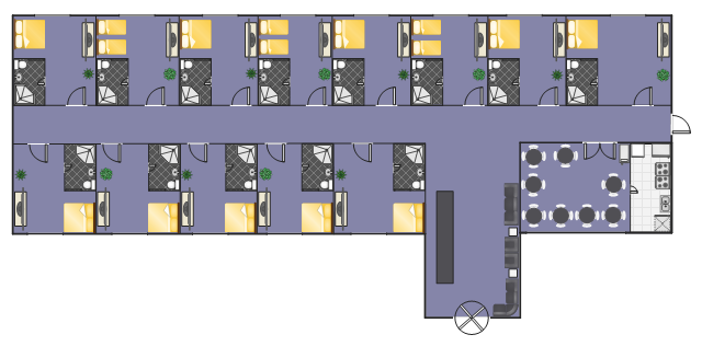
How To Make a Floor Plan? Usually drawing of Floor Plans is quite complex and time-taking process. But now thanks to the ConceptDraw DIAGRAM diagramming and vector drawing software extended with Floor Plans Solution from the Building Plans area of ConceptDraw Solution Park this process became quick and simple.This example depicts furniture and home appliances layout on the hotel floor plan.
"A hotel is an establishment that provides lodging paid on a short-term basis. The provision of basic accommodation, in times past, consisting only of a room with a bed, a cupboard, a small table and a washstand has largely been replaced by rooms with modern facilities, including en-suite bathrooms and air conditioning or climate control. Additional common features found in hotel rooms are a telephone, an alarm clock, a television, a safe, a mini-bar with snack foods and drinks, and facilities for making tea and coffee. Luxury features include bathrobes and slippers, a pillow menu, twin-sink vanities, and jacuzzi bathtubs. Larger hotels may provide additional guest facilities such as a swimming pool, fitness center, business center, childcare, conference facilities and social function services." [Hotel. Wikipedia]
The example "Hotel floor plan" was created using the ConceptDraw PRO diagramming and vector drawing software extended with the Floor Plans solution from the Building Plans area of ConceptDraw Solution Park.
This cafe electrical floor plan sample shows the outlet and switch layout.
"An electrical drawing, is a type of technical drawing that shows information about power, lighting, and communication for an engineering or architectural project. Any electrical working drawing consists of "lines, symbols, dimensions, and notations to accurately convey an engineering's design to the workers, who install the electrical system on the job".
A complete set of working drawings for the average electrical system in large projects usually consists of:
(1) A plot plan showing the building's location and outside electrical wiring.
(2) Floor plans showing the location of electrical systems on every floor.
(3) Power-riser diagrams showing panel boards.
(4) Control wiring diagrams.
(5) Schedules and other information in combination with construction drawings.
Electrical drafters prepare wiring and layout diagrams used by workers who erect, install, and repair electrical equipment and wiring in communication centers, power plants, electrical distribution systems, and buildings." [Electrical drawing. Wikipedia]
The outlet and switch layout example "Cafe electrical floor plan" was created using the ConceptDraw PRO diagramming and vector drawing software extended with the Electric and Telecom Plans solution from the Building Plans area of ConceptDraw Solution Park.
"An electrical drawing, is a type of technical drawing that shows information about power, lighting, and communication for an engineering or architectural project. Any electrical working drawing consists of "lines, symbols, dimensions, and notations to accurately convey an engineering's design to the workers, who install the electrical system on the job".
A complete set of working drawings for the average electrical system in large projects usually consists of:
(1) A plot plan showing the building's location and outside electrical wiring.
(2) Floor plans showing the location of electrical systems on every floor.
(3) Power-riser diagrams showing panel boards.
(4) Control wiring diagrams.
(5) Schedules and other information in combination with construction drawings.
Electrical drafters prepare wiring and layout diagrams used by workers who erect, install, and repair electrical equipment and wiring in communication centers, power plants, electrical distribution systems, and buildings." [Electrical drawing. Wikipedia]
The outlet and switch layout example "Cafe electrical floor plan" was created using the ConceptDraw PRO diagramming and vector drawing software extended with the Electric and Telecom Plans solution from the Building Plans area of ConceptDraw Solution Park.
The vector stencils library "Home plan" contains 31 floor plan shapes.
Use it to design your landscape design, garden plans, house plans, home improvement blueprints, home construction and remodeling projects.
The shapes example "Design elements - Home plan" was created using the ConceptDraw PRO diagramming and vector drawing software extended with the Landscape & Garden solution from the Building Plans area of ConceptDraw Solution Park.
- Security system floor plan | Awning Window Symbol
- Symbol For Awning Window On Floor Plan
- Awning Window Plan
- Glass Wall Floor Plan Symbol
- Design elements - Doors and windows | Network Layout Floor Plans ...
- Windows - Vector stencils library | Mini Hotel Floor Plan . Floor Plan ...
- How To Draw Bay Windows On A Floor Plan
- Windows Symbol In Floor Plan
- Image Of Casement Window With Glass Pane On Floor Plan
