HelpDesk
How to Add and Edit Connector Text

UML Component Diagram. Design Elements


HelpDesk
How to Connect Objects on PC

UML Deployment Diagram. Design Elements

How To Create Professional Diagrams
UML Composite Structure Diagram. Design Elements

HelpDesk
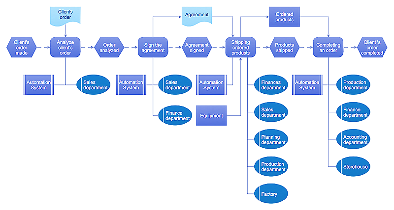
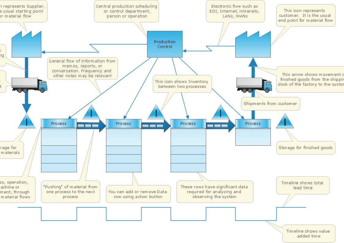
Event-driven Process Chain (EPC) Diagram Software
ConceptDraw Arrows10 Technology

ConceptDraw Arrows10 Technology

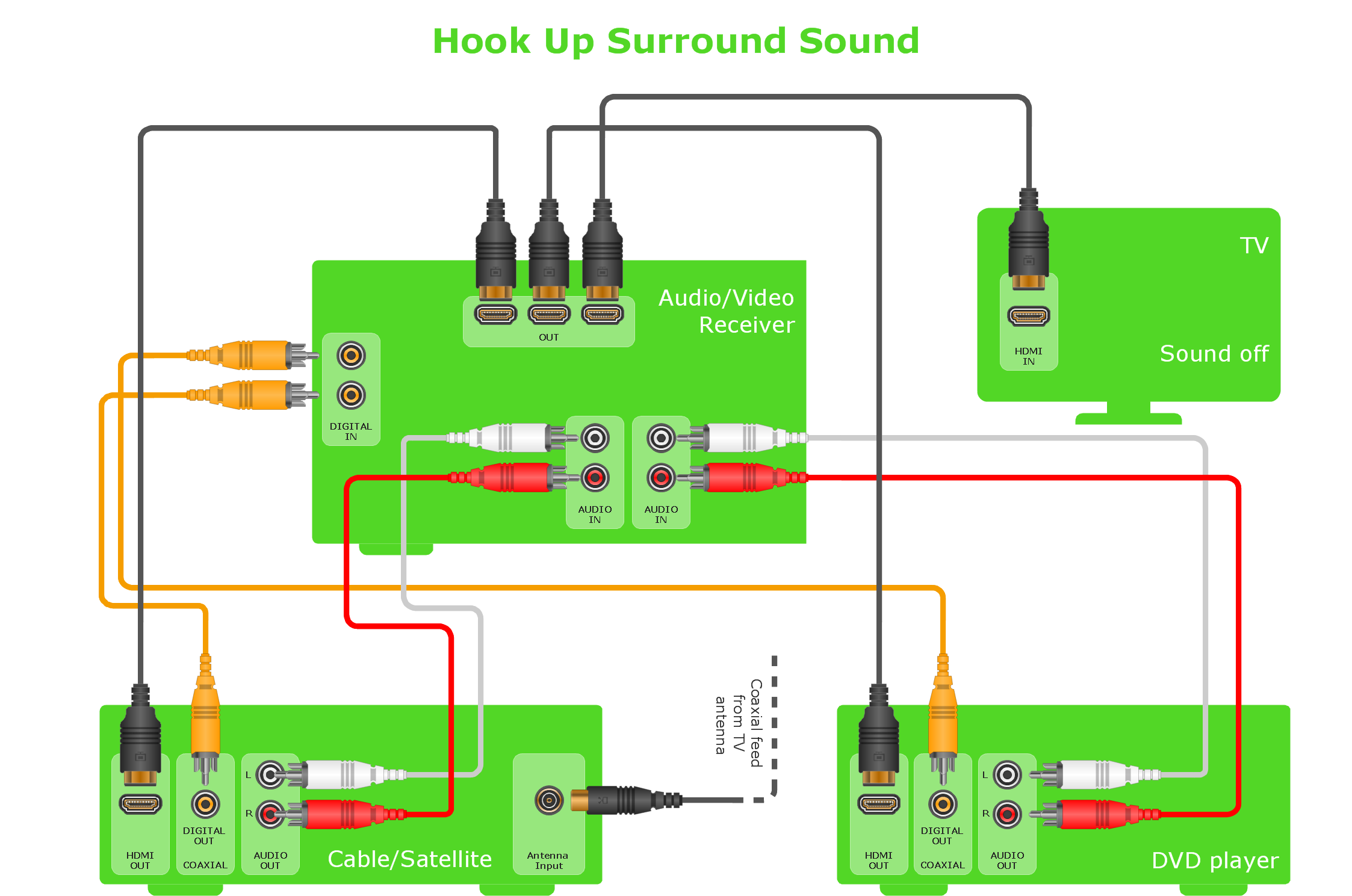
 Audio and Video Connectors
The Audio and Video Connectors solution contains a set of video connectors, audio connectors and s video connection; you will also find pre-designed objects, libraries, templates, and samples, allowing quick and easy diagramming of various configurations
ConceptDraw Arrows10 Technology
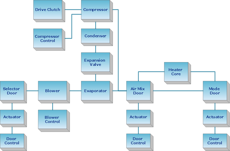
Create Block Diagram
ConceptDraw DIAGRAM Network Diagram Tool


Audio & Video Connector Types
UML Use Case Diagram. Design Elements

ConceptDraw Arrows10 Technology
ConceptDraw Arrows10 Technology
HelpDesk
How to Create an Electrical Diagram

UML Class Diagram. Design Elements

HelpDesk
How to Create Cisco Network Diagram

- DVI pinout diagram | DVI connector types | Connector Pinout Diagram
- ERD Symbols and Meanings | Entity Relationship Diagram Symbols ...
- How to Create a Hook Up Diagram | Audio and Video Connectors ...
- Create Professional Looking Diagrams | ConceptDraw Arrows10 ...
- How to Set Line Jumps for Smart Connectors in ConceptDraw PRO ...
- Audio and Video Connectors | Fishbone Diagram | Audio Visual ...
- VGA connector pinout | ConceptDraw Arrows10 Technology | DVI ...
- Audio and Video Connectors | How To Create CCTV Network ...
- Diagram Of A Connector
- Design elements - Bank UML composite structure diagram | Basic ...
- Audio and Video Connectors | Audio Visual Connectors Types ...
- Audio & Video Connector Types | Audio and Video Interfaces and ...
- Audio and Video Connectors | How to Make a Hook Up Diagram ...
- Audio and Video Connectors
- Audio Connectors | ConceptDraw Arrows10 Technology | Video ...
- Audio & Video Connector Types | Standard Universal Audio & Video ...
- Audio and Video Connectors | How to Make a Hook Up Diagram ...
- Audio and Video Connectors | CCTV Network Diagram Software ...
- Audio and Video Connectors
- Terminals and connectors - Vector stencils library | Audio and video ...