The vector stencils library "Electrical and telecom" contains 83 symbols of electrical and telecommunication equipment for electrical drawings and wiring diagrams of buildings, communication centers, power plants and electrical distribution systems.
"An electrical drawing, is a type of technical drawing that shows information about power, lighting, and communication for an engineering or architectural project." [Electrical drawing. Wikipedia]
Use the design elements library "Electrical and telecom" to design your own electrical drawings, plot plans of the building outside electrical wiring, floor plans with electrical and telecommunication systems layout, power-riser diagrams with panel boards, control wiring diagrams and cabling layout schemes, reflected ceiling plans and lighting panels layouts using the ConceptDraw PRO diagramming and vector drawing software.
The shapes library "Electrical and telecom" is included in the Electric and Telecom Plans solution from the Building Plans area of ConceptDraw Solution Park.
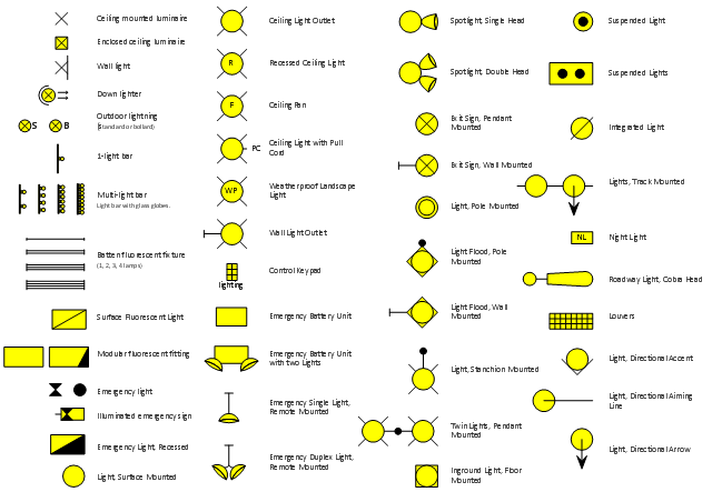
The vector stencils library "Lighting" contains 55 symbols of lighting devices and equipment, light sources, lamps and light fixtures.
"Lighting or illumination is the deliberate use of light to achieve a practical or aesthetic effect. Lighting includes the use of both artificial light sources like lamps and light fixtures, as well as natural illumination by capturing daylight.
Indoor lighting is usually accomplished using light fixtures, and is a key part of interior design. Lighting can also be an intrinsic component of landscape projects." [Lighting. Wikipedia]
Use the design elements library "Lighting" for drawing lighting design floor plans, circuit schematic and wiring diagrams, cabling layouts, and reflected ceiling plans using the ConceptDraw PRO diagramming and vector drawing software.
The shapes library "Lighting" is included in the Electric and Telecom Plans solution from the Building Plans area of ConceptDraw Solution Park.
The vector stencils library "Lighting" contains 55 symbols of lighting devices and equipment.
Use these shapes for drawing lighting design floor plans, circuit schematic and wiring diagrams, cabling layouts, and reflected ceiling plans in the ConceptDraw PRO diagramming and vector drawing software.
The vector stencils library "Lighting" is included in the Electric and Telecom Plans solution from the Building Plans area of ConceptDraw Solution Park.
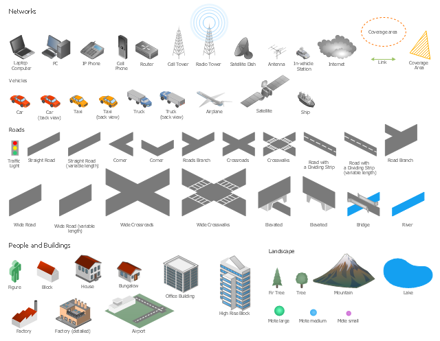
The vector stencils library "Local vehicular networking" contains 88 symbols for drawing the vehicular computer telecommunication network diagrams using the ConceptDraw PRO diagramming and vector drawing software.
"A vehicular ad hoc network (VANET) uses cars as mobile nodes in a MANET to create a mobile network.[1] A VANET turns every participating car into a wireless router or node, allowing cars approximately 100 to 300 metres of each other to connect and, in turn, create a network with a wide range. As cars fall out of the signal range and drop out of the network, other cars can join in, connecting vehicles to one another so that a mobile Internet is created. It is estimated that the first systems that will integrate this technology are police and fire vehicles to communicate with each other for safety purposes. ...
Vehicular ad hocal networks are expected to implement wireless technologies such as dedicated short-range communications (DSRC) which is a type of Wi-Fi. Other candidate wireless technologies are cellular, satellite, and WiMAX. Vehicular ad hoc networks can be viewed as component of the intelligent transportation systems (ITS).
As promoted in ITS, vehicles communicate with each other via inter-vehicle communication (IVC) as well as with roadside base stations via roadside-to-vehicle communication (RVC)." [Vehicular ad hoc network. Wikipedia]
The example "Design elements - Local vehicular networking" is included in the Vehicular Networking solution from the Computer and Networks area of ConceptDraw Solution Park.
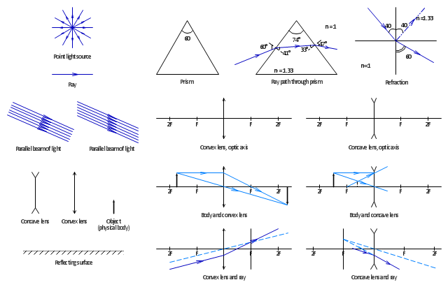
The vector stencils library "Optics" contains 17 symbol icons: reflecting surface; convex and concave lens with and without optic axis, body or ray; ray; parallel beam of light; point light source; prism with and without ray path; refraction.
Use these shapes for drawing schemes of physical experiments in geometrical optics and ray tracing diagrams.
"Geometrical optics, or ray optics, describes light propagation in terms of "rays". The "ray" in geometric optics is an abstraction, or "instrument", which can be used to approximately model how light will propagate. Light rays are defined to propagate in a rectilinear path as they travel in a homogeneous medium. Rays bend (and may split in two) at the interface between two dissimilar media, may curve in a medium where the refractive index changes, and may be absorbed and reflected. Geometrical optics provides rules, which may depend on the color (wavelength) of the ray, for propagating these rays through an optical system. This is a significant simplification of optics that fails to account for optical effects such as diffraction and interference. It is an excellent approximation, however, when the wavelength is very small compared with the size of structures with which the light interacts. Geometric optics can be used to describe the geometrical aspects of imaging, including optical aberrations." [Geometrical optics. Wikipedia]
The example "Design elements - Optics" was created using the ConceptDraw PRO diagramming and vector drawing software extended with the Physics solution from the Science and Education area of ConceptDraw Solution Park.
The vector stencils library "Local vehicular networking" contains 88 symbols for drawing the vehicular computer telecommunication network diagrams using the ConceptDraw PRO diagramming and vector drawing software.
"A vehicular ad hoc network (VANET) uses cars as mobile nodes in a MANET to create a mobile network.[1] A VANET turns every participating car into a wireless router or node, allowing cars approximately 100 to 300 metres of each other to connect and, in turn, create a network with a wide range. As cars fall out of the signal range and drop out of the network, other cars can join in, connecting vehicles to one another so that a mobile Internet is created. It is estimated that the first systems that will integrate this technology are police and fire vehicles to communicate with each other for safety purposes. ...
Vehicular ad hocal networks are expected to implement wireless technologies such as dedicated short-range communications (DSRC) which is a type of Wi-Fi. Other candidate wireless technologies are cellular, satellite, and WiMAX. Vehicular ad hoc networks can be viewed as component of the intelligent transportation systems (ITS).
As promoted in ITS, vehicles communicate with each other via inter-vehicle communication (IVC) as well as with roadside base stations via roadside-to-vehicle communication (RVC)." [Vehicular ad hoc network. Wikipedia]
The example "Design elements - Local vehicular networking" is included in the Vehicular Networking solution from the Computer and Networks area of ConceptDraw Solution Park.
"A vehicular ad hoc network (VANET) uses cars as mobile nodes in a MANET to create a mobile network.[1] A VANET turns every participating car into a wireless router or node, allowing cars approximately 100 to 300 metres of each other to connect and, in turn, create a network with a wide range. As cars fall out of the signal range and drop out of the network, other cars can join in, connecting vehicles to one another so that a mobile Internet is created. It is estimated that the first systems that will integrate this technology are police and fire vehicles to communicate with each other for safety purposes. ...
Vehicular ad hocal networks are expected to implement wireless technologies such as dedicated short-range communications (DSRC) which is a type of Wi-Fi. Other candidate wireless technologies are cellular, satellite, and WiMAX. Vehicular ad hoc networks can be viewed as component of the intelligent transportation systems (ITS).
As promoted in ITS, vehicles communicate with each other via inter-vehicle communication (IVC) as well as with roadside base stations via roadside-to-vehicle communication (RVC)." [Vehicular ad hoc network. Wikipedia]
The example "Design elements - Local vehicular networking" is included in the Vehicular Networking solution from the Computer and Networks area of ConceptDraw Solution Park.
The vector stencils library "Transmission paths" contains 43 symbols of power transmission paths, electronic circuits, bus connectors and elbows, terminals, junctions, and concentrators.
Use it to annotate electrical diagrams, electronic schematics and circuit diagrams.
"A physical medium in data communications is the transmission path over which a signal propagates.
Many transmission media are used as communications channel.
For telecommunications purposes in the United States, Federal Standard 1037C, transmission media are classified as one of the following:
(1) Guided (or bounded) - waves are guided along a solid medium such as a transmission line.
(2) Wireless (or unguided) - transmission and reception are achieved by means of an antenna.
One of the most common physical medias used in networking is copper wire. Copper wire to carry signals to long distances using relatively low amounts of power. The unshielded twisted pair (UTP) is eight strands of copper wire, organized into four pairs.
Another example of a physical medium is optical fiber, which has emerged as the most commonly used transmission medium for long-distance communications. Optical fiber is a thin strand of glass that guides light along its length.
Multimode and single mode are two types of commonly used optical fiber. Multimode fiber uses LEDs as the light source and can carry signals over shorter distances, about 2 kilometers. Single mode can carry signals over distances of tens of miles.
Wireless media may carry surface waves or skywaves, either longitudinally or transversely, and are so classified.
In both communications, communication is in the form of electromagnetic waves. With guided transmission media, the waves are guided along a physical path; examples of guided media include phone lines, twisted pair cables, coaxial cables, and optical fibers. Unguided transmission media are methods that allow the transmission of data without the use of physical means to define the path it takes. Examples of this include microwave, radio or infrared. Unguided media provide a means for transmitting electromagnetic waves but do not guide them; examples are propagation through air, vacuum and seawater.
The term direct link is used to refer to the transmission path between two devices in which signals propagate directly from transmitters to receivers with no intermediate devices, other than amplifiers or repeaters used to increase signal strength. This term can apply to both guided and unguided media.
A transmission may be simplex, half-duplex, or full-duplex.
In simplex transmission, signals are transmitted in only one direction; one station is a transmitter and the other is the receiver. In the half-duplex operation, both stations may transmit, but only one at a time. In full duplex operation, both stations may transmit simultaneously. In the latter case, the medium is carrying signals in both directions at same time." [Transmission medium. Wikipedia]
The shapes example "Design elements - Transmission paths" was drawn using the ConceptDraw PRO diagramming and vector drawing software extended with the Electrical Engineering solution from the Engineering area of ConceptDraw Solution Park.
 Reflected Ceiling Plans
Reflected Ceiling Plans solution is effective tool for architects, designers, electricians, and other people which every day need convenient tool for representing their ceiling ideas. Use it to create without efforts professional Reflected Ceiling plans and Reflective Ceiling plans, showing the location of light fixtures, drywall or t-bar ceiling patterns, lighting panels, and HVAC grilles and diffusers that may be suspended from the ceiling.
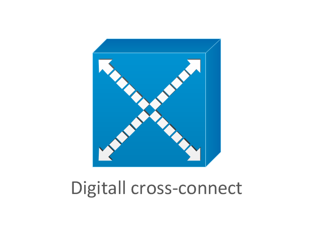
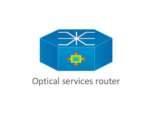
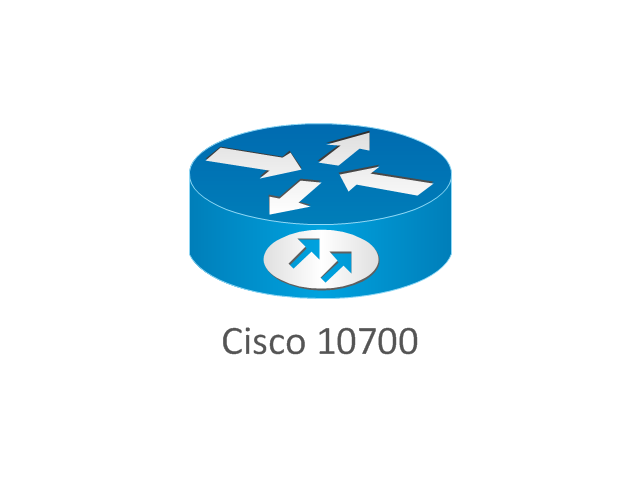
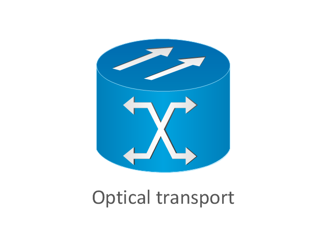
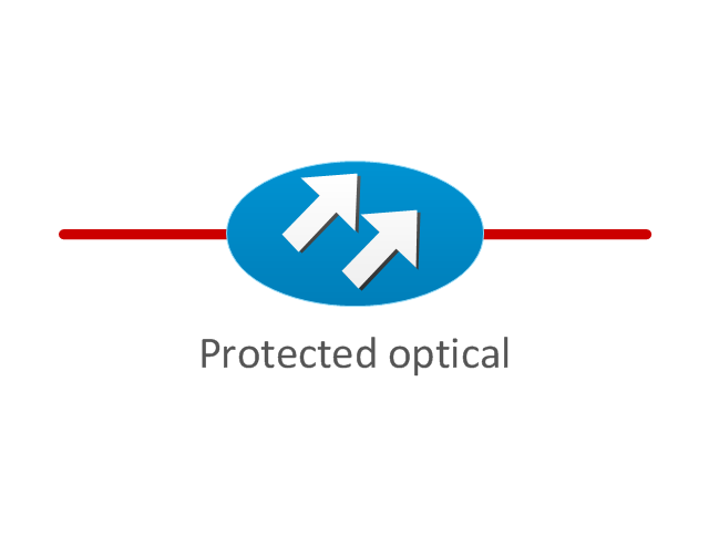
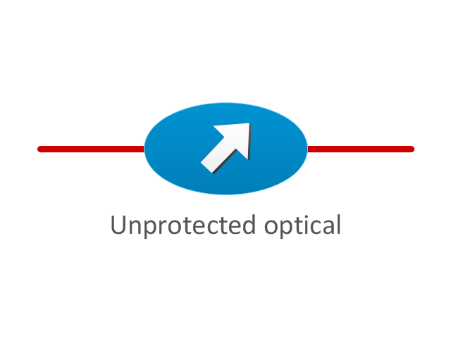
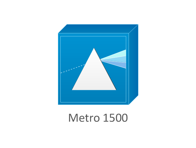
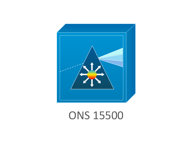
The vector stencils library "Cisco optical" contains 19 symbols of optical devices for drawing Cisco computer network diagrams.
"Fiber-optic communication is a method of transmitting information from one place to another by sending pulses of light through an optical fiber. The light forms an electromagnetic carrier wave that is modulated to carry information. ... Because of its advantages over electrical transmission, optical fibers have largely replaced copper wire communications in core networks in the developed world. Optical fiber is used by many telecommunications companies to transmit telephone signals, Internet communication, and cable television signals. ...
The process of communicating using fiber-optics involves the following basic steps: Creating the optical signal involving the use of a transmitter, relaying the signal along the fiber, ensuring that the signal does not become too distorted or weak, receiving the optical signal, and converting it into an electrical signal." [Fiber-optic communication. Wikipedia]
The symbols example "Cisco optical - Vector stencils library" was created using the ConceptDraw PRO diagramming and vector drawing software extended with the Cisco Network Diagrams solution from the Computer and Networks area of ConceptDraw Solution Park.
www.conceptdraw.com/ solution-park/ computer-networks-cisco
The design elements library "Cable TV" contains 64 symbols of CATV network equipment.
"Cable television is a system of distributing television programs to subscribers via radio frequency (RF) signals transmitted through coaxial cables or light pulses through fiber-optic cables. This contrasts with traditional broadcast television (terrestrial television) in which the television signal is transmitted over the air by radio waves and received by a television antenna attached to the television. FM radio programming, high-speed Internet, telephone service, and similar non-television services may also be provided through these cables.
The abbreviation CATV is often used for cable television." [Cable television. Wikipedia]
Use the shapes library "Cable TV" to draw CATV system design floor plans, network topology diagrams, wiring diagrams and cabling layout schemes using the ConceptDraw PRO diagramming and vector drawing software.
The vector stencils library "Cable TV" is included in the Electric and Telecom Plans solution from the Building Plans area of ConceptDraw Solution Park.
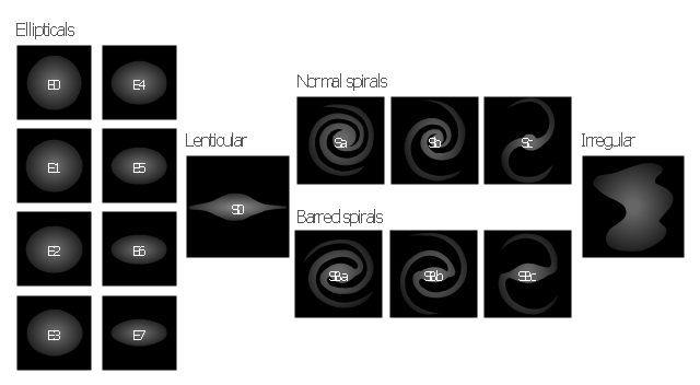
The vector stencils library "Galaxies" contains 15 galaxy symbols for drawing astronomical diagrams.
"A galaxy is a massive, gravitationally bound system consisting of stars, stellar remnants, an interstellar medium of gas and dust, and dark matter, an important but poorly understood component. The word galaxy is derived from the Greek galaxias ..., literally "milky", a reference to the Milky Way. Examples of galaxies range from dwarfs with as few as ten million (10^7) stars to giants with one hundred trillion (10^14) stars, each orbiting their galaxy's own center of mass.
Galaxies contain varying numbers of planets, star systems, star clusters and types of interstellar clouds. In between these objects is a sparse interstellar medium of gas, dust, and cosmic rays. Supermassive black holes reside at the center of most galaxies. They are thought to be the primary driver of active galactic nuclei found at the core of some galaxies. The Milky Way galaxy is known to harbor at least one such object.
Galaxies have been historically categorized according to their apparent shape, usually referred to as their visual morphology. A common form is the elliptical galaxy, which has an ellipse-shaped light profile. Spiral galaxies are disk-shaped with dusty, curving arms. Those with irregular or unusual shapes are known as irregular galaxies and typically originate from disruption by the gravitational pull of neighboring galaxies. Such interactions between nearby galaxies, which may ultimately result in a merger, sometimes induce significantly increased incidents of star formation leading to starburst galaxies. Smaller galaxies lacking a coherent structure are referred to as irregular galaxies."
[Galaxy. Wikipedia]
The example "Design elements - Galaxies" was created using the ConceptDraw PRO diagramming and vector drawing software extended with the Astronomy solution from the Science and Education area of ConceptDraw Solution Park.
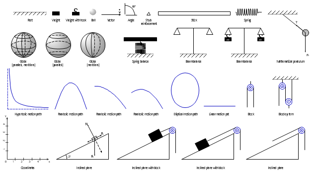
The vector stencils library "Mechanics" contains 29 symbol shapes for drawing mechanics experiment schemes and physical diagrams.
"Mechanics ... is the branch of science concerned with the behavior of physical bodies when subjected to forces or displacements, and the subsequent effects of the bodies on their environment. The scientific discipline has its origins in Ancient Greece with the writings of Aristotle and Archimedes. During the early modern period, scientists such as Galileo, Kepler, and especially Newton, laid the foundation for what is now known as classical mechanics. It is a branch of classical physics that deals with particles that are either at rest or are moving with velocities significantly less than the speed of light. It can also be defined as a branch of science which deals with the motion of and forces on objects." [Mechanics. Wikipedia]
The example "Design elements - Mechanics" was created using the ConceptDraw PRO diagramming and vector drawing software extended with the Physics solution from the Science and Education area of ConceptDraw Solution Park.
HelpDesk
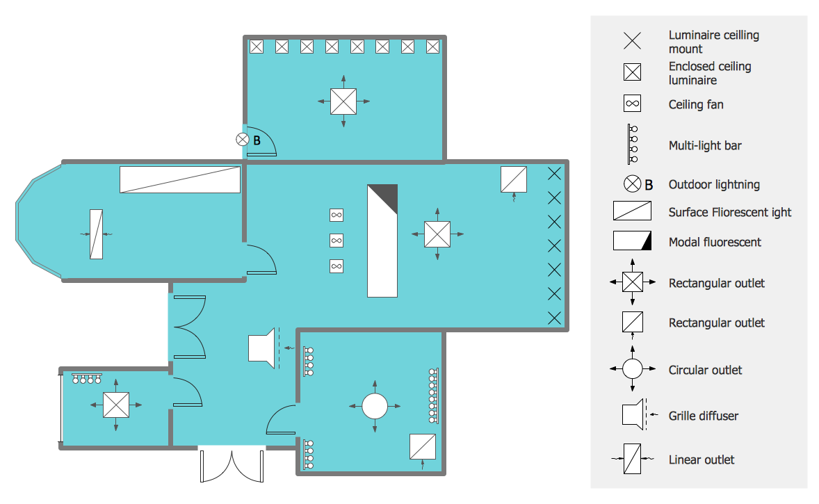
How to Create a Reflected Ceiling Floor Plan
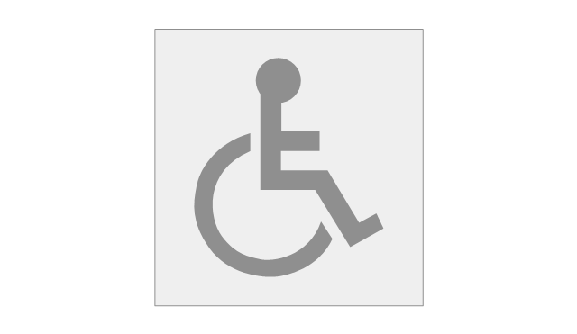
A Reflected Ceiling Plan (RCP) is a drawing of a room or building, looking down at the interior ceiling. Making RCP involves many different reflected ceiling plan symbols that can be managed using ConceptDraw PRO. Using ConceptDraw PRO you can design the reflected ceiling floor plan that shows the location of light fixtures and any other items that may be suspended from the ceiling. You can share your ceiling design ideas by saving drawings as graphics files, or printing them.The vector stencils library "Site accessories" contains 18 symbols of vehicle access control equipment (tollbooth, tollgate, parking fees payment box), a handicapped sign, outdoor lighting, and garbage receptacles. Use it to design site plans, parking lots drawings and site management diagrams the ConceptDraw PRO diagramming and vector drawing software extended with the Site Plans solution from the Building Plans area of ConceptDraw Solution Park.
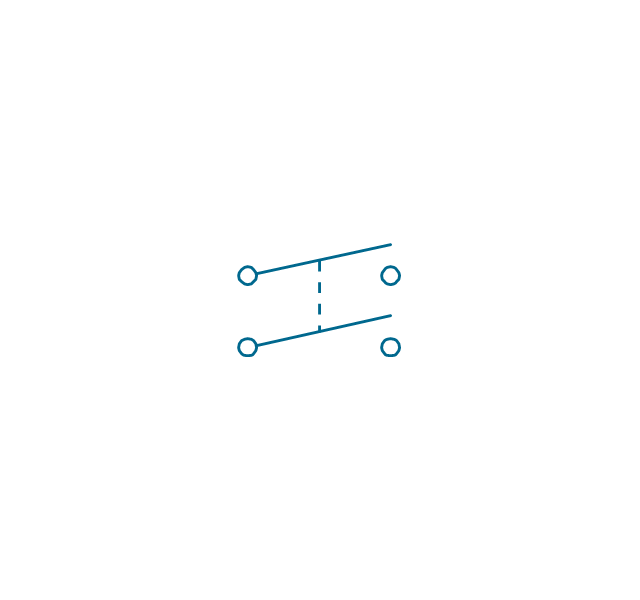
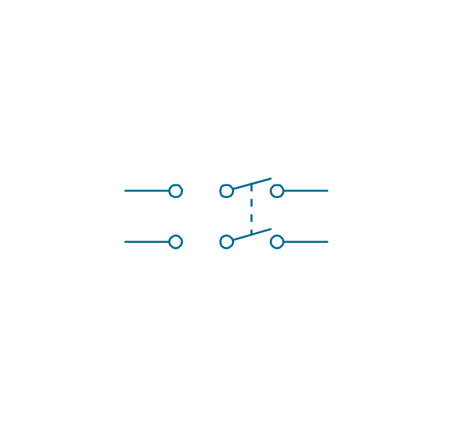
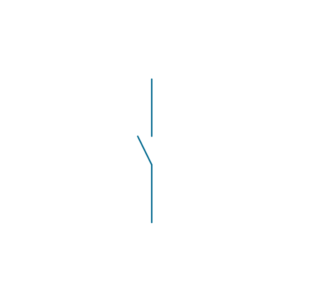
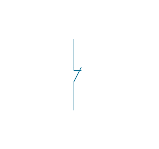
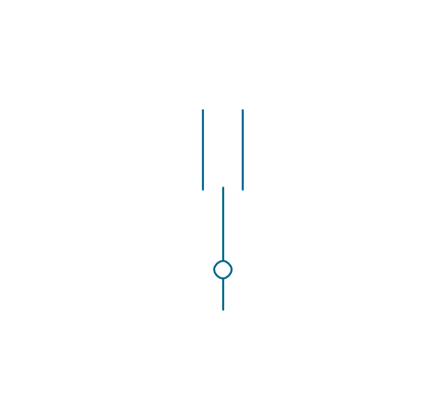
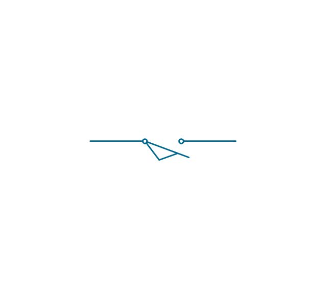
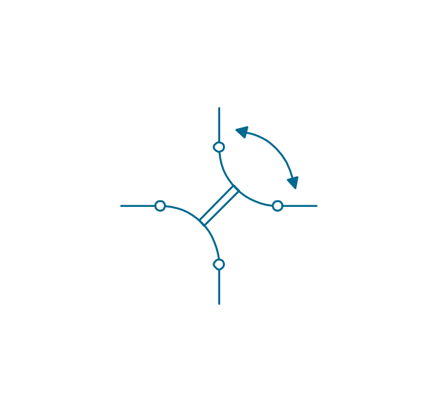
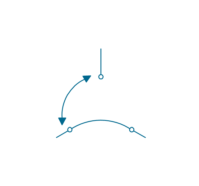
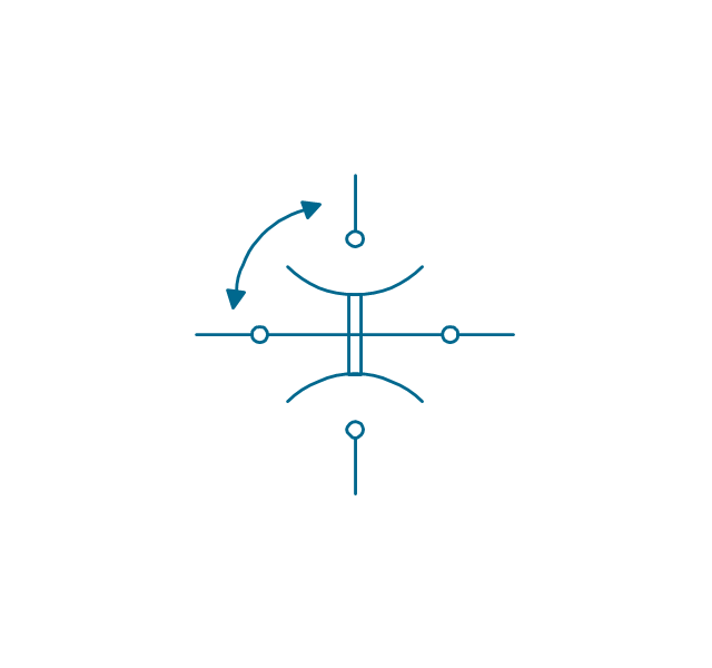
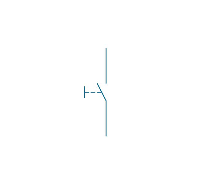
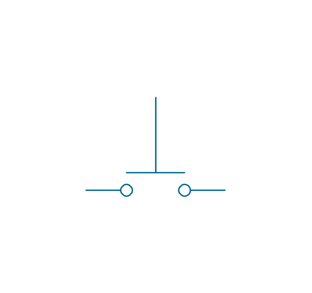
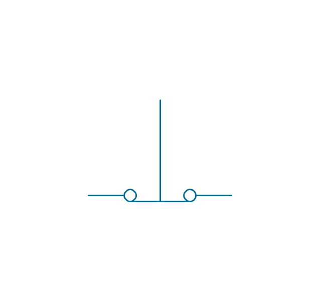
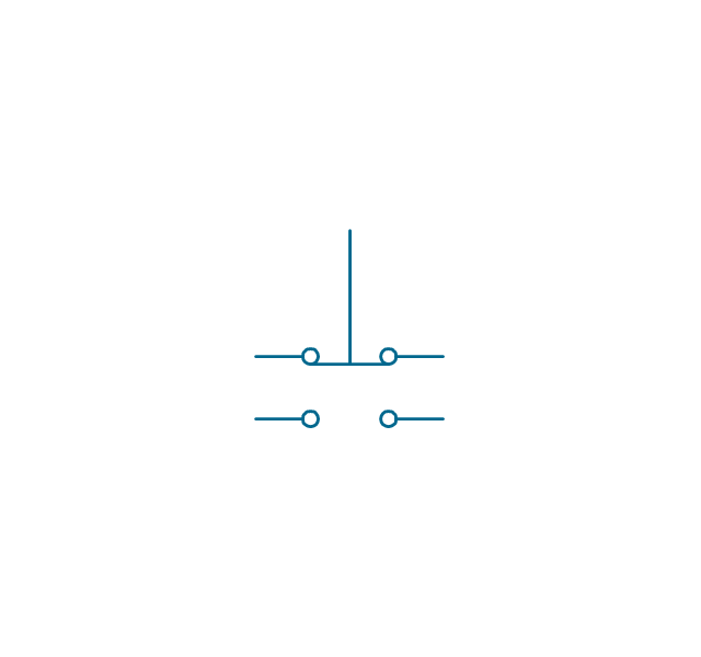
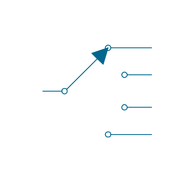
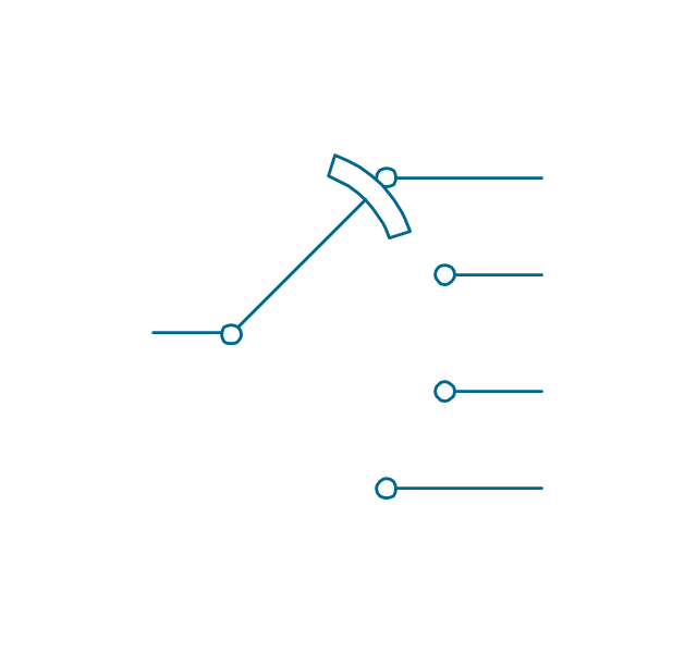
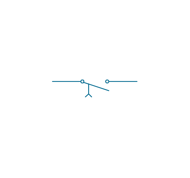
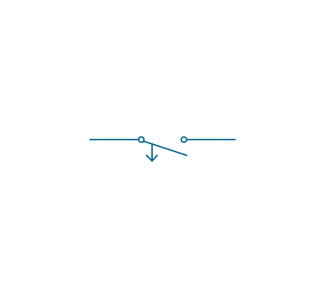
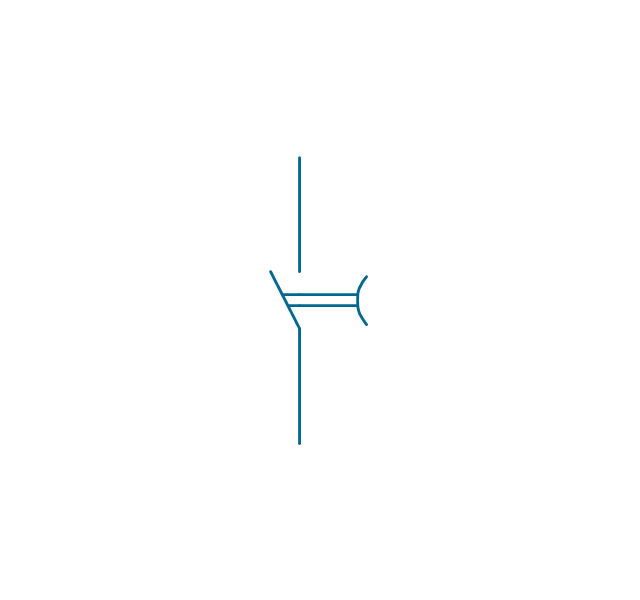
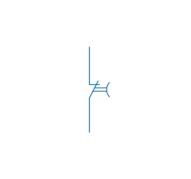
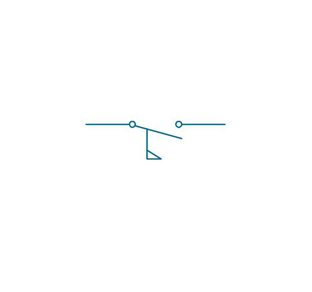
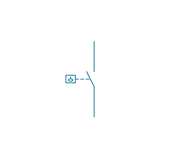
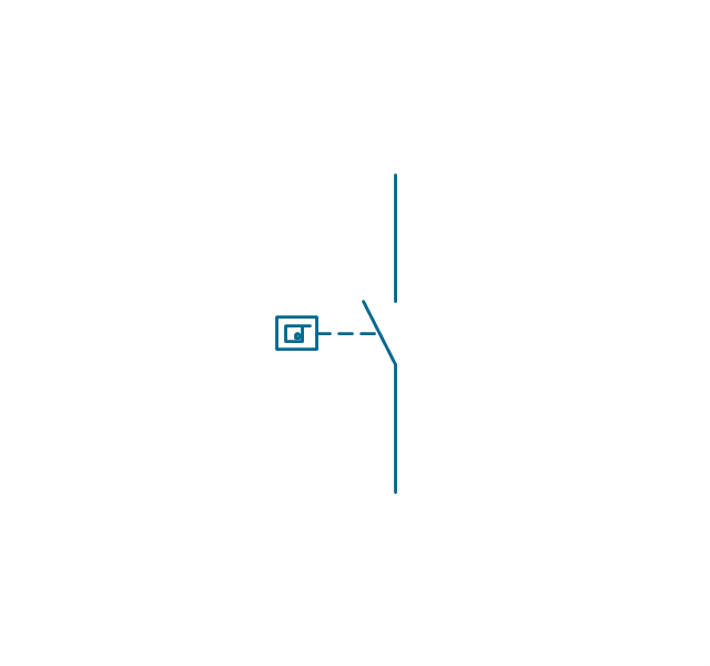
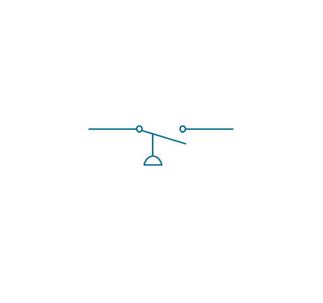
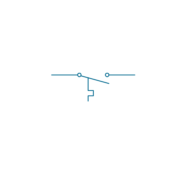
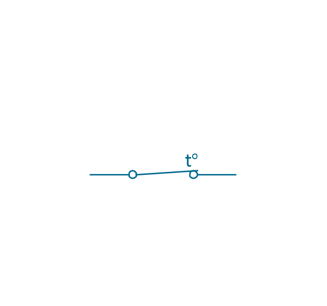
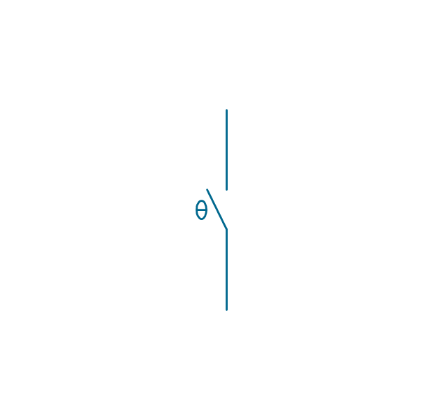
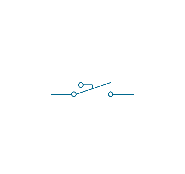
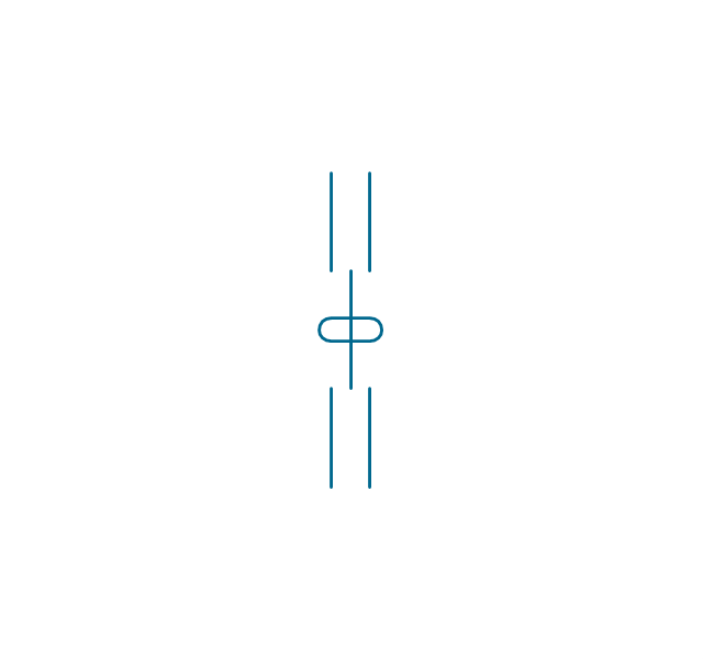
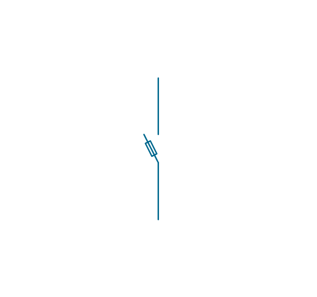
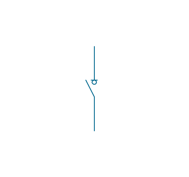
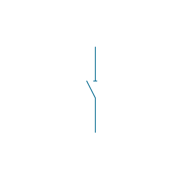
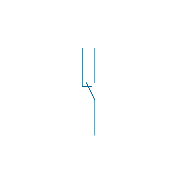
The vector stencils library "Switches and relays" contains 58 symbols of electrical contacts, switches, relays, circuit breakers, selectors, connectors, disconnect devices, switching circuits, current regulators, and thermostats for electrical devices.
Use these shapes for drawing electrical diagrams in the ConceptDraw PRO diagramming and vector drawing software extended with the Electrical Engineering solution from the Engineering area of ConceptDraw Solution Park.
www.conceptdraw.com/ solution-park/ engineering-electrical
Use these shapes for drawing electrical diagrams in the ConceptDraw PRO diagramming and vector drawing software extended with the Electrical Engineering solution from the Engineering area of ConceptDraw Solution Park.
www.conceptdraw.com/ solution-park/ engineering-electrical
- Electrical Drawing Software | How To use House Electrical Plan ...
- Lighting and switch layout | Design elements - Electrical and telecom
- Recessed Ceiling Lights Symbol In Diagram
- Design elements - Electrical and telecom | Building Drawing ...
- Design elements - Lighting | Design elements - Site accessories ...
- Electrical Lighting Symbols
- Design elements - Electrical and telecom | Design elements ...
- Design elements - Lighting | Classroom lighting - Reflected ceiling ...
- Design elements - Lighting | Design elements - Status indicators ...
- Lighting Plan Symbols Sockets
- Design elements - Switches | Network Glossary Definition | Electrical ...
- Design elements - Lighting | Interior Design Office Layout Plan ...
- Design elements - Lighting | Spotlight Symbol Floor Plan
- Electrical Diagram Symbols
- Design elements - Lighting | Lighting and switch layout | Interior ...
- How To use Appliances Symbols for Building Plan | How To use ...
- Interior Design Registers, Drills and Diffusers - Design Elements ...
- Lighting and switch layout | Design elements - Lighting | Design ...
- Electrical Drawing Software | Engineering | Electrical Engineering ...
- Reflected Ceiling Plans | Interior Design Registers, Drills and ...




-cisco-optical---vector-stencils-library.png--diagram-flowchart-example.png)

-cisco-optical---vector-stencils-library.png--diagram-flowchart-example.png)

.png--diagram-flowchart-example.png)
